Yamaha AX-590 Owner's Manual
Yamaha AX-590 Manual
 |
View all Yamaha AX-590 manuals
Add to My Manuals
Save this manual to your list of manuals |
Yamaha AX-590 manual content summary:
- Yamaha AX-590 | Owner's Manual - Page 1
, Sound Processor, etc. Remote Control Capability Thank you for selecting this YAMAHA stereo integrated amplifier. OWNER'S MANUAL CONTENTS Safety Instructions 2 Supplied Accessories 3 Connections 4 Operations 7 Remote Control Transmitter ... 11 Notes about the Remote Control - Yamaha AX-590 | Owner's Manual - Page 2
Servicing - The user should not attempt to service the unit beyond those means described in the operating instructions. All other servicing should be referred to qualified service personnel. 17 Power the AC power plug from the wall outlet. 10 Be sure to read the "TROUBLESHOOTING" section regarding - Yamaha AX-590 | Owner's Manual - Page 3
the instructions found in the users manual, may YAMAHA and the Electronic Industries Association's Consumer Electronics Group recommend you to avoid prolonged exposure from excessive volume levels. SUPPLIED ACCESSORIES After unpacking, check that the following parts are contained. q Remote Control - Yamaha AX-590 | Owner's Manual - Page 4
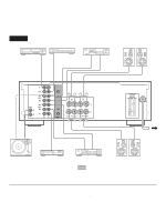
this unit, be sure to first switch OFF the power to this unit and to any other components to manual for each component to be connected to this unit. AX-590 Compact disc player Turntable Tape deck 2 Speakers A OUTPUT GND Right Left OUTPUT LINE OUT LINE IN PHONO GND MM/MC CD REMOTE CONTROL - Yamaha AX-590 | Owner's Manual - Page 5
1 SWITCHED OUTLET Use these to connect the power cords from your components to this unit. The power to the SWITCHED outlets is controlled by this unit's POWER switch or the provided remote control transmitter's POWER key. These outlets will supply power to any component whenever this unit is turned - Yamaha AX-590 | Owner's Manual - Page 6
/MAIN IN terminals AX-590 only Removing the jumper pins enables this unit to independently perform the functions of a control amplifier and a power amplifier. These terminals are for connection of a signalprocessing system such as a graphic equalizer or sound processor. If a sound processor or other - Yamaha AX-590 | Owner's Manual - Page 7
AX-590 OPERATIONS 2 7 1, 6 AX-490 47 3 2 7 1, 6 4 TO PLAY A SOURCE 1 VOLUME l8 l6 l4 20 l2 24 l0 28 8 34 6 40 4 50 3 60 2 70 l 0 -dB ∞ Set to the " " position. 2 Turn the power on. POWER 3 Select a desired input source. INPUT CD TAPE 1 TUNER TAPE 2 PHONO - Yamaha AX-590 | Owner's Manual - Page 8
AX-590 REC OUT TAPE 1 CD TUNER TEAP 2 PHONO AUX AX-490 REC OUT CD TAPE 1 TUNER TAPE 2 PHONO AUX 2 Play the source. 3 Confirm the source by selecting it with the INPUT selector and turning up the VOLUME control LOUDNESS controls, CD DIRECT AMP switch and PURE DIRECT switch settings have - Yamaha AX-590 | Owner's Manual - Page 9
Adjusting the BALANCE control Adjust the balance of the output volume to the left and right speakers to compensate for sound imbalance caused from speaker location or listening room conditions. AX-590 AX-490 BALANCE l 0l 2 2 3 3 4 L5 4 5R BALANCE 0 l l 2 2 3 3 4 L5 4 5R - Yamaha AX-590 | Owner's Manual - Page 10
controls, and then sent to the power amplifier. This signal routing reproduces the purest CD sound eliminating any alterations to the CD signals. AX-590 only * The SUBSONIC FILTER switch and the PRE OUT/MAIN IN terminals are also bypassed. CD DIRECT AMP Setting the SUBSONIC FILTER switch AX-590 - Yamaha AX-590 | Owner's Manual - Page 11
tape deck connected to this unit are YAMAHA components designed for remote control compatibility, then this remote control transmitter will also control various functions of each component. KEY FUNCTIONS For Control of This Unit Turns the power on/off. POWER SKIP PLAY/CUT PHONO PLAY CD SEARCH - Yamaha AX-590 | Owner's Manual - Page 12
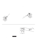
long period of time. POWER POWER on mode POWER STANDBY mode NOTES ABOUT THE REMOTE CONTROL TRANSMITTER Battery installation Remote control transmitter operation range 2 1 3 AX-590 AX-490 Remote control sensor Battery replacement If you find that the remote control transmitter must be used - Yamaha AX-590 | Owner's Manual - Page 13
. Using the BASS, TREBLE, BALANCE, LOUDNESS controls and SUBSONIC FILTER switch (AX-590 only) does not affect the tone. The remote control transmitter does not work. The distance or range within which the remote control transmitter can be used decreases. CAUSE Power cord is not plugged in or is not - Yamaha AX-590 | Owner's Manual - Page 14
Dimensions (W x H x D) - Yamaha AX-590 | Owner's Manual - Page 15
ELECTRONIQUE FRANCE S.A. RUE AMBROISE CROIZAT BP70 CROISSY-BEAUBOURG 77312 MARNE-LA-VALLEE CEDEX02, FRANCE YAMAHA ELECTRONICS (UK) LTD. YAMAHA HOUSE, 200 RICKMANSWORTH ROAD WATFORD, HERTS WD1 7JS, ENGLAND YAMAHA SCANDINAVIA A.B. J A WETTERGRENS GATA 1, BOX 30053, 400 43 VÄSTRA FRÖLUNDA, SWEDEN
-
 1
1 -
 2
2 -
 3
3 -
 4
4 -
 5
5 -
 6
6 -
 7
7 -
8
-
9
-
10
-
11
-
12
-
13
-
14
-
15
 |
 |
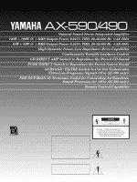
Natural Sound Stereo Integrated Amplifier
100W + 100W (8
Ω
) RMS Output Power, 0.015% THD, 20–20,000 Hz
<
AX-590
>
85W + 85W (8
Ω
) RMS Output Power, 0.019% THD, 20–20,000 Hz
<
AX-490
>
High Dynamic Power, Low Impedance Drive Capability
Continuously Variable Loudness Control
CD DIRECT AMP Switch to Reproduce the Purest CD Sound
PURE DIRECT Switch to Reproduce the Purest Source Sound
SUBSONIC FILTER Switch to Cut Out Undesirable
Ultra-Low-Frequency Signals
<
For AX-590 only
>
PRE OUT/MAIN IN Terminals Useful for Connecting An Equalizer,
Sound Processor, etc.
<
For AX-590 only
>
Remote Control Capability
Thank you for selecting this YAMAHA stereo integrated amplifier.
CONTENTS
Safety Instructions
...................
2
Supplied Accessories
..............
3
Connections
.............................
4
Operations
...............................
7
Remote Control Transmitter ... 11
Notes about the Remote
Control Transmitter
.................
12
Troubleshooting
......................
13
Specifications
.........................
14
AX-590/490
IMPORTANT!
Please record the serial number of this
unit in the space below.
Serial No.:
The serial number is located on the rear
of the unit.
Retain this Owner’s Manual in a safe
place for future reference.
WARNING
TO REDUCE THE RISK OF FIRE OR
ELECTRIC SHOCK, DO NOT EXPOSE
THIS UNIT TO RAIN OR MOISTURE.
RISK OF ELECTRIC
SHOCK
CAUTION:
TO REDUCE THE RISK OF
ELECTRIC SHOCK, DO NOT REMOVE
COVER (OR BACK), NO USER-SERVICEABLE
PARTS INSIDE, REFER SERVICING TO
QUALIFIED SERVICE PERSONNEL.
The lightning flash with arrowhead
symbol, within an equilateral triangle,
is intended to alert you to the
presence of uninsulated “dangerous
voltage” within the product’s
enclosure that may be of sufficient
magnitude to constitute a risk of
electric shock to persons.
The exclamation point within an
equilateral triangle is intended to alert
you to the presence of important
operating and maintenance
(servicing)
instructions in the
literature accompanying the
appliance.
•
Explanation of Graphical Symbols
CAUTION
OWNER’S MANUAL