Yamaha DSP-A2 Owner's Manual - Page 22
Connecting an external decoder of a future format to this unit, SUBWOOFER, SURROUND OUT, CENTER
 |
View all Yamaha DSP-A2 manuals
Add to My Manuals
Save this manual to your list of manuals |
Page 22 highlights
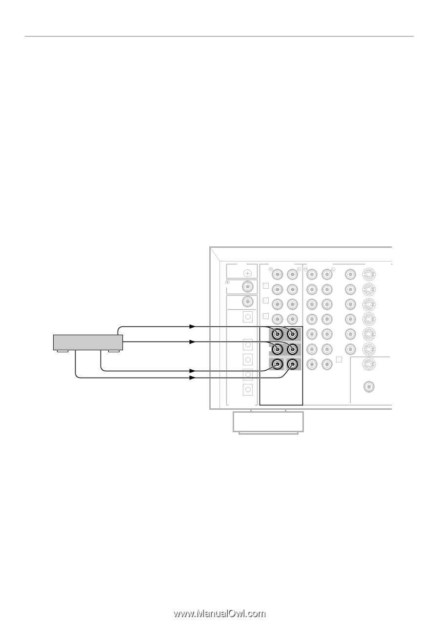
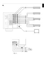
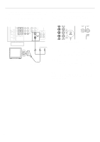
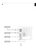
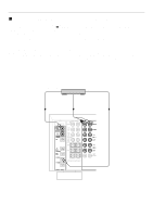
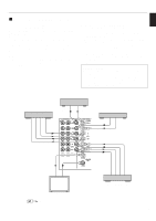
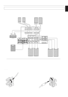
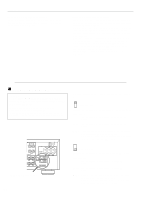
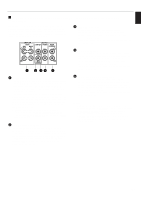
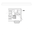
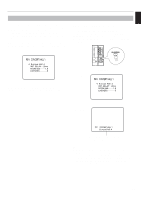
PREPARATION Ⅵ Connecting an external decoder of a future format to this unit This unit is equipped with additional 6-channel audio signal input terminals (for left main, right main, center, left rear surround, right rear surround and subwoofer channels) for inputting signals from an external decoder of a future format to this unit. To listen to a sound by reproducing signals input to these terminals, press the EXT. DECODER button on the front panel so that "EXT. DECODER IN" appears on the display. By doing so, the signals input to these terminals are sent to the corresponding SPEAKERS terminals and OUTPUT terminals of this unit. Notes q When signals input to these terminals are selected, the digital sound field processor cannot be used. q The settings of "1A" to "1E" in the SET MENU mode have no effect on the signals input to these terminals. The setting of "1F. MAIN LEVEL" is effective. (Refer to pages 26 to 27 for details.) q The adjustments of the output level of the center speaker, rear speakers and subwoofer are effective when the signals input to these terminals are selected as the input source. (Refer to pages 43 to 44 for details.) External decoder MAIN OUT SURROUND OUT CENTER OUT SUBWOOFER OUT (Europe model) GND DIGITAL RF SIGNAL DVD/LD CD COAXIAL OPTICAL CD IN (PLAY) TAPE/MD OUT (REC) DVD/LD TV/DBS AUDIO SIGNAL PHONO AUDIO SIGNAL VIDEO DVD/LD VIDEO SIGNAL S VIDEO DVD/LD 1 CD 3 IN ( PLAY ) TAPE/MD 4 OUT ( REC ) MAIN SURROUND SUB WOOFER CENTER EXTERNAL DECODER INPUT TV/DBS IN VCR 1 OUT IN VCR 2 OUT 2 TUNER TV/DBS IN VCR 1 OUT IN VCR 2 OUT S VIDEO MONITOR OUT VIDEO DIGITAL SIGNAL 20
-
 1
1 -
2
-
3
-
4
-
5
-
6
-
7
-
8
-
9
-
10
-
11
-
12
-
13
-
14
-
15
-
16
-
 17
17 -
 18
18 -
 19
19 -
 20
20 -
 21
21 -
 22
22 -
 23
23 -
 24
24 -
 25
25 -
 26
26 -
 27
27 -
28
-
29
-
30
-
31
-
32
-
33
-
34
-
35
-
36
-
37
-
38
-
39
-
40
-
41
-
42
-
43
-
44
-
45
-
46
-
47
-
48
-
49
-
50
-
51
-
52
-
53
-
54
-
55
-
56
-
57
-
58
-
59
-
60
-
61
-
62
-
63
-
64
-
65
-
66
-
67
-
68
-
69
-
70
-
71
-
72
-
73
-
74
-
75
-
76
-
77
-
78
 |
 |