Yamaha EMX5000-20 Owner's Manual - Page 16
Graphic equalizer Power amp ST L-R, AUX 1-MONO, AUX 1-AUX 2, MONO BRIDGE
 |
View all Yamaha EMX5000-20 manuals
Add to My Manuals
Save this manual to your list of manuals |
Page 16 highlights
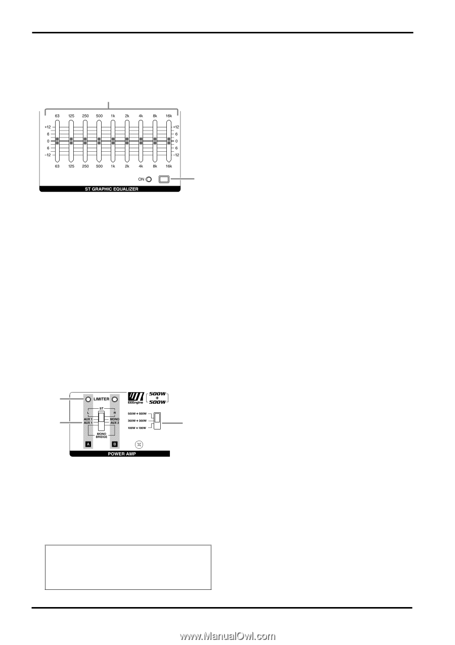
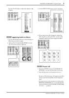
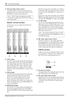
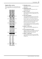
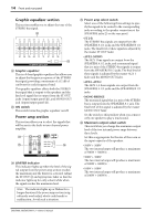
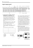
14 Front and rear panel s Graphic equalizer section This section enables you to adjust the tone of the STEREO bus signal. V W V Graphic equalizer This is a 9-band graphic equalizer that allows you to adjust the frequency response of the STEREO bus signal, providing a maximum of ±12 dB of cut/boost for each frequency band. This graphic equalizer affects both the STEREO bus signal that is output to the speakers and the line level signal that is output from the ST OUT jacks (input/output panel 0), and MONO OUT jack (input/output panel C). W ON switch This switch turns the graphic equalizer on/off. s Power amp section This section allows you to select the signals that will be sent to the built-in two-channel power amplifier. X Y Z X LIMITER indicator This indicator lights up when the level of the signal output from the power amp section reaches the maximum and the limiter is activated. Adjust the ST OUT K and appropriate fader so that the indicator lights up for only a short while when the signal reaches the maximum level. Note: The indicator lights up or flashes for a longer duration if the power amp section is significantly overloaded, which could result in malfunction. Avoid such a situation. Y Power amp select switch Select one of the following three settings to specify the signals to be routed to the corresponding jacks according to the speaker connection at the SPEAKERS jacks 3 on the rear panel. • ST L-R The STEREO bus signals are output from the SPEAKERS A 1/2 jacks and the SPEAKERS B 1/2 jacks. The final level of these signals is adjusted by the master ST OUT fader. • AUX 1-MONO The AUX 1 bus signals are output from the SPEAKERS A 1/2 jacks, and a monaural signal that is a mix of the STEREO bus signals is output from the SPEAKERS B 1/2 jacks. The final level of these signals is adjusted by the master AUX 1 fader and the MONO OUT fader. • AUX 1-AUX 2 The AUX 1, 2 buses signals are output from the SPEAKERS A 1/2 jacks and the SPEAKERS B 1/2 jacks. • MONO BRIDGE The monaural signal that is a mix of the STEREO bus is output from the SPEAKERS A 1 jack. The final level of this signal is adjusted by the master MONO OUT fader. Set the switch to this position when you connect only one speaker to play a loud sound. Z Maximum output select switch This switch lets you change the maximum output level of the two internal power amps between three levels. Set this as appropriate for the size of the room or the input capacity of the speakers. • 500W + 500W The two internal amps will produce a maximum of 500W + 500W/4Ω. • 300W + 300W The two internal amps will produce a maximum of 300W + 300W/4Ω. • 100W + 100W The two internal amps will produce a maximum of 100W + 100W/4Ω. EMX5000-20/EMX5000-12-Owner's Manual
-
 1
1 -
2
-
3
-
4
-
5
-
6
-
7
-
8
-
9
-
10
-
 11
11 -
 12
12 -
 13
13 -
 14
14 -
 15
15 -
 16
16 -
 17
17 -
 18
18 -
 19
19 -
 20
20 -
 21
21 -
22
-
23
-
24
-
25
-
26
-
27
-
28
-
29
-
30
-
31
-
32
-
33
-
34
-
35
-
36
-
37
-
38
 |
 |