Yamaha EMX5000-20 Owner's Manual - Page 19
P.AMP IN A, B power amp input jacks, EFFECT SEND 1 jack - powered mixer
 |
View all Yamaha EMX5000-20 manuals
Add to My Manuals
Save this manual to your list of manuals |
Page 19 highlights
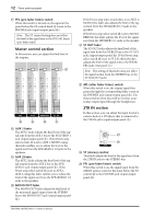
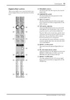
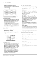
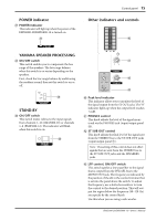
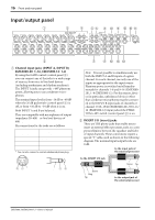
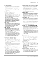
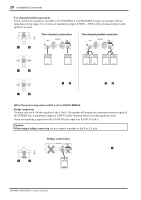
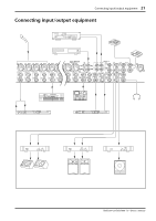
Input/output panel 17 3 PHANTOM switch This is an on/off switch for the phantom power supplied to the INPUT A jacks of channels 1-8 and 9-16 (on the EMX5000-20) or channels 1-8 (on the EMX5000-12). When this switch is on, the indicator in the upper part of the control panel will light. 4 LINE (stereo) input jacks EMX5000-20: 17/18-19/20, EMX5000-12: 9/10-11/12 These are the input jacks for channels 17/18-19/ 20, 9/10-11/12 and are used to connect to the stereo output jacks of electronic instruments, cassette decks, or CD players. You can connect either phone plugs or RCA phono plugs, as appropriate for the type of jack on the device you are connecting. The nominal input level is from -34 dB to +10 dB. 5 2TR IN jacks These are phono jacks that allow the signal from an external device, such as a cassette deck and CD player, to be added to the STEREO bus. The nominal input level is -10 dBV. 6 REC OUT jacks These phono jacks are used to connect to the inputs of a recording device, such as a cassette deck, to record the signal from the STEREO bus. The nominal output level is -10 dBV. Note: The setting of the graphic equalizer or ST OUT fader on the control panel does not affect the signals output from these jacks. Adjust the recording level on the recording device. 7 ST SUB IN 1 (stereo sub 1) jacks ST SUB IN 2 (stereo sub 2) jacks These phone jacks are used to connect stereo outputs of a sub mixer or external effect processor. The signal input here can be routed to the AUX 1 bus, AUX 2 bus, and STEREO bus. The nominal input level is +4 dB. Note: Use only the L jack to connect a monaural output device. 8 AUX SEND 1 jack, AUX SEND 2 jack These phone jacks output the line-level signals of the AUX 1/2 buses. Connect stage-monitoring amplifiers or powered speakers here. Use the AUX 1 fader (control panel H) and the AUX 2 fader (control panel I) respectively to adjust the final level of the signals output from these jacks. The nominal output level is +4 dB. 9 EFFECT SEND 1 jack, EFFECT SEND 2 jack The input of an external effect unit such as a delay or echo can be connected to this jack. The signal adjusted by the EFF 1, 2 control of each channel will be sent to the EFFECT 1, 2 bus, and output from this jack. The nominal output level is +4 dB. 0 ST OUT jacks These phone jacks output the line level signal of the STEREO bus. The final output level from these jacks is adjusted by the ST OUT fader (control panel K). The nominal output level is +4 dB. A ST SUB OUT jacks These phone jacks output the line-level signals of the STEREO bus. Connect an external mixer or additional PA system to these jacks. Use the ST SUB OUT control (control panel b) to adjust the final output level at the ST SUB OUT jacks. The nominal output level is +4 dB. B P.AMP IN A, B (power amp input) jacks These phone jacks are used to input line-level stereo signals to the two-channel built-in power amplifier. Connect an external mixer output here. The nominal input level is +4 dB. Note: If you insert a plug into this jack, the corresponding channel of the power amplifier will be isolated, and no signals will be sent from the mixer section. C MONO OUT jack This phone jack mixes the STEREO bus signals and output a monaural signal. Connect an additional PA system here. Use the MONO OUT fader (control panel J) to adjust the final level of the signal output from this jack. The nominal output level is +4 dB. D PHONES jack This is a stereo phone type output jack, and is used to monitor the channels selected by the PFL switches on the front panel and the buses selected by the AFL switches. The nominal output is 3mW when headphones are connected. E FOOT SW EFFECT 2 ON/OFF jack A separately sold Yamaha FC5 foot switch can be connected to this jack so you can use your foot to switch the built-in digital EFFECT 2 on/off. EMX5000-20/EMX5000-12-Owner's Manual
-
 1
1 -
2
-
3
-
4
-
5
-
6
-
7
-
8
-
9
-
10
-
11
-
12
-
13
-
 14
14 -
 15
15 -
 16
16 -
 17
17 -
 18
18 -
 19
19 -
 20
20 -
 21
21 -
 22
22 -
 23
23 -
 24
24 -
25
-
26
-
27
-
28
-
29
-
30
-
31
-
32
-
33
-
34
-
35
-
36
-
37
-
38
 |
 |