Yamaha EMX5000-20 Owner's Manual - Page 2
The Owner's Manual Revisions, POWER amp Other indicators and controls, Rear panel - 12
 |
View all Yamaha EMX5000-20 manuals
Add to My Manuals
Save this manual to your list of manuals |
Page 2 highlights
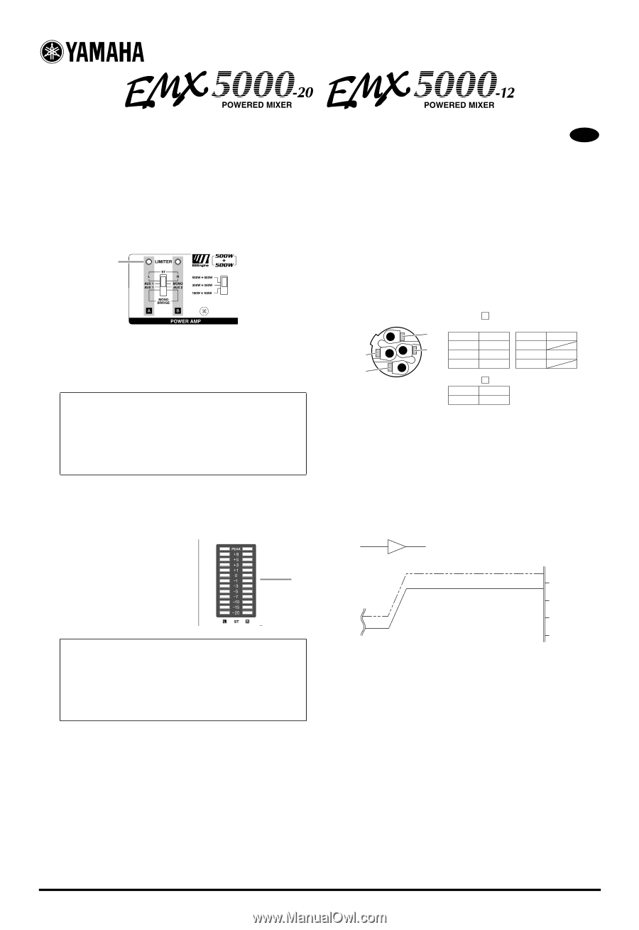
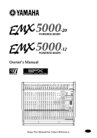
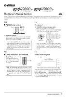
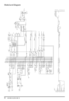
The Owner's Manual Revisions E Thank you for purchasing the Yamaha EMX5000-20/EMX5000-12 Powered Mixer. Parts of the EMX5000-20, EMX5000-12 owner's manual have been revised. Please refer to the following revisions rather than the corresponding sections of the original owner's manual. P.14 ■ POWER amp section X X LIMITER indicator If the output level of signals received at the SPEAKERS jacks (output of the internal power amplifier) reaches maximum, the indicator will light. Caution: If the LIMITER indicator flashes continuously, the internal power amplifier section is being excessively overloaded and may malfunction. Reduce the output level at the ST OUT fader (K) below the level that the indicator flashes only briefly on the highest transient peaks. P.18 Rear panel 3 SPEAKERS (speaker output) jacks These jacks are used to connect speakers. Jacks 1 are Speakon-type connectors. Use only Neutrik NL4FC plugs for connecting Speakon connectors. CHANNEL A STEREO/PARALLEL 2- 1+ A+ 2+ 1- A- 1+ 2+ B+ 2- B- 1- Neutrik NL4FC CHANNEL B 1+ B+ 1- B- BRIDGE 1+ + 1- 2+ - 2- Jacks 2 are 1/4"phone jacks. The setting of the control panel power amp select switch Y will determine the signal that is output to these jacks, and the number and appropriate impedance of the speakers that can be connected. P.15 ■ Other indicators and controls ^ Level Meter This LED display shows the level of signals received at the ` ST OUT jack (input/output panel 0). Note: The SPEAKERS 1 & 2 jacks (rear panel 3) output the signals received at the ST OUT jack via the internal power amplifier. Check the output signal level via the LIMITER indicator (X). The LIMITER indicator will light before the Level Meter "8" or "PEAK" LED light. P.33 Block/Level Diagram PA SPEAKERS OUT MAXIMUM OUTPUT [500W/4Ω] NOMINAL OUTPUT [100W/4Ω] +30dB +11dB +4dB +20dB +10dB 0dB Power Amplifier output section level diagram (bottom right) These plots show the nominal output and maximum output levels of signals received at the SPEAKERS jacks. If the output level is +4dB (Level Meter "0"), the internal power amplifier will deliver 100W into a 4Ω load. If the output level is +11dB (LIMITER indicator lights), the internal amplifier will deliver a maximum of 500W into 4Ω. 1 EMX5000-20/EMX5000-12
-
 1
1 -
 2
2 -
 3
3 -
 4
4 -
 5
5 -
 6
6 -
 7
7 -
 8
8 -
9
-
10
-
11
-
12
-
13
-
14
-
15
-
16
-
17
-
18
-
19
-
20
-
21
-
22
-
23
-
24
-
25
-
26
-
27
-
28
-
29
-
30
-
31
-
32
-
33
-
34
-
35
-
36
-
37
-
38
 |
 |