Yamaha EMX5000-20 Owner's Manual - Page 20
Rear panel, FOOT SW EFFECT 2 TAP jack, LAMP jack, AC inlet, POWER switch
 |
View all Yamaha EMX5000-20 manuals
Add to My Manuals
Save this manual to your list of manuals |
Page 20 highlights
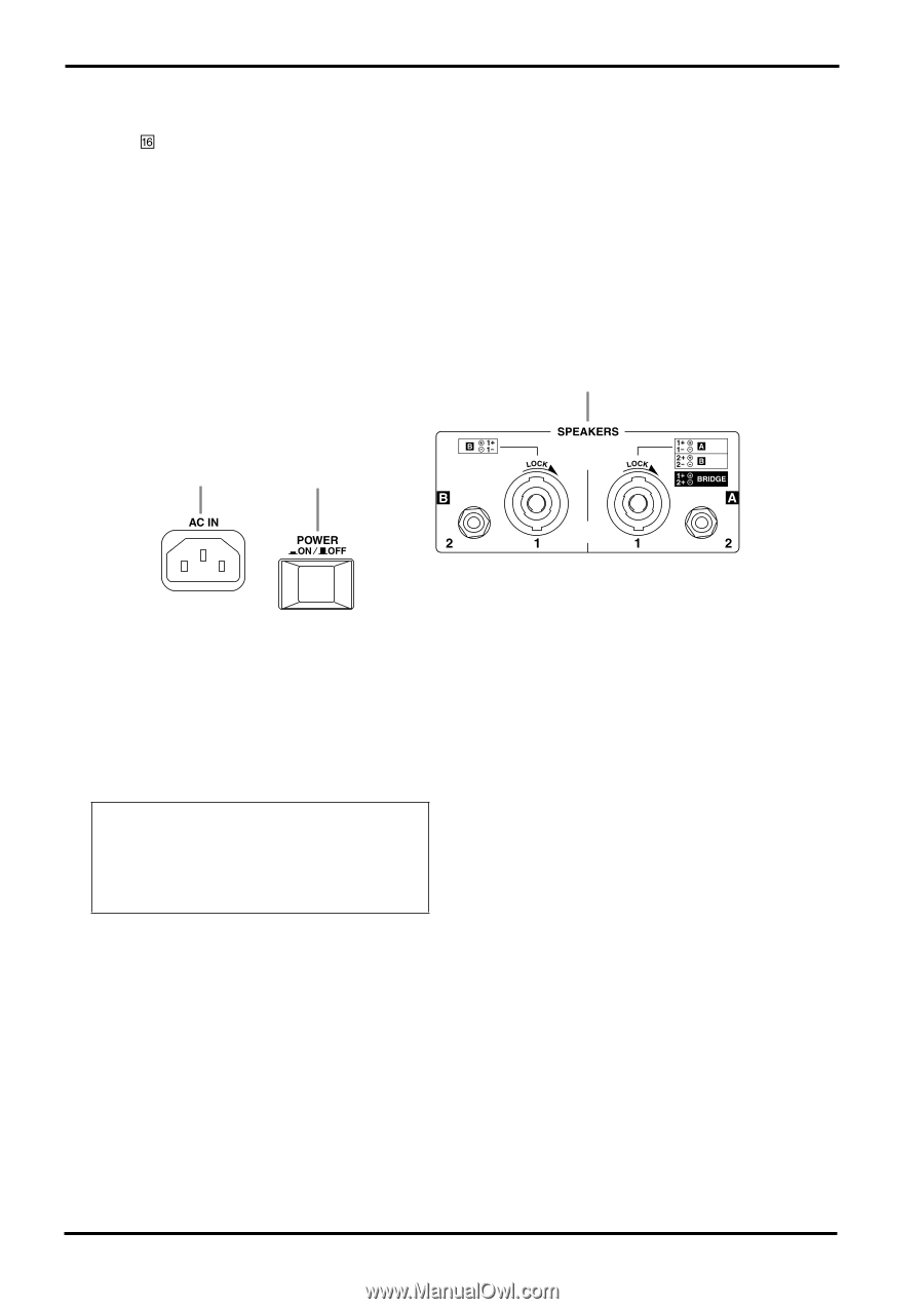
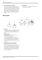
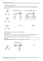
18 Front and rear panel F FOOT SW (EFFECT 2) TAP jack When TAP DELAY is selected as the internal effect type for the EFFECT 2 RTN channel, you can connect a separately sold FC5 foot switch to this jack, and press the foot switch to set the delay time to the corresponding interval. When you press the foot switch several times, the delay time will be set to the interval between the last two presses. Rear panel G LAMP jack This is an XLR (3-pin female) output jack that supplies power to a lamp. 3 1 2 1 AC inlet Connect the socket end of the included AC cable to this inlet. Connect the plug end of the cable to an AC outlet of the voltage printed below the inlet. 2 POWER switch This switch turns on/off the power to the EMX5000-20/EMX5000-12. Note: Before you turn the power of the EMX5000-20/EMX5000-12 on or off, the faders and controls in the master section of the control panel must be lowered to the minimum position. 3 SPEAKERS (speaker output) jacks These jacks are used to connect speakers. Jacks 1 are Speakon-type connectors. Jacks 2 are 1/4" phone jacks. The setting of the control panel power amp select switch Y will determine the signal that is output to these jacks, and the number and appropriate impedance of the speakers that can be connected. EMX5000-20/EMX5000-12-Owner's Manual
-
 1
1 -
2
-
3
-
4
-
5
-
6
-
7
-
8
-
9
-
10
-
11
-
12
-
13
-
14
-
 15
15 -
 16
16 -
 17
17 -
 18
18 -
 19
19 -
 20
20 -
 21
21 -
 22
22 -
 23
23 -
 24
24 -
 25
25 -
26
-
27
-
28
-
29
-
30
-
31
-
32
-
33
-
34
-
35
-
36
-
37
-
38
 |
 |