Yamaha EMX5000-20 Owner's Manual - Page 21
Installation/Connections, Installation, Connection, Connecting main speakers - ratings
 |
View all Yamaha EMX5000-20 manuals
Add to My Manuals
Save this manual to your list of manuals |
Page 21 highlights
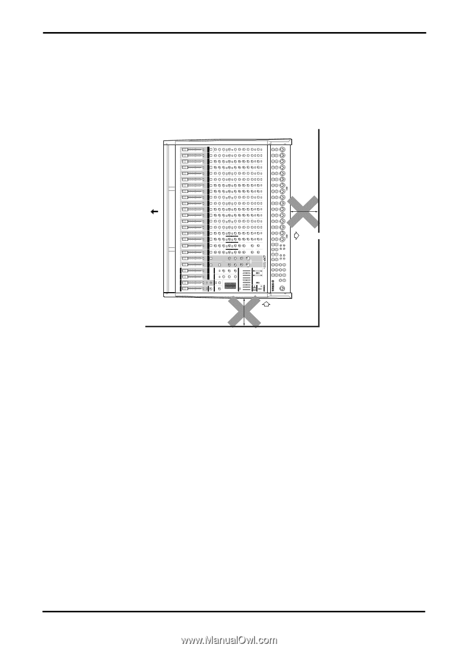
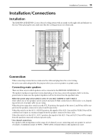
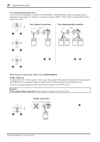
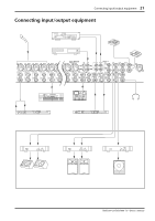
Installation/Connections 19 Installation/Connections Installation The EMX5000-20/EMX5000-12 uses a forced cooling system with air intake on the right side and exhaust on the rear. When placing the unit, make sure that the cooling ports are not obstructed. Front NO 30cm or less Exhaust NO 30cm Intake or less Connection When connecting various devices, make sure the cables and plugs have the correct rating. Be sure to use cables designed for the purpose when you connect speakers to speaker jacks. s Connecting main speakers There are three ways in which speakers can be connected to the EMX5000-20/EMX5000-12. The speaker impedance requirement varies depending on how you connect the speakers. Refer to the diagrams below to make sure the speaker impedance will not be lower than the specified value. s When the power amp select switch is set to ST L-R, AUX 1-MONO or AUX 1-AUX 2: Select either one or two speakers each to jacks A and jacks B. Make connections to either jacks 1 or 2, depending on the type of speaker cable you are using. When the power amp select switch is in the ST L-R position, the signals of the stereo L and R bus will be output from the speakers connected to jacks A and B respectively. When this switch is in the AUX 1-MONO position, the signals of the AUX 1 bus and the STEREO bus will be combined and output as a monaural signal from the speakers connected to these jacks. When this switch is in the AUX 1-AUX 2 position, the signals of the AUX 1 bus and AUX 2 bus will be output from the speakers connected to these respective jacks. • Two channel connections Use speakers with an impedance in the range of 4-8 ohms if you are connecting only one speaker to each set of outputs. A maximum output of 500W + 500W will be obtained when 4-ohm speakers are used. EMX5000-20/EMX5000-12-Owner's Manual
-
 1
1 -
2
-
3
-
4
-
5
-
6
-
7
-
8
-
9
-
10
-
11
-
12
-
13
-
14
-
15
-
 16
16 -
 17
17 -
 18
18 -
 19
19 -
 20
20 -
 21
21 -
 22
22 -
 23
23 -
 24
24 -
 25
25 -
 26
26 -
27
-
28
-
29
-
30
-
31
-
32
-
33
-
34
-
35
-
36
-
37
-
38
 |
 |