Yamaha HTR-4065 Owners Manual - Page 15
Connecting speakers, 5.1-channel system, Speaker connections - audio out
 |
View all Yamaha HTR-4065 manuals
Add to My Manuals
Save this manual to your list of manuals |
Page 15 highlights
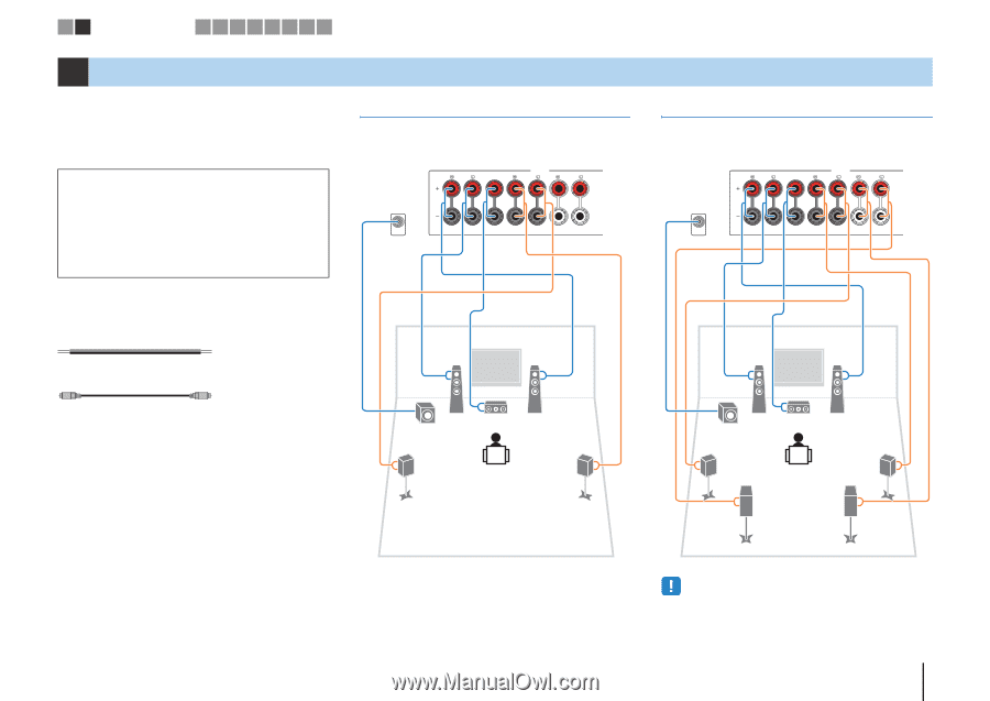
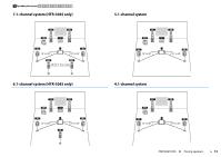
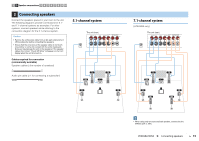
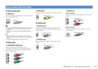
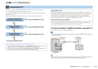
1 2 Speaker connections 3 4 5 6 7 8 9 10 2 Connecting speakers Connect the speakers placed in your room to the unit. The following diagrams provide connections for 5.1and 7.1-channel systems as examples. For other systems, connect speakers while referring to the connection diagram for the 5.1-channel system. Caution • Remove the unit's power cable from an AC wall outlet and turn off the subwoofer before connecting the speakers. • Ensure that the core wires of the speaker cable do not touch one another or come into contact with the unit's metal parts. Doing so may damage the unit or the speakers. If the speaker cables short circuit, "Check SP Wires" will appear on the front display when the unit is turned on. Cables required for connection (commercially available) Speaker cables (x the number of speakers) + + - - Audio pin cable (x1: for connecting a subwoofer) 5.1-channel system PB Y OR OUT The unit (rear) FRONT CENTER SPEAKERS SURROUND SURROUND BACK/BI AMP /ZONE B SINGLE SUBWOOFER 1 2 9 3 4 5 7.1-channel system (HTR-5065 only) PB Y OR OUT The unit (rear) FRONT CENTER SPEAKERS SURROUND SURROUND BACK/BI AMP /ZONE B SINGLE SUBWOOFER 1 2 9 3 4 6 5 7 • When using only one surround back speaker, connect it to the SINGLE jack (L side). PREPARATIONS ➤ Connecting speakers En 15
-
 1
1 -
2
-
3
-
4
-
5
-
6
-
7
-
8
-
9
-
 10
10 -
 11
11 -
 12
12 -
 13
13 -
 14
14 -
 15
15 -
 16
16 -
 17
17 -
 18
18 -
 19
19 -
 20
20 -
21
-
22
-
23
-
24
-
25
-
26
-
27
-
28
-
29
-
30
-
31
-
32
-
33
-
34
-
35
-
36
-
37
-
38
-
39
-
40
-
41
-
42
-
43
-
44
-
45
-
46
-
47
-
48
-
49
-
50
-
51
-
52
-
53
-
54
-
55
-
56
-
57
-
58
-
59
-
60
-
61
-
62
-
63
-
64
-
65
-
66
-
67
-
68
-
69
-
70
-
71
-
72
-
73
-
74
-
75
-
76
-
77
-
78
-
79
-
80
-
81
-
82
-
83
-
84
-
85
-
86
-
87
-
88
-
89
-
90
-
91
-
92
-
93
-
94
-
95
-
96
-
97
-
98
-
99
-
100
-
101
-
102
-
103
-
104
-
105
-
106
-
107
-
108
-
109
-
110
-
111
-
112
-
113
-
114
-
115
-
116
-
117
-
118
-
119
-
120
-
121
-
122
-
123
-
124
 |
 |