Yamaha HTR-4065 Owners Manual - Page 22
Connection Method 4 TV without HDMI input jacks
 |
View all Yamaha HTR-4065 manuals
Add to My Manuals
Save this manual to your list of manuals |
Page 22 highlights
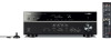
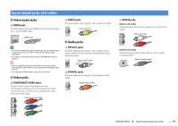
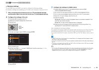
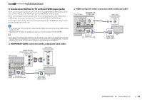
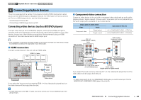
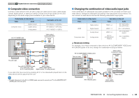
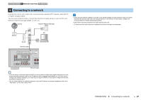
1 2 3 TV connection 4 5 6 7 8 9 10 ■ Connection Method 4 (TV without HDMI input jacks) When connecting any video device to the AV 1-2 (COMPONENT VIDEO) jacks of the unit, connect the TV to the MONITOR OUT (COMPONENT VIDEO) jacks. When connecting any video device to the AV 3-6 (VIDEO) jacks or the VIDEO AUX (VIDEO) jack of the unit, connect the TV to the MONITOR OUT (VIDEO) jack. If you select "AV 4" as the input source by pressing AV 4 or SCENE(TV), the TV audio will be played back on the unit. • If you connect your TV to the unit with a cable other than HDMI, video input to the unit via HDMI cannot be output to the TV. • Operations with TV screen are available only when your TV is connected to the unit via HDMI. • If you have connected any external device to the AV 4 jacks or if you want to use another input jack (other than OPTICAL) for connecting the TV, connect the TV to one of the AV 1-6 and AUDIO jacks. To use the SCENE function (p.35), you also need to change the input assignment for SCENE(TV). ❑ COMPONENT VIDEO connection (with a component video cable) MONITOR OUT (COMPONENT VIDEO) jacks The unit (rear) COMPONENT VIDEO PR PR HDMI OUT ARC HDMI 1 (BD/DVD) HDMI 2 HDMI 3 HDMI 4 PB PB Y Video input (component video) COMPONENT VIDEO PR PR PB PB Y Y ANTENNA AM FM COMPONENT VIDEO PR PB Y MONITOR OUT VIDEO Y MONITOR OUT COAXIAL AV 2 COAXIAL AV 3 OPTICAL ( TV ) AV 4 AV 5 OPTICAL AV 6 AV OUT SUBWOOFER AUDIO O (TV) AV 4 AV 4 (OPTICAL) jack OPTICAL O TV Audio output (digital optical) ❑ VIDEO (composite video) connection (with a video pin cable) The unit (rear) MONITOR OUT (VIDEO) jack HDMI OUT HDMI 1 (BD/DVD) HDMI 2 HDMI 3 HDMI 4 ARC PR V ANTENNA AM FM MOCONMVPIDIOETNOEONT R OUT PR PB PB Y COMPONENT VIDEO VIDEO Y MONITOR OUT OPTICAL AV 1 COAXIAL AV 2 COAXIAL AV 3 OPTICAL ( TV ) AV 4 AV 5 AV 6 AV OUT SUBWOOFER AUDIO O OPTICAL (TV) AV 4 AV 4 (OPTICAL) jack Video input (composite video) VIDEO V OPTICAL O TV Audio output (digital optical) PREPARATIONS ➤ Connecting a TV En 22
-
 1
1 -
2
-
3
-
4
-
5
-
6
-
7
-
8
-
9
-
10
-
11
-
12
-
13
-
14
-
15
-
16
-
 17
17 -
 18
18 -
 19
19 -
 20
20 -
 21
21 -
 22
22 -
 23
23 -
 24
24 -
 25
25 -
 26
26 -
 27
27 -
28
-
29
-
30
-
31
-
32
-
33
-
34
-
35
-
36
-
37
-
38
-
39
-
40
-
41
-
42
-
43
-
44
-
45
-
46
-
47
-
48
-
49
-
50
-
51
-
52
-
53
-
54
-
55
-
56
-
57
-
58
-
59
-
60
-
61
-
62
-
63
-
64
-
65
-
66
-
67
-
68
-
69
-
70
-
71
-
72
-
73
-
74
-
75
-
76
-
77
-
78
-
79
-
80
-
81
-
82
-
83
-
84
-
85
-
86
-
87
-
88
-
89
-
90
-
91
-
92
-
93
-
94
-
95
-
96
-
97
-
98
-
99
-
100
-
101
-
102
-
103
-
104
-
105
-
106
-
107
-
108
-
109
-
110
-
111
-
112
-
113
-
114
-
115
-
116
-
117
-
118
-
119
-
120
-
121
-
122
-
123
-
124
 |
 |