Yamaha HTR 5650 Owners Manual
Yamaha HTR 5650 - Digital Home Theater Receiver Manual
 |
UPC - 027108916460
View all Yamaha HTR 5650 manuals
Add to My Manuals
Save this manual to your list of manuals |
Yamaha HTR 5650 manual content summary:
- Yamaha HTR 5650 | Owners Manual - Page 1
U HTR-5650/HTR-5640 AV Receiver OWNER'S MANUAL - Yamaha HTR 5650 | Owners Manual - Page 2
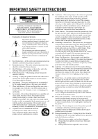
INSTRUCTIONS CAUTION RISK OF ELECTRIC SHOCK DO NOT OPEN CAUTION: TO REDUCE THE RISK OF ELECTRIC SHOCK, DO NOT REMOVE COVER (OR BACK). NO USER-SERVICEABLE PARTS INSIDE. REFER SERVICING TO QUALIFIED SERVICE or circuits. When installing an outside antenna system, extreme care should be taken to keep - Yamaha HTR 5650 | Owners Manual - Page 3
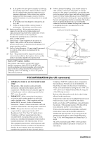
SERVICE GROUNDING ELECTRODE SYSTEM (NEC ART 250. PART H) FCC INFORMATION (for US customers) 1. IMPORTANT NOTICE : DO NOT MODIFY THIS UNIT! This product, when installed as indicated in the instructions contained in this manual, meets FCC requirements. Modifications not expressly approved by Yamaha - Yamaha HTR 5650 | Owners Manual - Page 4
manual carefully. Keep it in a safe place for future reference. 2 Install this sound system back of this unit. 3 Locate this unit away from other electrical appliances, motors, or transformers to avoid humming sounds to the user and/or YAMAHA service personnel when any service panel turned Owner's Manual - Yamaha HTR 5650 | Owners Manual - Page 5
Remote control 6 Front panel display 8 PREPARATION CONNECTIONS 9 Before connecting components 9 Connecting video components 10 Connecting audio components 12 Connecting the antennas 13 Connecting an external decoder 14 Connecting the speakers 15 Connecting the power supply cords 18 Turning - Yamaha HTR 5650 | Owners Manual - Page 6
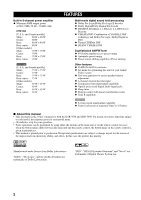
jacks N Sleep timer N Remote control with preset manufacturer codes N Zone B capability HTR-5650 N S-video signal input/output capability N Video Conversion (Composite Video ⇔ S Video) I About this manual • This document is the owner's manual for both the HTR-5650 and HTR-5640. For details on - Yamaha HTR 5650 | Owners Manual - Page 7
INTRODUCTION GETTING STARTED Supplied accessories After unpacking, check that the following parts are contained. Remote control CODE SET TRANSMIT POWER TV POWER AV STANDBY SYSTEM POWER CD MD/CD-R TUNER SLEEP DVD D-TV/CBL V-AUX 6CH INPUT VCR AMP ++ + TV VOL TV CH -- VOLUME - - Yamaha HTR 5650 | Owners Manual - Page 8
it in standby mode. When you turn the unit on, you will hear a click and there will be a 4 to 5-second delay before it can reproduce sound. Standby mode In this mode, the unit uses a small amount of power in order to receive infrared-signals from the remote control. 2 INPUT MODE Sets the priority - Yamaha HTR 5650 | Owners Manual - Page 9
to the speakers. e SPEAKERS A/B Turns the set of main speakers connected to the A and/or B terminals on or off. r STEREO/EFFECT Switches between normal stereo and DSP effect reproduction. When you select STEREO, the unit mixes down all Dolby Digital and DTS signals (except the LFE channel) as well - Yamaha HTR 5650 | Owners Manual - Page 10
speaker channel to adjust. 6 Multi control section Used to change and implement settings. 7 TEST Outputs a test tone for use when adjusting the speaker levels. 8 TRANSMIT indicator Flashes while the remote control is sending signals. 9 STANDBY Sets this unit in standby mode. 0 SYSTEM POWER Turns - Yamaha HTR 5650 | Owners Manual - Page 11
Digital and DTS signals (except the LFE channel) as well as those 2-channel signals without effect sounds, to the main left and right speakers. o NIGHT Sets the unit in night listening mode. p SET MENU Selects the set menu mode. CONTROLS AND FUNCTIONS I Using the remote control INPUT STANDBY - Yamaha HTR 5650 | Owners Manual - Page 12
appropriate sound channels light up when a digital signal from a source is played back. s RDS indicator (U.K. and Europe models only) The name(s) of the RDS data offered by the currently received RDS station light(s) up. EON indicator lights up when an RDS station that offers the EON data service is - Yamaha HTR 5650 | Owners Manual - Page 13
MAIN A B SPEAKERS L R REAR (SURROUND) L CENTER REAR CENTER 6CH INPUT jacks (page 14) DIGITAL OUTPUT jack (page 12) Antenna input terminals (page 13) SUBWOOFER OUTPUT jack (page 17) AC OUTLETS (page 18) All illustrations of the rear panel in this manual are based on the HTR-5650. The jacks - Yamaha HTR 5650 | Owners Manual - Page 14
components by using "INPUT 1 I/O ASSIGNMENT" on the set menu. HTR-5650 • Signals received through the S VIDEO input jacks can be converted to composite signals in unit, keep its power turned on while using this unit. If the power is off, this unit may distort the sound from other components. Signal - Yamaha HTR 5650 | Owners Manual - Page 15
O OPTICAL OUTPUT DVD player OPTICAL OUTPUT O L R AUDIO OUTPUT AUDIO VIDEO L R OUTPUT OUTPUT CONNECTIONS VIDEO OUTPUT TV/digital TV/ cable TV HTR-5650 AUDIO R L DIGITAL CD INPUT CD 5 COAXIAL 4 OPTICAL D-TV/CBL IN (PLAY) MD /CD-R OUT (REC) 3 DVD MAIN AUDIO R L VIDEO VIDEO - Yamaha HTR 5650 | Owners Manual - Page 16
CD-R jack on this unit to play a source from your recording component. HTR-5640 Connect the input jacks on your CD recorder or MD recorder to the MD keep its power turned on while using this unit. If the power is off, this unit may distort the sound from other components. HTR-5650 • The DIGITAL - Yamaha HTR 5650 | Owners Manual - Page 17
outdoor antenna may improve the quality. Consult the nearest authorized YAMAHA dealer or service center about the outdoor antennas. 3 Lead wire Cut the set the FREQUENCY STEP FREQUENCY STEP switch (located on the rear panel) according to the frequency spacing in your area. North, Central and - Yamaha HTR 5650 | Owners Manual - Page 18
left and right and SUBWOOFER) for discrete multi-channel input from a component equipped with a multi-channel decoder and 6 channel output jacks such as SURROUND SUBWOOFER MAIN DVD/SACD player Note • When you select 6CH INPUT as the input source, the unit automatically turns off the digital sound - Yamaha HTR 5650 | Owners Manual - Page 19
for reproducing the LFE (low-frequency effect) channel with high fidelity when playing back Dolby Digital or DTS signals. The YAMAHA Active Servo Processing Subwoofer System is ideal for natural and lively bass reproduction. CONNECTIONS I Speaker placement Refer to the following diagram when you - Yamaha HTR 5650 | Owners Manual - Page 20
, and if the polarity of the speaker connections is incorrect, the sound will be unnatural and lack bass. CAUTION • Use speakers with the specified impedance shown on the rear panel of this unit. • Do not let the bare speaker wires touch each other or any metal part of this unit. This could damage - Yamaha HTR 5650 | Owners Manual - Page 21
main left and right speakers by changing the setting of "SOUND 1 SPEAKER SET" item "1E BASS" on the set menu to MAIN. • Use the control on the subwoofer to adjust its volume level. You can also adjust the volume level by using this unit's remote control (see "SETTING THE SPEAKER LEVELS" on page 48 - Yamaha HTR 5650 | Owners Manual - Page 22
220/240 V AC, 50/60 Hz. CODE SET TRANSMIT POWER TV POWER AV STANDBY SYSTEM POWER CD MD/CD-R TUNER SLEEP DVD D-TV/CBL V-AUX 6CH INPUT VCR AMP 1 + TV VOL - TV MUTE + TV CH - TV INPUT + VOLUME - MUTE 1 Press STANDBY/ON (SYSTEM POWER on the remote control) to turn on the power of this - Yamaha HTR 5650 | Owners Manual - Page 23
See page 39). Altering any parameters in the BASIC menu will reset all parameters in the "SOUND" menu. Using the basic menu Use the remote control to make adjustments. • Press SPEAKERS A or B on the front panel to select the main speakers you want to use. • Make sure you disconnect headphones from - Yamaha HTR 5650 | Owners Manual - Page 24
BASIC SYSTEM SETTINGS SET MENU BASIC SOUND INPUT OPTION 1 SETUP Press j / i to alter the settings for each parameter. Use d to move to the next setting. 1 ROOM Choose from S/M/L. 2 SUBWOOFER Choose either of YES/NONE. 3 SPEAKERS Choose from 2/3/4/5/6 spk. CANCEL 4 SET/CANCEL Choose either - Yamaha HTR 5650 | Owners Manual - Page 25
to match your speaker system Follow the instructions below to set the amplifier output to match the size of your room and speakers. Press u the speakers in turn twice. • The indicator of the speaker currently outputting the test tone flashes on the front panel display. Setting speaker output levels - Yamaha HTR 5650 | Owners Manual - Page 26
CONCERT 3 ENTERTAINMENT 4 MUSIC VIDEO 5 TV MOVIE MOVIE THEATER THEATER 1 THEATER 2 6 7 8 /DTS SUR. 9 NIGHT 0 6.1/5.1 +10 STEREO ENTER EFFECT 6 1 Press STANDBY/ON (SYSTEM POWER on the remote control) to turn on the power. STANDBY /ON SYSTEM POWER or 4 Rotate the INPUT selector (or - Yamaha HTR 5650 | Owners Manual - Page 27
the current volume level as a bar graph. VOLUME + or VOLUME - Front panel Remote control If desired, use CONTROL and BASS/TREBLE -/+. These controls only effect the sound from the main speakers. CONTROL BASS/TREBLE Front panel Notes • If you increase or decrease the high-frequency or the - Yamaha HTR 5650 | Owners Manual - Page 28
wish to use. Each time you turn on the unit power, the input DTS are selected, even if the unit is receiving sound as 2-channel stereo from the main left and right speakers only. Therefore, you cannot adjust the level of the effect speakers while listening to such a source. I Notes on playing DTS - Yamaha HTR 5650 | Owners Manual - Page 29
CLUB 2 ROCK CONCERT 3 ENTERTAINMENT 4 MUSIC VIDEO 5 TV MOVIE MOVIE THEATER THEATER 1 THEATER 2 6 7 8 /DTS SUR. 9 NIGHT 0 6.1/5.1 +10 STEREO ENTER EFFECT PROGRAM l / h 1 Press AMP. CODE SET TRANSMIT POWER TV POWER AV STANDBY SYSTEM POWER CD MD/CD-R TUNER SLEEP DVD D-TV/CBL - Yamaha HTR 5650 | Owners Manual - Page 30
INPUT SPEAKERS A B STEREO EFFECT PROGRAM PRESET/TUNING FM/AM EDIT TUNING MODE MEMORY AUTO/MANUAL MONO MAN`L/AUTO FM A/B/C/D/E PRESET/TUNING NEXT SET MENU CONTROL BASS/TREBLE VOLUME VIDEO AUX VIDEO L AUDIO R PROGRAM l / h CODE SET TRANSMIT POWER TV POWER AV STANDBY SYSTEM POWER - Yamaha HTR 5650 | Owners Manual - Page 31
/EFFECT again to turn the sound effect back on. STEREO EFFECT Front panel STEREO or ENTER EFFECT Remote control PLAYBACK Notes • If you turn off the sound effects, no sound is output from the center speaker, rear speakers, or rear center speaker. • If you turn off the sound effects while the - Yamaha HTR 5650 | Owners Manual - Page 32
your listening room. The traditional stereo system that uses only two speakers is not capable of recreating a realistic sound field. YAMAHA's DSP requires four effect speakers to recreate sound fields based on the measured sound field data. The processor controls the strength and delay time of the - Yamaha HTR 5650 | Owners Manual - Page 33
-DSP sound field programs, YAMAHA's exclusive DSP processing is added to the Main left and right, and Center channels, so the listener can enjoy realistic dialogue, depth of sound, smooth transition between sound sources, and a surround sound field that goes beyond the screen. When a DTS or Dolby - Yamaha HTR 5650 | Owners Manual - Page 34
precisely. No DSP effect is applied in this program. This program ideally simulates the multi-surround speaker systems of the 35-mm film theaters. Dolby Pro Logic decoding, Dolby Digital decoding or DTS decoding and digital sound field processing create precise effects without altering the original - Yamaha HTR 5650 | Owners Manual - Page 35
the same quality of sound and sound localization that 6-channel soundtracks do. The built-in Dolby Digital or DTS decoder brings the professional-quality sound designed for movie theaters into your home. With this unit's MOVIE THEATER programs, you can use Dolby Digital or DTS technology to recreate - Yamaha HTR 5650 | Owners Manual - Page 36
6CH INPUT SPEAKERS A B STEREO EFFECT PROGRAM PRESET/TUNING FM/AM EDIT TUNING MODE MEMORY AUTO/MANUAL MONO MAN`L/AUTO FM A/B/C/D/E PRESET/TUNING NEXT SET MENU CONTROL BASS/TREBLE VOLUME VIDEO AUX VIDEO L AUDIO R 4 1 Rotate the INPUT selector (or press TUNER on the remote control) to - Yamaha HTR 5650 | Owners Manual - Page 37
SPEAKERS A B STEREO EFFECT PROGRAM PRESET/TUNING FM/AM EDIT TUNING MODE MEMORY AUTO/MANUAL MONO MAN`L/AUTO FM A/B/C/D/E PRESET/TUNING NEXT SET MENU CONTROL received turn off the colon (:) and then press PRESET/TUNING l to begin tuning toward lower frequencies. Memory back-up The memory back - Yamaha HTR 5650 | Owners Manual - Page 38
MENU CONTROL BASS/TREBLE VOLUME VIDEO AUX VIDEO L AUDIO R 34 1 Tune in to a station. See page 32 for tuning instructions. VCR V-AUX D-TV/CBL DVD MD/CD-R TUNER SP A TUNED A AM 1440 kHz When tuned to a station, the front panel display shows the frequency of the station received. 2 Press - Yamaha HTR 5650 | Owners Manual - Page 39
SPEAKERS A B STEREO EFFECT PROGRAM PRESET/TUNING FM/AM EDIT TUNING MODE MEMORY AUTO/MANUAL MONO MAN`L/AUTO FM A/B/C/D/E PRESET/TUNING NEXT SET MENU CONTROL PRESET/TUNING SET MENU or PRESET/CH - SELECT + Front panel Remote control 1,3 1,3 1 Select preset station "E1" by using the - Yamaha HTR 5650 | Owners Manual - Page 40
remote control. y • By connecting a commercially available timer to this unit, you can also set a wake-up timer. Refer to the operation instructions of the timer. I Setting the sleep timer CODE SET TRANSMIT POWER TV POWER AV STANDBY SYSTEM up on the front panel display soon after the sleep - Yamaha HTR 5650 | Owners Manual - Page 41
6CH INPUT SPEAKERS A B PHONES STEREO EFFECT PROGRAM PRESET/TUNING FM/AM EDIT TUNING MODE MEMORY AUTO/MANUAL MONO MAN`L/AUTO FM A/B/C/D/E PRESET/TUNING NEXT SET MENU CONTROL BASS/TREBLE VOLUME VIDEO AUX VIDEO L AUDIO R 2 CODE SET TRANSMIT POWER TV POWER AV STANDBY SYSTEM POWER - Yamaha HTR 5650 | Owners Manual - Page 42
and tone of the sound output by the system. 1 SPEAKER SET 2 SP DISTANCE (Speaker distance) 3 LFE LEVEL Adjusting the items on the set menu Use the remote control to make adjustments. VCR AMP ++ + TV VOL VIDEO 5 TV MOVIE MOVIE THEATER THEATER 1 THEATER 2 6 7 8 /DTS SUR. 9 NIGHT 0 - Yamaha HTR 5650 | Owners Manual - Page 43
. The unit directs all of the center channel signal to the main left and right speakers. The BASIC and SOUND menus The "BASIC" menu allows you to easily set the "SOUND 1 SPEAKER SET" and "SOUND 2 SP DISTANCE" parameters. It is not necessary to reset any of the parameters in the "BASIC" menu, but - Yamaha HTR 5650 | Owners Manual - Page 44
speakers or if a rear subwoofer is connected to the rear speakers. The entire range of the rear channel signal is directed to the rear left and right speakers center speaker mode) If you add a rear center speaker to your speaker configuration, this unit can provide more realistic frontto-back - Yamaha HTR 5650 | Owners Manual - Page 45
to adjust the output level of the LFE (low-frequency effect) channel when playing back a Dolby Digital or DTS signal. The LFE signal carries lowfrequency special effect sound which is only added to certain scenes. Control range: SPEAKER 20 to 0 dB HEADPHONE ..... -20 to 0 dB Initial setting: 0 dB - Yamaha HTR 5650 | Owners Manual - Page 46
that component with INPUT (or the input selector buttons on the remote control). I 1A for COMPONENT VIDEO INPUT jacks Choices: [A] DVD, VCR, V-AUX, D-TV/CBL [B] DVD, VCR, V-AUX, D-TV/CBL I 1B for OPTICAL OUTPUT jack HTR-5650 Choices: (1) MD/CD-R, CD, VCR, V-AUX, D-TV/CBL, DVD I 1C for - Yamaha HTR 5650 | Owners Manual - Page 47
the front panel display. Control range: -4 to 0 I V CONV. (Video conversion) HTR-5650 (With the exception of China and General models) Use this feature to turn on/off the conversion of composite signals to S-video signals to output through the S-video jack when the unit is receiving a video signal - Yamaha HTR 5650 | Owners Manual - Page 48
room. ZONE B Select this if the speakers connected to the SPEAKERS B terminals are set another room. If SPEAKERS A is turned OFF and SPEAKERS B is turned ON, all the speakers including the subwoofer in the main room are muted and the unit outputs sound from SPEAKERS B only. Notes • If you connect - Yamaha HTR 5650 | Owners Manual - Page 49
FEATURES In addition to controlling this unit, the remote control can operate other A/V components made by YAMAHA and other manufacturers. To control other components, set up the remote control with the appropriate manufacturer codes. Control area I Controlling this unit The shaded areas below - Yamaha HTR 5650 | Owners Manual - Page 50
component to be used. Refer to "LIST OF MANUFACTURER'S CODES" at the end of this manual. HALL 1 ROCK ENTER- JAZZ CLUB CONCERT TAINMENT 2 3 4 MUSIC VIDEO 5 TV MOVIE MOVIE THEATER THEATER 1 THEATER 2 6 7 8 /DTS SUR. 9 NIGHT 0 6.1/5.1 +10 STEREO ENTER EFFECT The TRANSMIT indicator - Yamaha HTR 5650 | Owners Manual - Page 51
remote control switches to the mode for operating the component. REMOTE CONTROL FEATURES 1 2 3 4 5 6 CODE SET TRANSMIT POWER TV POWER AV STANDBY SYSTEM 5 TV MOVIE MOVIE THEATER THEATER 1 THEATER 2 6 7 8 /DTS SUR. 9 NIGHT 0 *2TV power *2TV channel up *2TV channel down *2TV volume - Yamaha HTR 5650 | Owners Manual - Page 52
the volume of the speakers while listening to sound playback. 2 VCR AMP ++ + TV VOL TV CH -- VOLUME - TV MUTE TV INPUT MUTE HALL 1 ROCK ENTER- JAZZ CLUB CONCERT TAINMENT 2 3 4 MUSIC VIDEO 5 TV MOVIE MOVIE THEATER THEATER 1 THEATER 2 6 7 8 /DTS SUR. 9 NIGHT 0 6.1/5.1 +10 - Yamaha HTR 5650 | Owners Manual - Page 53
SET MENU MENU A/B/C/D/E + TEST RETURN DISPLAY 1 2 3 4 AMP 2 Select a sound field program. HALL 1 ROCK ENTER- JAZZ CLUB CONCERT TAINMENT 2 3 4 MUSIC VIDEO 5 TV MOVIE MOVIE THEATER THEATER 1 THEATER 2 6 7 8 /DTS SUR. 9 NIGHT 0 6.1/5.1 +10 STEREO ENTER EFFECT 3 Press u / d to - Yamaha HTR 5650 | Owners Manual - Page 54
center image towards the main left and right speakers. Control range: 0 (center channel sound is output only from center speaker) to 7 (center channel sound is output only from main left and right speakers), initial setting is 3. For DTS Neo:6 Music I C. IMAGE (Center Image) Function: This - Yamaha HTR 5650 | Owners Manual - Page 55
below or if the instruction below does not help, set this unit to standby mode, disconnect the power cord, and contact the nearest authorized YAMAHA dealer or service center. I General Problem Cause Remedy Refer to page This unit fails to turn on when STANDBY/ ON (or SYSTEM POWER) is pressed - Yamaha HTR 5650 | Owners Manual - Page 56
TROUBLESHOOTING Problem Only the speaker on one side can be heard. No sound from the effect speakers. No sound from the center speaker. No sound from the rear speakers. No sound from the subwoofer. Poor bass reproduction. Cause Incorrect cable connections. Remedy Refer to page Connect the - Yamaha HTR 5650 | Owners Manual - Page 57
TROUBLESHOOTING Problem Cause Remedy Refer to page No sound from the rear "SOUND 1C REAR LR" or "SOUND 1D Select LRG or SML. 40 center speaker. REAR CT" on the set menu is set to NON. The Dolby Digital EX or the DTS-ES Press 6.1/5.1 on the remote control to switch the - decoder is not - Yamaha HTR 5650 | Owners Manual - Page 58
antenna. - Use the manual tuning method. 32 control Problem Cause Remedy The remote control does Wrong distance or angle. not work nor function properly. The remote control will function within a maximum range of 6 m (20 feet) and no more than 30 degrees off-axis from the front panel - Yamaha HTR 5650 | Owners Manual - Page 59
theater system so that you can enjoy the depth of sound and natural spatial representation of DTS digital surround in your home. This system produces practically distortion-free 6-channel sound (technically, a left, right and center channels, 2 rear channels, plus an LFE 0.1 channel as a subwoofer - Yamaha HTR 5650 | Owners Manual - Page 60
I Virtual CINEMA DSP YAMAHA has developed a virtual CINEMA DSP algorithm that allows you to enjoy DSP sound field surround effects even without any rear speakers by using virtual rear speakers. It is even possible to enjoy virtual CINEMA DSP using a minimal 2-speaker system that does not include - Yamaha HTR 5650 | Owners Manual - Page 61
HTR-5650 115 W HTR-5640 110 W • Maximum Power (EIAJ) [China, Korea and General models] 1 kHz, 10% THD, 8 Ω HTR-5650 100 W HTR-5640 95 W • Dynamic Power (IHF) 8/6/4/2 Ω HTR-5650 or less • Channel Separation (1 kHz/10 kHz) CD (5.1 kΩ terminated) to Main L/R 60 dB/45 dB • Tone Control (Main L/R) - Yamaha HTR 5650 | Owners Manual - Page 62
LIST OF MANUFACTURER CODES LISTE DES CODES DES FABRICANTS TV A TANDY 0941 ABEX 1151 ADMIRA 1141 ADVENTURA 1131 AIKO 1121 AIWA 1481 AKAI 0331, 1101, 1111 ALBA 0431 ALLERON 1091 AMBASSADOR 1081 - Yamaha HTR 5650 | Owners Manual - Page 63
, 1031, 1091, 1111, 1771 WATSON 1001 XOGEGO 1611, 1621, 1661, 1741, 1761 YAMAHA 0361, 1031, 1111 YOKO 1001 ZENITH 0011, 0041, 0891, 0991, 1771 ZONDA 1161 0696 PIONEER BR90 0556 PULSAR 0386 RCA DIGITAL SATELLITE SYSTEM 0396, 0406 REALISTIC 0136 REGENCY/EASTERN 0686 RUNCO 0386 - Yamaha HTR 5650 | Owners Manual - Page 64
RESEARCH 0202, 0432, 0632 VIDEO CONCEPTS 0202, 0432, 0632, 0952 WARDS 0322, 0402, 0472, 0482, 0602, 0712, 0842, 0852, 0922, 0932, 0992 YAMAHA ZENITH 0202, 0632 0042, 0362, 0512, 0672 DVD PLAYER AKAI 0058 AIWA 0218 DENON 0188 HITACHI 0198 JVC (VICTOR) 0088, 0178 KENWOOD 0148 LG - Yamaha HTR 5650 | Owners Manual - Page 65
, 0114, 0164, 0174, 0264 CD RECORDER/CDRW HITACHI 0474 JVC (VICTOR) 0504 MARANTZ 0484, 0494 PHILIPS 0444 PIONEER 0454 YAMAHA 0414 MD RECORDER KENWOOD PIONEER SHARP SONY YAMAHA 0384 0424 0434 0394 0024, 0394, 0404, 0514 TAPE DECK AIWA 0094, 0214, 0224 AKAI 0184 CARVER 0094 DENON - Yamaha HTR 5650 | Owners Manual - Page 66
ELECTRONIQUE FRANCE S.A. RUE AMBROISE CROIZAT BP70 CROISSY-BEAUBOURG 77312 MARNE-LA-VALLEE CEDEX02, FRANCE YAMAHA ELECTRONICS (UK) LTD. YAMAHA HOUSE, 200 RICKMANSWORTH ROAD WATFORD, HERTS WD1 7JS, ENGLAND YAMAHA SCANDINAVIA A.B. J A WETTERGRENS GATA 1, BOX 30053, 400 43 VÄSTRA FRÖLUNDA, SWEDEN
-
 1
1 -
 2
2 -
 3
3 -
 4
4 -
 5
5 -
 6
6 -
 7
7 -
8
-
9
-
10
-
11
-
12
-
13
-
14
-
15
-
16
-
17
-
18
-
19
-
20
-
21
-
22
-
23
-
24
-
25
-
26
-
27
-
28
-
29
-
30
-
31
-
32
-
33
-
34
-
35
-
36
-
37
-
38
-
39
-
40
-
41
-
42
-
43
-
44
-
45
-
46
-
47
-
48
-
49
-
50
-
51
-
52
-
53
-
54
-
55
-
56
-
57
-
58
-
59
-
60
-
61
-
62
-
63
-
64
-
65
-
66
 |
 |

OWNER’S MANUAL
HTR-5650/HTR-5640
U
AV Receiver