Yamaha IM8-32 Owner's Manual
Yamaha IM8-32 Manual
 |
View all Yamaha IM8-32 manuals
Add to My Manuals
Save this manual to your list of manuals |
Yamaha IM8-32 manual content summary:
- Yamaha IM8-32 | Owner's Manual - Page 1
English Español Français Deutsch Italiano MIXING CONSOLE Owner's Manual Bedienungsanleitung Mode d'emploi Manual de instrucciones Manuale di istruzioni EN DE FR ES IT RU ZH JA - Yamaha IM8-32 | Owner's Manual - Page 2
not installed and used according to the instructions found in the users manual, may cause interference harmful to the Yamaha Corporation of America Address : 6600 Orangethorpe Ave., Buena Park, Calif. 90620 Telephone : 714-522-9011 Type of Equipment : MIXING CONSOLE Model Name : IM8-40/IM8-32/IM8 - Yamaha IM8-32 | Owner's Manual - Page 3
apparatus during lightning storms or when unused for long periods of time. 14 Refer all servicing to qualified service personnel. Servicing is required when the apparatus has been damaged in any way, such as power-supply cord or plug is damaged, liquid has been spilled or objects have fallen into the - Yamaha IM8-32 | Owner's Manual - Page 4
qualified Yamaha service personnel. • If this device or power supply should be dropped or damaged, immediately turn off the power switch, on the AC power in your audio system, always turn on the power amplifier LAST, to avoid speaker damage. When turning the power off, the power amplifier should - Yamaha IM8-32 | Owner's Manual - Page 5
turn the power off when the device is not in use. The performance of components with moving contacts, such as switches, volume controls, and connectors, deteriorates over time. Consult qualifi ed Yamaha service personnel about replacing defective components. SPECIAL NOTICES • This manual is the - Yamaha IM8-32 | Owner's Manual - Page 6
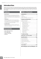
mix but also to create individual mixes for monitoring. Accessories • Owner's Manual (this book) • Power supply cable • Cubase AI 4 DVD-ROM • USB cable Introduction 6 Features 6 Accessories 6 System Requirements 7 Differences between the IM8-40/32/24 mixers 7 Controls and Functions 8 Channel - Yamaha IM8-32 | Owner's Manual - Page 7
channels (stereo input channels, 2TR IN, etc.) are the same for all models. • Number of LAMP connectors The IM8-40 provides three LAMP connectors to which you can connect separately sold gooseneck lamps (e.g., Yamaha LA5000), while the IM8-32 and IM8-24 provide two such connectors. Owner's Manual - Yamaha IM8-32 | Owner's Manual - Page 8
off the Yamaha PW8 power supply before you connect or disconnect any cables to or from the console. 1 INPUT Jack (monaural) These monaural input jacks are used to connect microphones or musical instruments. Each input channel features two types of jacks (INPUT A and INPUT B). • INPUT A Jack These - Yamaha IM8-32 | Owner's Manual - Page 9
Functions 5 +48V Switch/Indicator This switch toggles phantom power on and off for a monaural channel. When the switch is turned on, the +48V indicator will light, and DC +48V phantom power will be supplied to Pin 2 and 3 of the corresponding XLR-type INPUT A jacks. Turn this switch on when using - Yamaha IM8-32 | Owner's Manual - Page 10
. A fee will be charged for this modification. In this case, the signal will be sent to the AUX buses even if the input channel's ON switch is turned off. For details, contact to your Yamaha dealer listed at the end of this manual. E PAN Control This control determines the stereo positioning of the - Yamaha IM8-32 | Owner's Manual - Page 11
PFL indicator of the MONITOR section (page 18) will light. L Channel Fader Adjusts the output level of the input channel signal. Use these faders to adjust the balance between the various channels. NOTE · To minimize noise, the faders of unused channels should be set to the lowest position. · The - Yamaha IM8-32 | Owner's Manual - Page 12
(page 15) REC OUT/USB Section (page 14) MATRIX OUT Section (page 14) DC POWER INPUT Section (page 15) MUTE MASTER Section (page 15) TALKBACK Section (page 15) AUX SEND Section (page 16) MONITOR Section (page 18) GROUP OUT Section (page 16) 12 Owner's Manual MONO Section (page 19) STEREO - Yamaha IM8-32 | Owner's Manual - Page 13
inputting a stereo audio source. Use these jacks when you want to connect a CD player, and output the signal to the ST L/R or MONO bus. NOTE · If signals are simultaneously input from the 2TR IN jacks (RCA pin jacks, mini-phone jack) and the USB connector, the signals will be mixed. 2 USB Connector - Yamaha IM8-32 | Owner's Manual - Page 14
) to which the sig- nal received from the 2TR IN jacks and the USB con- nector is sent. 2 • ST switch: Sends the signal to the ST L/R bus. • MONO switch: Sends the mixed L and R signal to the MONO bus. 4 2TR IN/USB Control Adjusts the level of the signal received from the 2TR IN jacks and - Yamaha IM8-32 | Owner's Manual - Page 15
when the Yamaha PW8 power supply is connected to the console and the PW8 is turned on. MUTE MASTER Section Top Panel TALKBACK Section Rear Panel Top Panel 1 2 3 4 1 TALKBACK MIC IN Jack This is an XLR-3-31 type unbalanced input jack for connecting a talkback microphone. 2 Bus Assign Switches - Yamaha IM8-32 | Owner's Manual - Page 16
devices via an INSERT jack requires a special insert cable such as illustrated below (insert cable sold separately). To the input jack of the external processor To the INSERT jack Tip: OUT 16 Owner's Manual Sleeve (Ground) Ring: IN Tip: OUT Tip: IN To the output jack of the external processor - Yamaha IM8-32 | Owner's Manual - Page 17
recorder, external mixer, or other such device. 3 to the ST L/R bus. Rotate the knob clockwise Bus Assign Switches These switches assign the GROUP OUT signal to the ST L/R bus and the MONO bus ST L/R bus or MONO bus. 7 Panel 1 STEREO INSERT Jack This is an input/output jack located before the STEREO OUT - Yamaha IM8-32 | Owner's Manual - Page 18
insert cable such as illustrated below (insert cable sold separately). To the input jack of the external processor To the INSERT jack Tip: OUT Sleeve output the mixed stereo signal. They output the signal adjusted by the STEREO OUT master faders (7). Connect these jacks to the power amplifi Manual - Yamaha IM8-32 | Owner's Manual - Page 19
input jack of the external processor This is an XLR-4-31 type connector that supplies power to a separately sold gooseneck lamp (e.g., Yamaha LA5000). The IM8-40 mixer has three of these connectors, and the IM8-32/24 mixers , these output jacks are less affected by induced noise. Owner's Manual 19 - Yamaha IM8-32 | Owner's Manual - Page 20
the included power supply cable? The PW8 itself will not power-on unless it is correctly connected via the included power cable. • If the above checks do not identify the problem, call Yamaha for service. The sound of the bass drum will not move forward in the mix. • Could you be mixing a phase - Yamaha IM8-32 | Owner's Manual - Page 21
the written consent of the manufacturer. Yamaha makes no representations or warranties with regard to the use of the software and documentation and cannot be held responsible for the results of the use of this manual and the software. This disk is NOT for audio/visual purpose. Do not attempt to - Yamaha IM8-32 | Owner's Manual - Page 22
") WHICH IS BUNDLED WITH THIS PRODUCT. SINCE THE END-USER SOFTWARE LICENSE AGREEMENT (EUSLA) SHOWN ON YOUR PC-DISPLAY IN policy. · You may not initiate services based on the use of the SOFTWARE without permission by Yamaha Corporation. Copyrighted data, including but Yamaha. 22 Owner's Manual - Yamaha IM8-32 | Owner's Manual - Page 23
Owner's Manual 23 English - Yamaha IM8-32 | Owner's Manual - Page 24
maximum when measured. PAN/BAL: panned hard left or hard right. Rs = 150 Ω INPUT GAIN: max From MONO CH INPUT* INSERT OUT (MONO CH) DIRECT OUT (MONO CH) INSERT OUT (STEREO, GROUP, MONO impedance of signal generator: 150 ohms * IM8-40: 1-40, IM8-32: 1-32, IM8-24: 1-24 Italiano 166 Owner's Manual - Yamaha IM8-32 | Owner's Manual - Page 25
variable level. LAMP IM8-40: 3 pcs, IM8-32/24: 2pcs Signal Indicator LED Level Meter USB Audio Compressor Dimensions Net Weight MONO CH INPUT* MONO CH INPUT* ST CH INPUT MONO CH INPUT* ST CH INPUT 1-4 INSERT OUT GROUP and level controls are at their maximum positions.) Italiano Owner's Manual 167 - Yamaha IM8-32 | Owner's Manual - Page 26
600 Ω Lines 10 kΩ Lines 10 kΩ Lines 10 kΩ Lines 10 kΩ Lines 10 kΩ Lines 40 Ω Phones Nominal Level +4 dBu (1.23 V) +4 dBu (1.23 V) +4 dBu (1.23 V) +4 Input/Output Specifications Connector USB Format USB AUDIO 1.1 Data Length 16 bit Connector Specifications USB B type Italiano 168 Owner's Manual - Yamaha IM8-32 | Owner's Manual - Page 27
Sleeve: Ground Tip: L Ring: R Sleeve: Ground INPUT A (stereo), AUX RETURN, DIRECT OUT Tip: Hot Sleeve: Ground Specifications Configurations INPUT 132 OUTPUT 231 XLR-3-31/XLR-3-32 Jack 23 1 4 XLR-4-31 Jack Ring Sleeve Tip TRS Phone Jack Sleeve Tip Phone Jack Italiano Owner's Manual 169 - Yamaha IM8-32 | Owner's Manual - Page 28
English 113 Español Français Deutsch Specifications Dimensional Diagram IM8-40 198 1320 198 H: 219 17 IM8-32 198 W: 1716 1075.5 Units: mm 198 H: 219 17 D: 739 495 131 Italiano 113 D: 739 495 131 170 W: 1471.5 Owner's Manual Units: mm - Yamaha IM8-32 | Owner's Manual - Page 29
English Español Français Deutsch IM8-24 198 831 198 Specifications H: 219 17 113 D: 739 495 131 W: 1227 Units: mm Italiano Owner's Manual 171 - Yamaha IM8-32 | Owner's Manual - Page 30
MIXING CONSOLE Monaural Input Track Sheet Stereo Input 1 1 172 Owner's Manual - Yamaha IM8-32 | Owner's Manual - Page 31
Title: Date: Place: Session Information Notes: 1 2 3 4 1 2 3 4 1 2 3 4 5 6 7 8 Owner's Manual 173 - Yamaha IM8-32 | Owner's Manual - Page 32
GROUP OUT [+4dBu] ST, MONO, AUX INSERT I/O [0dBu] ST, MONO, AUX Fader [Nominal:-10dB] USB OUT(L) USB OUT(R) LPF [0dBu] LPF USB IN(L) USB IN(R) LPF [0dBu] LPF LIN USB D- RIN AUDIO D+ LO GND RO ( Bus Powered) Vbus USB Clip Level (ST, MONO, AUX) Clip Level (REC OUT) ST OUT, MONO OUT, AUX - Yamaha IM8-32 | Owner's Manual - Page 33
3-9693-5111 COUNTRIES AND TRUST TERRITORIES IN PACIFIC OCEAN Yamaha Corporation, Asia-Pacific Music Marketing Group Nakazawa-cho 10-1, Naka-ku, Hamamatsu, Japan 430-8650 Tel: +81-53-460-2313 PA20 HEAD OFFICE Yamaha Corporation, Pro Audio & Digital Musical Instrument Division Nakazawa-cho 10-1, Naka - Yamaha IM8-32 | Owner's Manual - Page 34
Yamaha Pro Audio global web site: http://www.yamahaproaudio.com/ Yamaha Manual Library http://www.yamaha.co.jp/manual/ U.R.G., Pro Audio & Digital Musical Instrument Division, Yamaha Corporation ©2008 Yamaha Corporation WN16170 805 IPDHx.x-01A0 Printed in Japan
-
 1
1 -
 2
2 -
 3
3 -
 4
4 -
 5
5 -
 6
6 -
 7
7 -
8
-
9
-
10
-
11
-
12
-
13
-
14
-
15
-
16
-
17
-
18
-
19
-
20
-
21
-
22
-
23
-
24
-
25
-
26
-
27
-
28
-
29
-
30
-
31
-
32
-
33
-
34
 |
 |

IT
RU
ZH
JA
ES
FR
DE
EN
MIXING CONSOLE
Owner’s Manual
Bedienungsanleitung
Mode d’emploi
Manual de instrucciones
Manuale di istruzioni
English
Italiano
Español
Français
Deutsch