Yamaha MCR-040 Owners Manual
Yamaha MCR-040 Manual
 |
View all Yamaha MCR-040 manuals
Add to My Manuals
Save this manual to your list of manuals |
Yamaha MCR-040 manual content summary:
- Yamaha MCR-040 | Owners Manual - Page 1
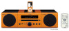
AB MICRO COMPONENT SYSTEM OWNER'S MANUAL - Yamaha MCR-040 | Owners Manual - Page 2
Replace only with the same or equivalent type. Radio waves may affect electro-medical devices. Do not use MCR-140 near medical devices or inside medical facilities. Do not use MCR-140 within 22 cm (9 in) of persons with a heart pacemaker implant or defibrillator implant. We, the manufacturer Yamaha - Yamaha MCR-040 | Owners Manual - Page 3
and sleep timer 16 ADDITIONAL INFORMATION TROUBLESHOOTING 17 General 17 DAB reception 18 FM reception 18 iPod 19 USB 21 Disc playback 22 Remote control 22 HANDLING COMPACT DISCS 23 SPECIFICATIONS 23 ADDITIONAL INFORMATION ■ About this manual • This manual describes how to operate this - Yamaha MCR-040 | Owners Manual - Page 4
following items. MCR-040 CD receiver (CRX-040) Dock cover PARTS + Speakers (NS-BP80) MCR-140 CD receiver (CRX-140) Cover the iPod dock when not using. Transmitter Remote control Speaker cable (1.5 m (4.9') × 2) + ■ Using the remote control Within 6 m (20') Use the remote control within - Yamaha MCR-040 | Owners Manual - Page 5
discs on which recording was not made correctly. .... CD-TEXT discs To play back an 8-cm (3 in) CD Place it in the inner recessed area of constant and variable bitrates are supported. Notes • Playback for Data Disc starts in alphanumeric order of files. • Playback for USB starts in order by date - Yamaha MCR-040 | Owners Manual - Page 6
the height, direction, or placement of the antenna. Notes • Be sure to connect the left channel (L), right channel (R), "+"(red) "-"(black) properly. If the connections are faulty, no sound will be heard from the speakers, and if the polarity of the speaker connections is incorrect, the sound - Yamaha MCR-040 | Owners Manual - Page 7
supplied with the iPod or an iPod Universal Dock Adapter (sold separately), and remove the protective case covering your iPod. MCR-140 Station your iPod in the charging cradle when you want to charge your iPod. You can also control your iPod with the remote control when your iPod is in the charging - Yamaha MCR-040 | Owners Manual - Page 8
indicator: Lights up when you set your iPod (MCR-040)/CD/USB to shuffle play (☞ P. 9). 6 REPEAT indicator: Lights up when you set your iPod (MCR-040)/CD/USB to repeat play (☞ P. 9). 7 Radio Data System indicators: The name of the Radio Data System data offered by the currently received Radio Data - Yamaha MCR-040 | Owners Manual - Page 9
not output sound for a certain period, the unit will automatically switch to standby mode (MCR-140 only). MCR-140 iPod dock MCR-040 : Unit standby/on USB port: ☞ P. 5, 8 iPod USB PORTABLE VOLUME INPUT Charging cradle Disc tray : Disc tray open/close : Play/pause playback : Stop playback - Yamaha MCR-040 | Owners Manual - Page 10
back music. 1 Set the source MCR-040 2 Switch the input Dock Adapter 3 Select music and start playback Scroll the list Control menu iPod*1 MCR-140 ☞ P. 5 For the MCR-140, the operation on the remote control Yamaha and suppliers accept no liability for the loss of data saved on the USB devices - Yamaha MCR-040 | Owners Manual - Page 11
OPERATION Other operation ■ Control playback 1 2 During playback LISTENING TO MUSIC ■ Switching Press repeatedly. For iPod MCR-040 Song number and elapsed time (default setting) ↓ Song number and remaining time ↓ Song name ↓ Artist name ↓ Album name ↓ Back to the default setting Note - Yamaha MCR-040 | Owners Manual - Page 12
scan must be performed. The initial scan starts automatically when you select DAB as the input source for the first time. Press repeatedly to select the DAB mode. y You can also perform the initial scan manually by INIT SCAN (☞ P. 13, 15). While the scan is in progress, "Scanning" and the percentage - Yamaha MCR-040 | Owners Manual - Page 13
as the name of the song, artist and speaker, etc. This data is continuously updated by format of the current station, and whether DRC (Dynamic Range Control)* is activated. "(DRC ON)" is displayed when DRC MODE by DRC MODE (☞ P. 13, 15). ↓ Back to the STATION LABEL Note Not all DAB broadcasters - Yamaha MCR-040 | Owners Manual - Page 14
tune into FM stations manually by pressing TUNING repeatedly. Note If you tune to a station manually, the sound is System information (U.K. model only) 1 2 While listening Press repeatedly. PS (Program Service) ↓ PTY (Program Type) ↓ RT (Radio Text) ↓ CT (Clock Time) ↓ Frequency ↓ Back - Yamaha MCR-040 | Owners Manual - Page 15
control range (Displays only when the input input source is set to DAB.) 15 DIMMER DIMMER ON (25%)/OFF (100%) 14 TREBLE -6 dB to +6 dB 14 BASS -6 dB to +6 dB MCR-140 GROUP A1/A2/A3/B1/B2/B3 5 POWER SAVING MCR-140 NORMAL/ECO 14 WIRELESS SW MCR-140 NO/YES 14 *1 When the input go back to - Yamaha MCR-040 | Owners Manual - Page 16
each left and right speaker channel. POWER SAVING: MCR-140. WIRELESS SW: Set to YES when you use a subwoofer via the wireless subwoofer set to standby mode automatically. Input source and track/file number or not exist, the first track/file is played back automatically. FM: Set preset number. By - Yamaha MCR-040 | Owners Manual - Page 17
preset settings cannot be restored. INIT SCAN: Performs the initial scan manually. Each time you perform INIT SCAN, the newly received stations are DAB signal (from 0 (none) to 100 (best)). Adjust the DAB/ FM antenna to find the best position to receive the DAB signal. y To check the frequency - Yamaha MCR-040 | Owners Manual - Page 18
sleep timer ■ Using the timer The timer sets the unit to play back music at the time you set. The unit is set to standby mode after the specified running time elapses. To use the timer, set the appropriate input source securely and set the timer in the setup menu in advance - Yamaha MCR-040 | Owners Manual - Page 19
TROUBLESHOOTING Refer to the table below when this unit does not function properly. If the problem you are experiencing is not listed below or if the instruction below does not help, turn off this unit, disconnect the power cable, and contact the nearest authorized Yamaha dealer or service - Yamaha MCR-040 | Owners Manual - Page 20
of FM stereo broadcasts may cause this problem when the transmitter is too far away or the antenna input is poor. The signal is too weak. The preset (memory) may have been erased. Remedy Change the height, direction, or placement of the antenna. Use the manual tuning method. Change the height - Yamaha MCR-040 | Owners Manual - Page 21
you are using MCR-040. Status message iPod Connecting iPod Charging Unknown iPod iPod iPod Unplugged Cause This unit is in the middle of recognizing the connection with your iPod. There is a problem with the signal path from your iPod to this unit. The iPod being used is not supported by this unit - Yamaha MCR-040 | Owners Manual - Page 22
the iPod. The unit cannot be operated by the remote control. You cannot operate from the iPod. The playback information is not displayed on the front panel display. The iPod does not charge up. MCR-040: The iPod is set in the iPod dock improperly. MCR-140: The iPod is connected to the transmitter - Yamaha MCR-040 | Owners Manual - Page 23
Problem Suddenly the speaker produces sound even though an iPod is not connected. Transmitted sound is cut. Cause MCR-140: The unit is connected to another transmitter. MCR-140: If noise occurs at the same frequency the transmitter is using, the unit will search and move to another (unused) - Yamaha MCR-040 | Owners Manual - Page 24
not contain sufficient music files to be played back. The sampling rate of an MP3 or supported by the unit. Remove the disc and then wipe the disc clean. Remove the disc and then load the disc with the labeled side facing up. Page 3 - - - - 3 3 - 3 - 3 - - Remote control Problem The remote control - Yamaha MCR-040 | Owners Manual - Page 25
of a disc. SPECIFICATIONS ■ CD RECEIVER (CRX-040, CRX-140) PLAYER SECTION iPod • Supported iPod.......iPod (5th USB • Audio format MP3, WMA PORTABLE • Input connector .......... STEREO L/R: 3.5 mm STEREO mini Jack AMPLIFIER SECTION • Maximum output power 15 W + 15 W (6 Ω 1 kHz, 10% THD) • Input - Yamaha MCR-040 | Owners Manual - Page 26
product needs guarantee service, please contact the dealer from whom it was purchased. If you experience any difficulty, please contact Yamaha representative office in your country. You can find full details on our website (http://www.yamaha-hifi.com/ or http://www.yamaha-uk.com/ for U.K. resident - Yamaha MCR-040 | Owners Manual - Page 27
controls or and an appropriate 3 pin plug fitted. For details, refer to the instructions described below. Note The plug severed from the mains lead must be or coloured BLACK. The wire which is coloured BROWN must be connected to the terminal which is marked with the letter L or coloured RED. Make - Yamaha MCR-040 | Owners Manual - Page 28
Printed in China WS48500
-
 1
1 -
 2
2 -
 3
3 -
 4
4 -
 5
5 -
 6
6 -
 7
7 -
8
-
9
-
10
-
11
-
12
-
13
-
14
-
15
-
16
-
17
-
18
-
19
-
20
-
21
-
22
-
23
-
24
-
25
-
26
-
27
-
28
 |
 |

OWNER’S MANUAL
AB
MICRO COMPONENT SYSTEM