Yamaha MR1642 Service Manual
Yamaha MR1642 Manual
 |
View all Yamaha MR1642 manuals
Add to My Manuals
Save this manual to your list of manuals |
Yamaha MR1642 manual content summary:
- Yamaha MR1642 | Service Manual - Page 1
MIXING/NM CONSOLES d=ft IMrmaM I= W SMN M MM IMP I=W WWI i fL 1) Q= fi MOM IN dMa ROI& M M MP ANIMM E. ffi = Mr IMM = M = MI= M M Lia SERVICE MANUAL BOARDS ( v - h 4* ) 12 DISASSEMBLY PROCEDURE(-5-1W*IIIR) 24 PARTS LIST YAMAHA CORP. HAMAMATSU, JAPAN 3.1K-613 0 Printed in Japan '89.8 - Yamaha MR1642 | Service Manual - Page 2
MR1242/MR1642 IMPORTANT NOTICE This manual has been provided for the use of authorized Yamaha Retailers and their service personnel. It has been assumed that basic service procedures inherent to the industry, and more specifically Yamaha Products, are already known and understood by the users, and - Yamaha MR1642 | Service Manual - Page 3
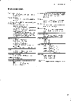
sold. Power Consumption MR842 :70 W MR1242 : 70 W MR1642 : 70 W Console Dimensions (W x H x D) MR842 : 555 x 182 x 600 mm (21-7/8" x 7-3/16' x 23-5/8') MR1242 : 695 x 182 x 600 mm (27-3/8' x 7-3/16" x 23-5/8") MR1642 : 835 x 182 x 600 mm (32-7/8' x 7-3/16' x 23-5/8") Net Weight MR842 : 15 Kg (33 - Yamaha MR1642 | Service Manual - Page 4
= 10kQ 10 Ica AUX RETURN (1, 2) stereo 10 kit INSERT IN MR84 CH [ MR1242 MR1642 :1---12 :1-16 GROUP (1-4) 10 kg2 50-600 52 -80dB (0.08mV) -60dB (0.8mV) -34dB (15. R) AUX SEND (1-3) MR842 :1-8 INSERT OUT CH [ MR1242 :1-16) GROUP (1-4) MONITOR OUT (L, R) PHONES OUT 150 52 600 Q 150 52 600 - Yamaha MR1642 | Service Manual - Page 5
mix level controls -minimum AUX SEND -64dB (68dB S/N) AUX SEND Master level control -*nominal One CH mix Input Level Nominal Connector In Max. befor clip Mixer 50 - 600 n Mics -80dB (0.08mV) OUT CH(1x) GROUP(1 4) MONITOR OUT (L, R) PHONE OUT Actual MR1642=16 -t•i4-11/Tto MR842/MR1242 - Yamaha MR1642 | Service Manual - Page 6
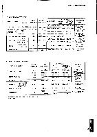
MR1642 "PANEL LAYOUT (i - Yamaha MR1642 | Service Manual - Page 7
/MR1242/MR1642 LO AUX I *3 I I AUX 2 ,er AUX 3 °0r':•C°UE CH INPUT (CH2-8. 12.16) SAME AS CHI Pe AUX 3 SU IN 0,0 'Ag4 CUE j, 0 11 GROUP I 1- •-• 100=se 41 CC CC 14 L11 4.1 T. 1ft0 0 se 0 MONITOR SELECT MONITOR • 0 A0PHONE L MONITOR OUT(44) R STEREO R DR +20 +10 a PAD -20/CAIN MIN - Yamaha MR1642 | Service Manual - Page 8
LAYOUT (.a_ •i h 1, 4 7 ,7 h ) MR842 • Front Panel (7 a ;/ , - Yamaha MR1642 | Service Manual - Page 9
DIMENSIONS (-t MR 842 555 MR1242 695 MR1642 835 -J 0 0 0 0 O O O O 00 0 00 0 0 O O O -J 0 -J -J O O O -J -J 0 O O O000 -J -J -J I I 0 0 000 O 0 -1 -J -1 -I -I _I I 1 II I I l!J I 0610 0 O 0 O O 0 0 0 0 OOO0 OM' 101 CIO lO OO 0 I MIC BLOCK DIAGRAM (IC 'in • NJM4558DV - Yamaha MR1642 | Service Manual - Page 10
4700pF DC500V (HX802090) 4700pF DC250V (HX802080) 1000 µF 100V (FL299100) 3300 µF 35V (FL259330) MR842 MR1242 MR1642 A circuit board Ch, 1-Ch. 7 Ch, 1 -Ch. 11 Ch, 1-Ch. 15 Al circuit board Ch. 8 Ch.12 Ch.16 " The Al circuit board is essentially the same as a A circuit board. The difference of Al - Yamaha MR1642 | Service Manual - Page 11
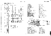
MR842/MR1242/MR1642 MR842/M R1242/M R1642 •MR -C1 & MR-C:2 Circuit Boards CUE PAN AUX RTN1,2 34 11-2 I /ZS 1 W13W12 I I O• C320 3•". ' IP- I (ip (4; ) elg41O k g...11 cC32 2 dG kr> a 1 ;i t0 t - Yamaha MR1642 | Service Manual - Page 12
MR842/MR1242/MR1642 MR842/MR1242/MR1642 •MR-E Circuit Board MR- E 0 OG Cs -,ti u 1 I I 1 TC42.53° i CT14!PS II I I MN 161-16/3I I C`I C11 R; N al I I I f'....' I lef. :A 1C'I: ) CUE Notes) • Circuit Board: MR-F (NX806700) ST-L, MONITOR IC IC 203, 205, 602: IC 601: 2. Transistor Q - Yamaha MR1642 | Service Manual - Page 13
MR842/MR1242/MR1642 MR842/MR1242/MR1642 •MR-G Circuit Board MR -C WI3 I2 3 2 C220N N N I t .41 1 1 ••• I N 4/. - Yamaha MR1642 | Service Manual - Page 14
MR842/MR1242/MR1642 MR842/MR1242/MR1642 •MR-I Circuit Board MR- I C34.1 . :k373 • 8375 • R377. • . --t4-- D301 -44D303 C343 p • L301 SW3C13 D305 C339 C340 R.367 R368 1365 a 8366 R363 Q303Q304: ::1:164. R361 - Yamaha MR1642 | Service Manual - Page 15
MR842/MR1242/MR1642 •MR-M Circuit Board AUX SEND 1 •+4dB 1 2 3 Notes) " Circuit Board: MR-M (NX806770) AUX SEND 1. MIC Jack J 511, 541, 571: RDJ (1C224010) 56V 1W (1X802970) 10KB 3P (HX802050) O.0047µ F 100V (HX802060) 0.1p, F 100 V (HX802070) 100 µ, F 100V (FJ298100) 22 R842/MR1242/MR1642 - Yamaha MR1642 | Service Manual - Page 16
R100 T4 En c, v1 N.O1 al en Components side (f9,341,0J) •MR-Q Circuit Board MONITOR OUT • +4dB L R Notes) • Circuit Board: MR-P (NX806800) • Circuit Board: MR Ch, 1-Ch. 8 X MR1242 Ch, 1-Ch. 12 X MR1642 Ch, 1 -Ch. 12 Ch.13-Ch.16 • The P1 circuit board is essentially the same as a P - Yamaha MR1642 | Service Manual - Page 17
MDISASSEMBLY PROCEDURE (53.1*jip) MR842/MR1242/MR1642 1. Removal of Bottom Board • Remove the 14 bind tapping screws OA ..,.0..4.a,a0a0.040)(0*.A06a) _ 0 WA 0 NA ME - Knob, Volume ("ti - Hexagonal Nut (AA T ) Fig. 2 0 0 O O O O O O 0 OOOOO O O MR-Al O O O O O O Fig. 3 24 MR842/MR1242/MR1642 - Yamaha MR1642 | Service Manual - Page 18
MR842/MR1242/MR1642 3. Removal of MR-C1, MR-C2 & MR-F Circuit Boards • Pull out the 2 volume (Fig.4) 6 . F OM- L75 • 4'9e7.1-N'YV:','CILA',4 AfTI ) (Fig.2) • laigAt- t • ( 1xiVil.3,) • 9 r h°:/7 .77. 0 (3 x 8) 3*t .AL, MR-G:i- (Fig.4) O O O O O O © OF 0 25 Fig. 4 R842/MR1242/MR1642 - Yamaha MR1642 | Service Manual - Page 19
MR842/MR1242/MR1642 7. Removal of MR-B Circuit Board • Remove the Bottom board. (see procedure 1) • Remove the 4 bind tapping screws ®(3x8), the MR-B circuit board can be removed. (Fig.5) 8. - Yamaha MR1642 | Service Manual - Page 20
MR842/MR1242/MR1642 11. Removal of MR-J, J1, J2, K, M, 0, P, P1 and -J1 0000000 ._0 " (0) r_3 00 oc oc *.. goo %.,W' 0 00 000 --, --- MR-J = Hexagonal Nut (All t ) Fig. 8 Note) MR842 MR1242 MR1642 P circuit board Ch, 1 -Ch. 8 Ch, 1-Ch. 12 Ch, 1-Ch. 12 P1 circuit board X X Ch.13-Ch - Yamaha MR1642 | Service Manual - Page 21
(MR842/MR1242/MR1642Vgian) J K L 0 Q MR842/MR1242/MR1642 MR - P T4 O (no fn cr 3 If) N NT," M vt ct WI 5G 5R 5W c.D 6P TIO OR MR- 1-1 T43 134 0 10I vu YE T8 RE T8 8P , BE' GY OR WI9 BL W16 BL • W 16 W18 W15 W 15 BL MR- B 1/2 T34 BL BR RE 2 3 OR T9 4 YE 5 GR 6 BE VI T9 8P •W - Yamaha MR1642 | Service Manual - Page 22
MR842/MR1242/MR 1 6424.0MO) K L M N 0 Q MR842/MR1242/MR1642 I II I I INPUT J 101 LO - Z PHANTOM J MSc ammo 25 2 5 K 100 10573A 4556DR582 C578 100/16 R570 100 C577 lOP IC572 A 4558 DY B MIC Jack J 601, 602: F6DJ-245 (LX801230) MONITOR OUT U.S. Model BE POWER SW FUSE BL YE BE
-
 1
1 -
 2
2 -
 3
3 -
 4
4 -
 5
5 -
 6
6 -
 7
7 -
8
-
9
-
10
-
11
-
12
-
13
-
14
-
15
-
16
-
17
-
18
-
19
-
20
-
21
-
22
 |
 |
MIXING/NM
CONSOLES
d=ft
I=
IM
W
rmaM
i
fL
1)
Q=
fi
S
MN
M
MM
IMP
I=W
WWI
MOM
ANIMM
ffi
=
E
.
IN
Mr
dMa
IMM
ROI&
=
-
M
=
M
MI=
M
M
M
MP
Lia
SERVICE
MANUAL
0
..
*
0,0
"
0
6
6
"6
*
4:
1
1
,
6
8
6
0
0.
0
0
0
0
0
0
0
6
0
anliall
******0•0*********
tal
1110
in
Mil
EMI
MI
11111
IN
IN
BB
El
III
Ill III
MI
ECONTENTS
(
)
SPECIFICATIONS
(4e*l±a)
2
PANEL
LAYOUT
(/
-1
7
r,
)
6
BLOCK
&
LEVEL
DIAGRAM
(
7‘
.
&
7
A)
8
CIRCUIT
BOARD
LAYOUT
(3_::
-(7
r
7
F
)
10
DIMENSIONS
(7k:A
)
1
1
IC
BLOCK
DIAGRAM
(ic
"ln
LI)
11
12
DISASSEMBLY
PROCEDURE
(
-
5-1W*IIIR)
24
PARTS
LIST
CIRCUIT
BOARDS
(
v -
h
4*
)
LM
006910
YAMAHA
CORP.
HAMAMATSU,
JAPAN
3.1K-613
0
Printed
in
Japan
'89.8