Yamaha PSR-9000 Owner's Manual - Page 162
Installing Options/Installationsoptionen/Installation des options, Vergewissern Sie sich
 |
View all Yamaha PSR-9000 manuals
Add to My Manuals
Save this manual to your list of manuals |
Page 162 highlights
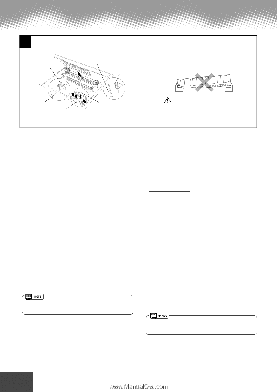
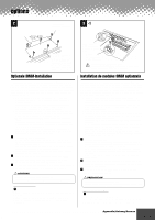
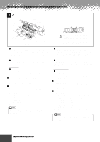
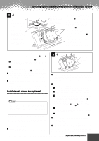
Installing Options/Installationsoptionen/Installation des options 3 -2 • Lug • Feder • Tenon A • SIMM hole • SIMM-Loch • Fente de SIMM • Lug • Feder • Tenon C B • SIMM hole • SIMM-Loch • Fente de SIMM • Slot protrusion • Slot protrusion • Saillie de connecteur • SIMM notch • SIMM-Kerbe • Encoche de SIMM • Make sure that the entire length of the SIMM is evenly inserted. • Stellen Sie sicher, daß die ganze Länge des SIMM-Moduls gleichmäßig • Veillez à ce que le module soit inséré uniformément sur toute sa longueur. c-2 Install the first SIMM in the rear slot (the slot closest to the PSR9000 rear panel), inserting it at an angle as shown in the illustration. Make sure that the parts at locations A, B, and C are properly aligned. c-3 Holding both edges of the SIMM module, raise it to the vertical position until it is firmly clamped by the left and right stoppers. Second SIMM c-4 After confirming the orientation, insert the second SIMM into the front slot (the slot closest to the PSR-9000 keyboard), and raise it to the vertical position in the same way as the first SIMM. v Replace the SIMM cover and attach it with the six screws. Set the PSR-9000 right-side up, and connect the power cord to the rear-panel AC INLET jack and an AC outlet. b Check that the installed SIMMs are functioning properly. Turn on the power, go to the SAMPLING display (page 41), and check that the REMAIN TIME value matches the amount of installed memory, as follows: 4MB x 2 8MB x 2 16MB x 2 32MB x 2 No SIMMS 106.9s 202.1s 392.3s 772.7s 11.8s (These values apply when there is no data in the wave memory.) • Although the wave memory of the PSR-9000 can be expanded to 65 megabytes, the maximum size of a single sample recording is 32 megabytes (380 sec.). c-2 Installieren Sie das erste SIMM-Modul in den hinteren Steckplatz (den der PSR-9000 Rückseite nächsten Schlitz), und stekken Sie es in einem Winkel ein, wie in der Abbildung gezeigt. Vergewissern Sie sich, daß die Teile an den Punkten A, B und C richtig ausgerichtet sind. c-3 Halten Sie beide Kanten des SIMM-Moduls, und heben Sie es in eine senkrechte Position, bis es von der linken und rechten Feder festgeklemmt ist. Zweites SIMM-Modul c-4 Nach dem Überprüfen der Ausrichtung stecken Sie das zweite SIMM-Modul in den vorderen Steckplatz (den der PSR-9000 Tastatur nächsten Schlitz), und heben Sie es wie das erste SIMM-Modul in die senkrechte Position. v Setzen Sie die SIMM-Abdeckung auf, und befestigen Sie diese mit den sechs Schrauben. Stellen Sie das PSR-9000 wieder richtig herum auf, und schließen Sie das Netzkabel mit der rückseitigen AC INLET-Buchse und einer Steckdose an. b Überprüfen Sie, ob die installierten SIMM-Module richtig funktionieren. Schalten Sie das Gerät an, wechseln Sie zum SAMPLING-Display (Seite 41) und überprüfen Sie, ob der REMAIN TIME-Wert der Menge des installierten Speichers wie folgt entspricht: 4 MB x 2 8 MB x 2 16 MB x 2 32 MB x 2 No SIMMS 106.9s 202.1s 392.3s 772.7s 11.8s (Diese Werte sind richtig, wenn sich keine Daten im WaveMemory befinden) • Die maximale Größe eines einzelnen Samples beträgt 32 Megabyte, obwohl der Wave-Speicher des PSR-9000 bis auf 65 MB (380 Sek.) aufgerüstet werden kann. 162 Appendix/Anhang/Annexe q q q q q q q q q q q q q q q q q q q q q q q q q q q q q q q q q q q 472
-
 1
1 -
2
-
3
-
4
-
5
-
6
-
7
-
8
-
9
-
10
-
11
-
12
-
13
-
14
-
15
-
16
-
17
-
18
-
19
-
20
-
21
-
22
-
23
-
24
-
25
-
26
-
27
-
28
-
29
-
30
-
31
-
32
-
33
-
34
-
35
-
36
-
37
-
38
-
39
-
40
-
41
-
42
-
43
-
44
-
45
-
46
-
47
-
48
-
49
-
50
-
51
-
52
-
53
-
54
-
55
-
56
-
57
-
58
-
59
-
60
-
61
-
62
-
63
-
64
-
65
-
66
-
67
-
68
-
69
-
70
-
71
-
72
-
73
-
74
-
75
-
76
-
77
-
78
-
79
-
80
-
81
-
82
-
83
-
84
-
85
-
86
-
87
-
88
-
89
-
90
-
91
-
92
-
93
-
94
-
95
-
96
-
97
-
98
-
99
-
100
-
101
-
102
-
103
-
104
-
105
-
106
-
107
-
108
-
109
-
110
-
111
-
112
-
113
-
114
-
115
-
116
-
117
-
118
-
119
-
120
-
121
-
122
-
123
-
124
-
125
-
126
-
127
-
128
-
129
-
130
-
131
-
132
-
133
-
134
-
135
-
136
-
137
-
138
-
139
-
140
-
141
-
142
-
143
-
144
-
145
-
146
-
147
-
148
-
149
-
150
-
151
-
152
-
153
-
154
-
155
-
156
-
 157
157 -
 158
158 -
 159
159 -
 160
160 -
 161
161 -
 162
162 -
 163
163 -
 164
164 -
 165
165 -
 166
166 -
 167
167 -
168
-
169
-
170
-
171
-
172
-
173
-
174
-
175
-
176
-
177
-
178
-
179
-
180
-
181
-
182
-
183
-
184
-
185
-
186
-
187
-
188
-
189
-
190
-
191
-
192
-
193
-
194
-
195
-
196
-
197
-
198
-
199
-
200
-
201
-
202
-
203
-
204
-
205
-
206
-
207
-
208
-
209
-
210
-
211
-
212
-
213
-
214
 |
 |