Yamaha QL5 Owner's Manual
Yamaha QL5 Manual
 |
View all Yamaha QL5 manuals
Add to My Manuals
Save this manual to your list of manuals |
Yamaha QL5 manual content summary:
- Yamaha QL5 | Owner's Manual - Page 1
Owner's Manual Keep This Manual For Future Reference. EN - Yamaha QL5 | Owner's Manual - Page 2
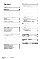
software 8 About firmware updates 8 About the Owner's Manual 8 Conventions in this manual 8 An overview of the QL series 9 Features 9 About the models 10 Controls and functions 11 Top panel 11 Front panel 15 Rear panel 16 (Calibration function 46 Troubleshooting 48 Attaching the RK1 - Yamaha QL5 | Owner's Manual - Page 3
of important operating and maintenance (servicing) instructions in the literature accompanying the sold with the apparatus. When a cart is used, use caution when moving the cart/apparatus combination to le chariot, le stand, le trépied, le support ou la table recommandés par le fabricant ou vendus - Yamaha QL5 | Owner's Manual - Page 4
uses radio frequencies and, if not installed and used according to the instructions found in the users manual problem by using Yamaha Corporation of America Address: 6600 Orangethorpe Ave., Buena Park, Calif. 90620 Telephone: 714-522-9011 Type of Equipment: Digital Mixing Console Model Name: QL5/QL1 - Yamaha QL5 | Owner's Manual - Page 5
, discontinue use immediately and have it inspected by qualified Yamaha service personnel. Water warning • Do not expose the device to rain, use it near , make sure that the AC outlet you are using is easily accessible. If some trouble or malfunction occurs, immediately turn off the power switch - Yamaha QL5 | Owner's Manual - Page 6
and/or damage to the device(s). If the backup battery power is fully depleted, have qualified Yamaha service personnel replace the battery. Yamaha cannot be held responsible for damage caused by improper use or modifications to the device, or data that is lost or destroyed. PA_en_2 2/2 6 Owner - Yamaha QL5 | Owner's Manual - Page 7
clock data will be reset. Replace the backup battery before it becomes fully depleted. When the backup battery is running low, the LCD display indicates "Low Battery" when you start up the system. In this case, contact your Yamaha dealer and have qualified Yamaha service personnel replace the backup - Yamaha QL5 | Owner's Manual - Page 8
of trouble-free use, please read this owner's manual carefully before operating your console. After you have read the manual, keep it in a safe place. Accessories • AC power cord • Owner's Manual (this document) • Dante Virtual Soundcard license code • Dust cover (QL5 only) About utility software QL - Yamaha QL5 | Owner's Manual - Page 9
analog inputs and outputs to/from external Dante devices without passing through the mixing channels. Further, you can remotely control the head amps from other CL series and QL series consoles, allowing QL series consoles to be used as remote I/O devices. You can use recall safe in the port to port - Yamaha QL5 | Owner's Manual - Page 10
You can cascade a second QL series unit or another digital mixer, such as the Yamaha CL series, M7CL, PM5D or LS9, connected via a digital I/O card installed in a slot or a Dante connector. (Cascade connections via a Dante connector are possible only between QL series consoles.) You can cascade any - Yamaha QL5 | Owner's Manual - Page 11
2 SENDS ON FADER section page 12 3 Display section page 13 4 Selected Channel section page 13 5 USB connector page 15 6 USER DEFINED KEYS section page 14 7 FADER BANK section page 14 8 Master section page 14 NOTE This illustration shows the top panel of the QL5. 8 Owner's Manual 11 - Yamaha QL5 | Owner's Manual - Page 12
-selected MIX/MATRIX bus. 1 1 MIX/MATRIX buses [1]-[16] For selecting the MIX/MATRIX buses whose send levels will be adjusted in the Selected Channel section. The LED of the key corresponding to the currently selected bus will light (or flash, in the case of a MATRIX bus). In SENDS ON FADER mode - Yamaha QL5 | Owner's Manual - Page 13
AND TURN] knob You can press a desired knob in the touch screen and then use this knob to operate it. The LED below this knob indicates the color of amp's analog gain for an input channel. Alternately, it adjusts the digital gain if GAIN KNOB FUNCTION is set to DIGITAL GAIN in the PREFERENCE tab of - Yamaha QL5 | Owner's Manual - Page 14
the custom fader banks, refer to page 22. 14 Owner's Manual 1 [SEL] key Selects the channel you wish to control. Pressing this key will cause the channel LED to light up, and you will be able to control the channel in both the Selected Channel section and on the touch screen. If the STEREO bus - Yamaha QL5 | Owner's Manual - Page 15
channel. flash drives.) The FAT16 and FAT32 formats are supported. Prevention of accidental erasure Some USB flash contains important data, it is a good idea to use the write-protect setting to prevent accidental erasure. On or power-off the QL unit while this indicator is shown. Doing so may - Yamaha QL5 | Owner's Manual - Page 16
the Yamaha LA1L). (The QL5 includes these connectors at two locations. The QL1 includes one.) 2 OMNI OUT jacks XLR-3-32 male output jacks for outputting analog audio signals. (The QL5 has 16 of these jacks. The QL1 has 8.) These jacks are used mainly to output the signals of MIX channels or MATRIX - Yamaha QL5 | Owner's Manual - Page 17
jack that outputs the digital audio signal of a desired channel in AES/EBU format. This is used mainly to output the signal of the STEREO/MONO channel. B SLOT 1-2 light when the Dante network is functioning as Giga-bit Ethernet. F NETWORK connector This RJ-45 connector allows the QL unit to be - Yamaha QL5 | Owner's Manual - Page 18
the basic procedures you can perform on the QL's touch screen. Pressing the touch screen You will mainly use this operation to switch screens and pages, from a list, such as a list of USER DEFINED keys. For the channel select buttons, you can select multiple buttons by moving your finger across the - Yamaha QL5 | Owner's Manual - Page 19
to a scene or library, or when you need to assign a channel name. Press characters in the window to enter the desired characters. On show several buttons called "tool buttons" at the top of the window. You can use these tool buttons to recall or copy/paste library data. Press the "X" (close) - Yamaha QL5 | Owner's Manual - Page 20
Dante QL series console from a USB flash drive. 5 SENDS ON FADER Press this button to switch to SENDS ON FADER mode, where you can use Channel Job) Press this button to display the CH JOB menu, which you can make settings for channel . 9 RACK When you press this button, the VIRTUAL RACK screen will - Yamaha QL5 | Owner's Manual - Page 21
/dynamics) or rack (GEQ/effect/premium rack). 5 COMPARE button This button exchanges the settings copied to buffer memory with the settings of the currently selected channel (EQ/dynamics) or rack (GEQ/effect/premium rack). For some windows, a variety of tool buttons also appear. Owner's Manual 21 - Yamaha QL5 | Owner's Manual - Page 22
. The CUSTOM FADER BANK/MASTER FADER page will appear. 4. Select the custom fader bank you want to set. The channel strip is divided into 1-16, 17-24 (QL5 only), and Master, from the left side of the console. 5. Press the Fader select button you want to set, then press the [SEL] key for the - Yamaha QL5 | Owner's Manual - Page 23
channel to the currently selected MIX/MATRIX bus. NOTE • If the function for switching between MIX 1-16 channel being operated, and use the fader to adjust the send level to the selected MIX/MATRIX bus. Assigning a name On the QL series, you can assign a name to each input channel, output channel - Yamaha QL5 | Owner's Manual - Page 24
character, the newly entered character will overwrite the selected region. Using libraries You can use libraries to store (save) or recall (load) the settings of the currently selected channel (EQ/dynamics) or rack (GEQ/effect/premium rack). The method of operation is essentially the same for each - Yamaha QL5 | Owner's Manual - Page 25
button in the function access area, press a rack container in which a GEQ/effect/Premium Rack is already mounted. 1 2 1 RACK button 2 RACK container [HPF/EQ window (8ch)] [DYNAMICS 1/2 window (8ch)] In addition to using the panel [SEL] keys or the channel select button in the function access area - Yamaha QL5 | Owner's Manual - Page 26
Basic operation of the QL series [VIRTUAL RACK screen] Use the rack select tabs at the bottom of the window to select a rack. NOTE You cannot select a rack select tab of a rack in which no GEQ, effect, or Premium Rack is mounted. 3. Press the LIBRARY button. The screen for the selected library - Yamaha QL5 | Owner's Manual - Page 27
. NOTE You can select only one channel or rack as the source for storing. If multiple channels are selected in the dynamics or EQ window, you will not be able to perform the Store operation. 3. Press the LIBRARY button. The screen for the selected library appears. Using libraries • Be aware that if - Yamaha QL5 | Owner's Manual - Page 28
effects/GEQ mounted in a rack • Between the same processors mounted in a premium rack NOTE Only 31BandGEQ settings that use less than channel or rack. NOTE If you're pasting EQ/dynamics settings, you can use the 8ch/ALL window to select multiple channels as the paste-destination. In this case - Yamaha QL5 | Owner's Manual - Page 29
Comparing two sets of settings You can use the COMPARE button to switch between the settings copied to the buffer memory and the settings of the currently selected channel (EQ/dynamics) or rack (GEQ/effect/premium rack). This is convenient when you want to copy an interim result of your editing, and - Yamaha QL5 | Owner's Manual - Page 30
• It transmits up to 512 in/512 out, for a total 1024 channels (in theory) of audio over a GbE network. (The QL series features QL5: 64 in/64 out, QL1: 32 in/32 out with a 24/32-bit resolution.) • Dante-enabled devices will automatically configure their network interfaces and find each other on the - Yamaha QL5 | Owner's Manual - Page 31
QL series consoles and I/O devices Use the Dante connectors on the QL series console and I/O devices to connect them as follows. Network Switch PRIMARY EF012 EF012 EF 01 EF 01 QL5 affecting the audio even if an unexpected network problem should occur. About redundant networks A redundant network - Yamaha QL5 | Owner's Manual - Page 32
Audio input/output connections Analog input connections INPUT jacks on the console and I/O devices are used mainly to connect microphones or monaural line-level devices. QL series Analog output connections To the OMNI OUT jacks on the QL series and the OUTPUT jacks on I/O devices, you can patch the - Yamaha QL5 | Owner's Manual - Page 33
12 13 14 15 16 17 18 19 20 21 22 FOH (QL) Digital input/output connections Use the DIGITAL OUT jack to send the QL's internal signals to an external digital audio device. When the QL is in the default state, the output signal of the STEREO channel is patched to the DIGITAL OUT jack, which enables - Yamaha QL5 | Owner's Manual - Page 34
this order: 1) the I/O device, 2) the QL series, and 3) the amplifier. 4. Press the SETUP button, DANTE SETUP button, and DEVICE MOUNT tab in the touch screen. 5. Mount the I/O device. 3. Press the SETUP tab in the lower part of the DANTE SETUP screen. 4. Set CONSOLE ID to #1, and SECONDARY PORT - Yamaha QL5 | Owner's Manual - Page 35
DANTE PATCH tab in the upper part of the I/O DEVICE screen. 3. Press the DANTE INPUT PATCH button in the I/O DEVICE screen. Setting the input channels Setting the input channels , select the output channels you want to output to the rack. 5. Press the setting all digital mixing console output - Yamaha QL5 | Owner's Manual - Page 36
section, to return to the SELECTED CHANNEL VIEW screen. 3. Adjust EQ of the EQ parameter field in the Selected Channel section. 4. To make fine adjustments to EQ settings, press the EQ parameter field in the touch screen. 5. Edit the EQ type and filter type in the HPF/EQ window. 36 Owner's Manual - Yamaha QL5 | Owner's Manual - Page 37
using the faders. (For QL1, press the FADER ASSIGN field to select the region to operate.) 9. Perform the same operations for other GEQs as desired. NOTE The graphic EQ of the GEQ rack is for output channels. To use GEQ for input channels, mount a graphic EQ in the EFFECT RACK. Owner's Manual - Yamaha QL5 | Owner's Manual - Page 38
Quick Guide Using Automixer 1. Press the RACK button in the touch screen. 2. Press the GEQ tab. 3. Press the rack mount button in the VIRTUAL RACK screen. 4. Press the 8ch Automixer button in the RACK MOUNTER screen. 13. Press the rack container in which you mounted Automixer. 14. Making sure no - Yamaha QL5 | Owner's Manual - Page 39
selected in step 3 11. Press the [SEL] key for the channel used for Effect Return in the Channel Strip section. 12. Adjust the effect return level using the fader. 13. If necessary, press the RACK button, then the rack container in the EFFECT tab, and then set the effect parameters as desired - Yamaha QL5 | Owner's Manual - Page 40
Strip section, select the bank that includes the channel for the premium rack you want to use. 9. Press the [SEL] key of the channel for the premium rack you want to use. 10. Press the RACK EDIT button in the INSERT field in the SELECTED CHANNEL VIEW screen. 4. Assign OUT and IN for INSERT or - Yamaha QL5 | Owner's Manual - Page 41
ON button. 6. Press the INPUT TO TALKBACK button to select an input. Press the A.GAIN knob to enable it, then, while observing the meter, use the knob to adjust the level. 4. To assign other channels to a group, select the channel, then press DCA or MUTE group numbers in the same way. Owner - Yamaha QL5 | Owner's Manual - Page 42
Routing the oscillator to an output channel 1. Press the MONITOR button in the touch screen. Using scene memories Storing a scene 1. Press the SCENE field in the function access area. 2. Press the OSCILLATOR , and HA (Head Amp) settings will also return to their default state. 42 Owner's Manual - Yamaha QL5 | Owner's Manual - Page 43
to the USB connector of the QL unit. 2. Press the RECORDER button in the touch screen. Recording and playing audio using a USB flash drive Playing . 6. Adjust the gain using the PLAYBACK OUT GAIN knob, then in the Channel Strip section use the faders for the channels selected in the PLAYBACK OUT - Yamaha QL5 | Owner's Manual - Page 44
Guide Saving and loading the unit settings Saving the unit settings to a USB flash drive 1. Connect a USB flash drive to the USB connector of the QL file. Formatting a USB flash drive on the QL unit 1. Connect a USB flash drive (that you want to format) to the QL unit. 2. In the SAVE/LOAD screen, - Yamaha QL5 | Owner's Manual - Page 45
lets you adjust the brightness of the touch screen, top panel LEDs, channel name displays, and lamps connected to the rear panel LAMP connectors. built into the QL unit, and how to select a date and time display format. The date and time you specify here are used for the time stamp used when saving - Yamaha QL5 | Owner's Manual - Page 46
Manual. 1. Press and hold the [SEL] key for Fader B in the Master section on the panel while turning the power on. After the opening screen, the startup menu screen will appear. This window will also appear if a problem is detected in the fader settings while the QL except DANTE SETUP The console will - Yamaha QL5 | Owner's Manual - Page 47
If the RESTART button appears, calibration has failed. Press the RESTART button to execute calibration once again. 10. Press the EXIT button. The console will start up in normal operating mode. NOTE Alternatively, you can continue operation by selecting a different menu instead of pressing the EXIT - Yamaha QL5 | Owner's Manual - Page 48
Troubleshooting Troubleshooting A FAQ section is available on the Yamaha Pro Audio site. http://www.yamahaproaudio.com/ Power does not turn on; panel LEDs and the LCD display do not light. Is the QL digital gain on the head channel raised? Try using the various screens of problem will occur - Yamaha QL5 | Owner's Manual - Page 49
correctly? Does the channel being controlled match the channel on the I/O device? Cannot control the QL unit from QL Editor. Is the QL unit connected to the WiFi access point correctly? Is the network setting on the QL unit specified cor- rectly? Refer to the QL StageMix Owner's Manual - Yamaha QL5 | Owner's Manual - Page 50
(sold separately) You can attach the optional RK-1 rackmount kit to the QL5 and QL1 and mount it in a rack or an installed system. 1. Make sure that the power is turned off power switch on the unit and use the screws that are included with the RK1. Otherwise, malfunctions or electric shock may - Yamaha QL5 | Owner's Manual - Page 51
Accessories Owner's Manual, dust cover (QL5 only), power cord Optional Accessories Rackmount kit RK1, Mini-YGDAI cards*2, Gooseneck Lamp LA1L *1. A 22kHz, 30dB/Oct filter is used to measure crosstalk. *2. For more information about Mini-YGDAI card support, refer to the Yamaha pro audio website - Yamaha QL5 | Owner's Manual - Page 52
Dimensional Diagrams Dimensional Diagrams QL5 19 272 563 QL1 19 828.4 468 52 Owner's Manual 272 Units: mm 562 - Yamaha QL5 | Owner's Manual - Page 53
Dante Controller 30 Analog gain 35 Automixer 38 B Buttons 19 C Calibrating the faders 46 Channel link 41 Copy/Paste (library 28 Custom fader bank 22 D Dante Patch 40 PREMIUM RACK 9, 39 R Rear panel 16 Recorder 43 Redundant network 31 S Scene memory 42 Selected Channel section 13 SENDS - Yamaha QL5 | Owner's Manual - Page 54
- Yamaha QL5 | Owner's Manual - Page 55
OUT L METER RACK OUT R EFFECT CUE PREMIUM RACK2-8 (same as PREMIUM RACK1) INPUT PATCH DANTE IN 1-64{32} INPUT 1-32{16} SLOT1 1-16 SLOT2 1-16 PLAYBACK OUT L/R FX1-8 OUT A(L)/B(R) PR1-2 OUT A(L)/B(R) TALKBACK DANTE IN 1-64{32} INPUT 1-32{16} INPUT SELECT SLOT1 1-16 SLOT2 1-16 DANTE IN 1-64{32 - Yamaha QL5 | Owner's Manual - Page 56
30 31 -160 -190 32 -170 -200 33 34 -180 -210 35 36 -190 Analog GAIN Digital Φ AD Max. Input [+30dBu] Nominal Input [+10dBu] Max. Input [-42dBu] Nominal Input [-62dBu] INPUT 1-32{16} (GAIN MIN.) INPUT 1-32{16} (GAIN MAX.) EQ DYN DYN LEVEL INSERT ATT. (x4) 1 2 INSERT DELAY DCA /ON PAN BUS - Yamaha QL5 | Owner's Manual - Page 57
430-8650 Tel: +81-53-460-2312 OCEANIA AUSTRALIA Yamaha Music Australia Pty. Ltd. Level 1, 99 Queensbridge Street, Southbank, Victoria 3006, Australia Tel: 3-9693-5111 COUNTRIES AND TRUST TERRITORIES IN PACIFIC OCEAN Yamaha Corporation Sales & Marketing Division Nakazawa-cho 10-1, Naka-ku, Hamamatsu - Yamaha QL5 | Owner's Manual - Page 58
Yamaha Pro Audio Global Web Site http://www.yamahaproaudio.com/ Yamaha Manual Library http://www.yamaha.co.jp/manual/ C.S.G., PA Development Division © 2014 Yamaha Corporation 402MATO-A0 Printed in Japan ZH99130
-
 1
1 -
 2
2 -
 3
3 -
 4
4 -
 5
5 -
 6
6 -
 7
7 -
8
-
9
-
10
-
11
-
12
-
13
-
14
-
15
-
16
-
17
-
18
-
19
-
20
-
21
-
22
-
23
-
24
-
25
-
26
-
27
-
28
-
29
-
30
-
31
-
32
-
33
-
34
-
35
-
36
-
37
-
38
-
39
-
40
-
41
-
42
-
43
-
44
-
45
-
46
-
47
-
48
-
49
-
50
-
51
-
52
-
53
-
54
-
55
-
56
-
57
-
58
 |
 |

EN
Owner’s Manual
Keep This Manual For Future Reference.