Yamaha QY700 Owner's Manual - Page 243
Data display, Variation mode, Reverb type, Reverb return, Reverb pan, Chorus Type, Chorus return,
 |
View all Yamaha QY700 manuals
Add to My Manuals
Save this manual to your list of manuals |
Page 243 highlights
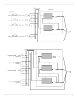
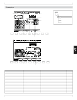
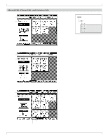
4. Pattern Effects • The Effect Connection Setup page selects the variation mode, and the pan and transmission levels for each of the three effects (variation, chorus, and reverb). You can also use it to set the effect types themselves, although these settings are also accessible from the corresponding edit pages (→ p.244). 1. At the PATCH screen, press 3 (Effect). w The QY700 enters the Pattern Effects submode. 2. If necessary, press 1 (Connect) to move to the Effect Connection Setup screen. 3. Move the cursor to the parameters that you need to set, and change the values using the data dial, n/ y, or the numeric keypad. 4. When you are ready to return to the PATCH screen, press e. • The playback keys (p, s, t, r/f) continue to function while you are adjusting the settings, so that you can monitor the results of your changes as you make them. 1. Data display • The data-display area shows the name and value of the currently selected parameter. 2. Variation mode • This setting determines whether the variation effect is handled as an insertion effect or as a system effect. (See the illustrations on page 240.) • If you set this value to Insertion, then you can apply the variation effect to no more than a single part. In this case, you can also use an assignable controller to control one of the parameters for the effect in real time. • If you set the value to System, then the variation effect operates in the same way as the chorus and reverb effects - so that you can apply it to all parts, and set values for the send and return levels. But in this case you can not use a controller to control the effect. 0101 1101 Insertion, System • Insertion: Variation effect is handled as an insertion ef- fect. • System: Variation effect is handled as a system effect. 3. Reverb type • This parameter selects the reverb effect type. 0101 1101 NO EFFECT, HALL 1, HALL 2, ROOM 1, ROOM 2, ROOM 3, STAGE 1, STAGE 2, PLATE, WHITE ROOM, TUNNEL, BASEMENT 4. Reverb return • This parameter sets the signal level returned from the reverb block. You use this setting to adjust the reverb level for all parts at the same time. 0101 1101 000,...,127 5. Reverb pan • This parameter sets the stereo positioning of the signal from the reverb block. 0101 1101 Left=63,...,Center,...,Right=63 6. Chorus Type • This parameter selects the chorus effect type. 0101 1101 NO EFFECT, CHORUS 1, CHORUS 2, CHORUS 3, CHO- RUS 4, CELESTE 1, CELESTE 2, CELESTE 3, CELESTE 4, FLANGER 1, FLANGER 2, FLANGER 3 7. Chorus return • This parameter sets the signal level returned from the chorus block. You use this setting to adjust the chorus level for all parts at the same time. 0101 1101 000,...,127 8. Chorus pan • This parameter sets the stereo positioning of the signal from the chorus block. 0101 1101 Left=63,...,Center,...,Right=63 242 Chapter 5. PATTERN MODE
-
 1
1 -
2
-
3
-
4
-
5
-
6
-
7
-
8
-
9
-
10
-
11
-
12
-
13
-
14
-
15
-
16
-
17
-
18
-
19
-
20
-
21
-
22
-
23
-
24
-
25
-
26
-
27
-
28
-
29
-
30
-
31
-
32
-
33
-
34
-
35
-
36
-
37
-
38
-
39
-
40
-
41
-
42
-
43
-
44
-
45
-
46
-
47
-
48
-
49
-
50
-
51
-
52
-
53
-
54
-
55
-
56
-
57
-
58
-
59
-
60
-
61
-
62
-
63
-
64
-
65
-
66
-
67
-
68
-
69
-
70
-
71
-
72
-
73
-
74
-
75
-
76
-
77
-
78
-
79
-
80
-
81
-
82
-
83
-
84
-
85
-
86
-
87
-
88
-
89
-
90
-
91
-
92
-
93
-
94
-
95
-
96
-
97
-
98
-
99
-
100
-
101
-
102
-
103
-
104
-
105
-
106
-
107
-
108
-
109
-
110
-
111
-
112
-
113
-
114
-
115
-
116
-
117
-
118
-
119
-
120
-
121
-
122
-
123
-
124
-
125
-
126
-
127
-
128
-
129
-
130
-
131
-
132
-
133
-
134
-
135
-
136
-
137
-
138
-
139
-
140
-
141
-
142
-
143
-
144
-
145
-
146
-
147
-
148
-
149
-
150
-
151
-
152
-
153
-
154
-
155
-
156
-
157
-
158
-
159
-
160
-
161
-
162
-
163
-
164
-
165
-
166
-
167
-
168
-
169
-
170
-
171
-
172
-
173
-
174
-
175
-
176
-
177
-
178
-
179
-
180
-
181
-
182
-
183
-
184
-
185
-
186
-
187
-
188
-
189
-
190
-
191
-
192
-
193
-
194
-
195
-
196
-
197
-
198
-
199
-
200
-
201
-
202
-
203
-
204
-
205
-
206
-
207
-
208
-
209
-
210
-
211
-
212
-
213
-
214
-
215
-
216
-
217
-
218
-
219
-
220
-
221
-
222
-
223
-
224
-
225
-
226
-
227
-
228
-
229
-
230
-
231
-
232
-
233
-
234
-
235
-
236
-
237
-
 238
238 -
 239
239 -
 240
240 -
 241
241 -
 242
242 -
 243
243 -
 244
244 -
 245
245 -
 246
246 -
 247
247 -
 248
248 -
249
-
250
-
251
-
252
-
253
-
254
-
255
-
256
-
257
-
258
-
259
-
260
-
261
-
262
-
263
-
264
-
265
-
266
-
267
-
268
-
269
-
270
-
271
-
272
-
273
-
274
-
275
-
276
-
277
-
278
-
279
-
280
-
281
-
282
-
283
-
284
-
285
-
286
-
287
-
288
-
289
-
290
-
291
-
292
-
293
-
294
-
295
-
296
-
297
-
298
-
299
-
300
-
301
-
302
-
303
-
304
-
305
-
306
-
307
-
308
-
309
-
310
-
311
-
312
-
313
-
314
-
315
-
316
-
317
-
318
-
319
-
320
-
321
-
322
-
323
-
324
-
325
-
326
-
327
-
328
-
329
-
330
-
331
-
332
-
333
-
334
 |
 |