Yamaha RX-V473 Owners Manual - Page 26
Connecting to the jacks on the front panel, Connecting the FM/AM antennas - scene
 |
View all Yamaha RX-V473 manuals
Add to My Manuals
Save this manual to your list of manuals |
Page 26 highlights
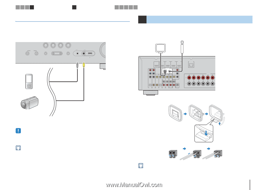
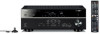
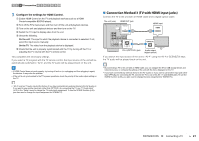
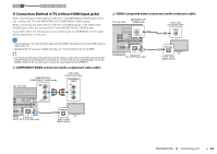
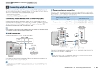
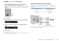
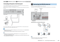
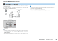
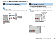
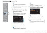
1 2 3 4 Playback device connections 5 FM/AM antenna connections 6 7 8 9 10 Connecting to the jacks on the front panel Use the VIDEO AUX jacks on the front panel to temporarily connect devices such as camcorders and portable audio players to the unit. Before making a connection, stop playback on the device and turn down the volume on the unit. BD DVD SCENE TV NET RADIO INPUT TONE CONTROL PROGRAM STRAIGHT VIDEO AUX USB AUDIO VIDEO iPod/iPhone/iPad 5V 2.1A The unit (front) V Portable audio player 5 Connecting the FM/AM antennas Connect the supplied FM/AM antennas to the unit. Fix the end of the FM antenna to a wall, and place the AM antenna on a flat surface. AM antenna FM antenna The unit (rear) HDMI OUT ARC HDMI 1 (BD/DVD) HDMI 2 HDMI 3 HDMI 4 PR PB Y COMPONENT VIDEO VIDEO ANTENNA AM FM COMPONENT VIDEO PR PB Y MONITOR OUT OPTICAL AV 1 COAXIAL AV 2 COAXIAL AV 3 OPTICAL ( TV ) AV 4 AV 5 AV 6 AV OUT SUBWOOFER AUDIO NETWORK FRONT CENTER SPEAKERS SURROUND BA /ZONE SURROUND Assembling and connecting the AM antenna Camcorder If you select "V-AUX" as the input source by pressing V-AUX, the video/audio played back on the device will be output from the unit. • To watch videos input to the VIDEO AUX (VIDEO) jack, you need to connect your TV to the MONITOR OUT (VIDEO) jack of the unit (p.22). • You need to prepare the video/audio cables that match the output jacks on your device. • For details on how to connect an iPod or a USB storage device, see "Connecting an iPod" (p.46) or "Connecting a USB storage device" (p.50). • When "USB" is selected as the input source, video signals input to the VIDEO AUX (VIDEO) jack are output from the MONITOR OUT (VIDEO) jack. Hold down Insert Release • Unwind only the length of cable needed from the AM antenna unit. • The wires of the AM antenna have no polarity. PREPARATIONS ➤ Connecting the FM/AM antennas En 26
-
 1
1 -
2
-
3
-
4
-
5
-
6
-
7
-
8
-
9
-
10
-
11
-
12
-
13
-
14
-
15
-
16
-
17
-
18
-
19
-
20
-
 21
21 -
 22
22 -
 23
23 -
 24
24 -
 25
25 -
 26
26 -
 27
27 -
 28
28 -
 29
29 -
 30
30 -
 31
31 -
32
-
33
-
34
-
35
-
36
-
37
-
38
-
39
-
40
-
41
-
42
-
43
-
44
-
45
-
46
-
47
-
48
-
49
-
50
-
51
-
52
-
53
-
54
-
55
-
56
-
57
-
58
-
59
-
60
-
61
-
62
-
63
-
64
-
65
-
66
-
67
-
68
-
69
-
70
-
71
-
72
-
73
-
74
-
75
-
76
-
77
-
78
-
79
-
80
-
81
-
82
-
83
-
84
-
85
-
86
-
87
-
88
-
89
-
90
-
91
-
92
-
93
-
94
-
95
-
96
-
97
-
98
-
99
-
100
-
101
-
102
-
103
-
104
-
105
-
106
-
107
-
108
-
109
-
110
-
111
-
112
-
113
-
114
-
115
-
116
-
117
-
118
-
119
-
120
-
121
-
122
-
123
-
124
-
125
-
126
-
127
-
128
-
129
-
130
-
131
-
132
-
133
 |
 |