Yamaha RX-V473 Owners Manual - Page 28
Connecting recording devices, Connecting the power cable - component to hdmi
 |
View all Yamaha RX-V473 manuals
Add to My Manuals
Save this manual to your list of manuals |
Page 28 highlights
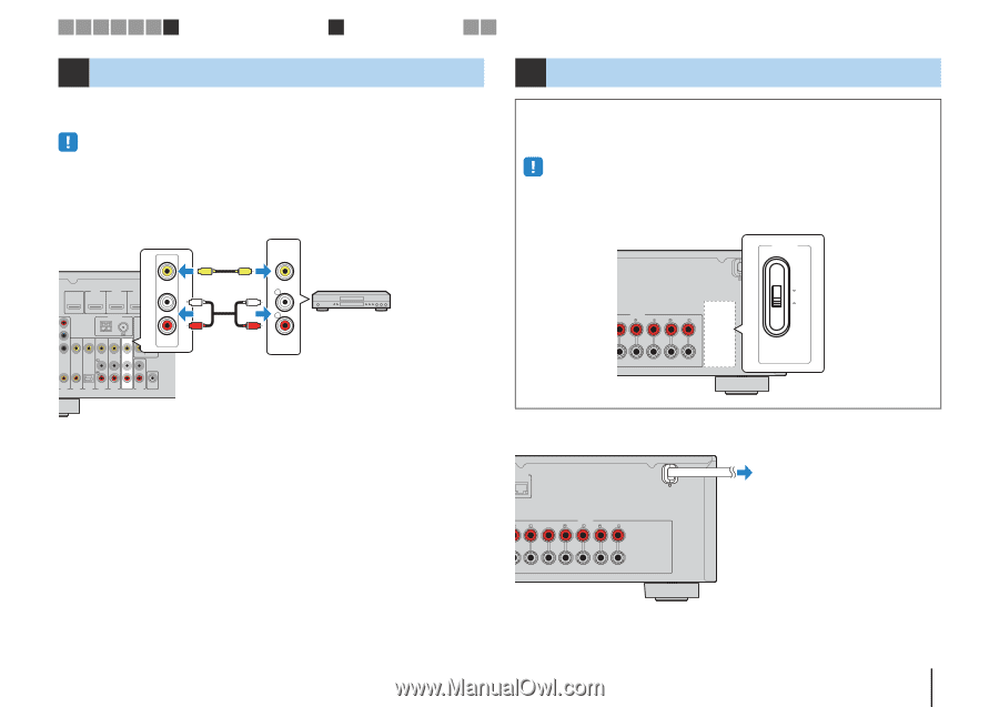
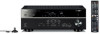
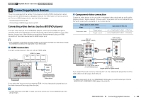
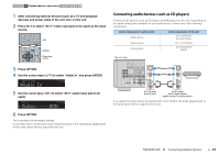
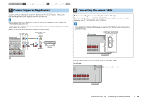
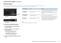
1 2 3 4 5 6 7 Recording device connections 8 Power cable connection 9 10 7 Connecting recording devices You can connect video/audio recording devices to the AV OUT jacks. These jacks output analog video/audio signals selected as the input. • To copy video/audio from a video device, connect the video device to the AV 5-6 jacks or VIDEO AUX (VIDEO/AUDIO) jacks of the unit. • To copy audio from an audio device, connect the audio device to the AV 5-6 jacks, AUDIO jacks, or VIDEO AUX (AUDIO) jacks of the unit. • Be sure to use the AV OUT jacks only for connecting recording devices. AV OUT jacks The unit (rear) V Video/audio input VIDEO V HDMI OUT HDMI 1 (BD/DVD) HDMI 2 HDMI 3 HDMI 4 ARC L VIDEO ANTENNA AM FM COMPONENT VIDEO PR R PB Y MONITOR OUT AV OUT L L R R AUDIO Video recording device COAXIAL AV 2 COAXIAL AV 3 OPTICAL ( TV ) AV 4 AV 5 AV 6 AV OUT SUBWOOFER AUDIO 8 Connecting the power cable Before connecting the power cable (General model only) Set the switch position of VOLTAGE SELECTOR according to your local voltage. Voltages are AC 110-120/220-240 V, 50/60 Hz. • Make sure you set VOLTAGE SELECTOR of the unit BEFORE plugging the power cable into an AC wall outlet. Improper setting of VOLTAGE SELECTOR may cause damage to the unit and create a potential fire hazard. The unit (rear) VOLTAGE SELECTOR VOLTAGE SELECTOR ENTER SPEAKERS SURROUND SURROUND BACK/BI AMP /ZONE B SINGLE 110V 120V 220V 240V After all the connections are complete, plug in the power cable. The unit (rear) NETWORK To an AC wall outlet FRONT CENTER SPEAKERS SURROUND SURROUND BACK/BI AMP /ZONE B SINGLE PREPARATIONS ➤ Connecting recording devices En 28
-
 1
1 -
2
-
3
-
4
-
5
-
6
-
7
-
8
-
9
-
10
-
11
-
12
-
13
-
14
-
15
-
16
-
17
-
18
-
19
-
20
-
21
-
22
-
 23
23 -
 24
24 -
 25
25 -
 26
26 -
 27
27 -
 28
28 -
 29
29 -
 30
30 -
 31
31 -
 32
32 -
 33
33 -
34
-
35
-
36
-
37
-
38
-
39
-
40
-
41
-
42
-
43
-
44
-
45
-
46
-
47
-
48
-
49
-
50
-
51
-
52
-
53
-
54
-
55
-
56
-
57
-
58
-
59
-
60
-
61
-
62
-
63
-
64
-
65
-
66
-
67
-
68
-
69
-
70
-
71
-
72
-
73
-
74
-
75
-
76
-
77
-
78
-
79
-
80
-
81
-
82
-
83
-
84
-
85
-
86
-
87
-
88
-
89
-
90
-
91
-
92
-
93
-
94
-
95
-
96
-
97
-
98
-
99
-
100
-
101
-
102
-
103
-
104
-
105
-
106
-
107
-
108
-
109
-
110
-
111
-
112
-
113
-
114
-
115
-
116
-
117
-
118
-
119
-
120
-
121
-
122
-
123
-
124
-
125
-
126
-
127
-
128
-
129
-
130
-
131
-
132
-
133
 |
 |