Yamaha VAF2-3115 Owner's Manual
Yamaha VAF2-3115 Manual
 |
View all Yamaha VAF2-3115 manuals
Add to My Manuals
Save this manual to your list of manuals |
Yamaha VAF2-3115 manual content summary:
- Yamaha VAF2-3115 | Owner's Manual - Page 1
EN ARRAY FRAME VAF2-3115(W) Owner's Manual Thank you for choosing this Yamaha product. Please read this manual carefully before using it in a speaker installation. Keep the manual in safe place for future reference. Package Contents VAF2-3115(W) ❒ 3-1186 Angle indicator plate (2 pcs.) ❒ 3-1189
-
 1
1
 |
 |
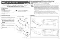
Angle Indicator Plate
(3-1186)[2X]
Rear Joiner Plate
(3-1189)[2X]
M10 EyeBolt
[Rear Pull Back]
M10 Flat Washer
[TYP]
M10 Screw
[TYP]
60
°
Maximun Splay Configuration
Tight Pack Configuration
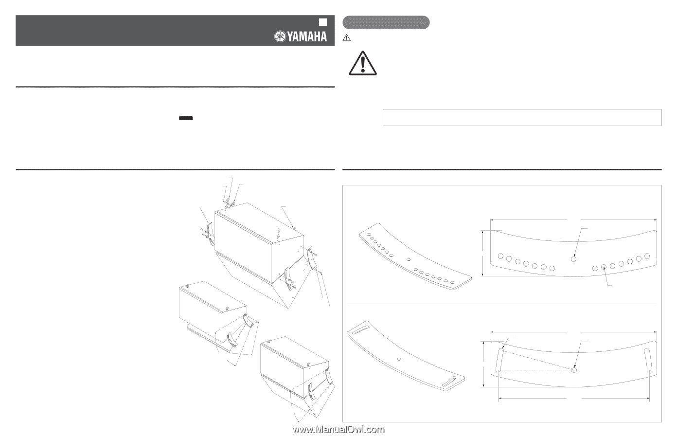
3-1186
Angle Indicator Plate
3-1189
Rear Joiner Plate
1/2-13 TAPPED HOLE
.402 DIA. X 15
°
SLOT
2X
1/2-13 TAPPED HOLE
φ
.402 14X
14.500
14.500
13.170
4.00
4.00
30
°
60
°
M10 Screw [TYP]
M10 EyeBolt [2X]
Thank you for choosing this Yamaha product.
Please read this manual carefully before using it in a speaker installation.
Keep the manual in safe place for future reference.
Installation Instructions
1.
Determine the splay of the speakers and the holes to use for
the splay angle. Remove the speaker screws.
2.
Set the speakers so the top are facing up. Attach a rear
joiner plate on the top rear insert of the speaker using the
slots of the plates with the provided screws and washers.
Attach another angle indicator plate on the top front insert
using t the corresponding holes for the appropriate splay
angle with the provided screws and washers. Tighten
permanently.
3.
Carefully flip the speakers up side down so the bottoms are
facing up.
4.
Repeat step 2 for installing the other angle indicator plate
and rear joiner plate.
5.
Flip the speaker on its side and install two M10 eye bolts on
the side of the speaker.
6.
Use the eye bolts to suspend the speaker cluster assembly.
Dimensions
• Use only the eye bolts included with the speaker unit.
• For information on load limits and the strength of the eyebolt,
refer to the owner's manual of the speaker.
Package Contents
VAF2-3115(W)
❒
3-1186
Angle indicator plate (2 pcs.)
❒
3-1189
Rear Joiner plate (2 pcs.)
❒
3-0235
M10-40mm button head socket screws (8 pcs.)
❒
2-1432
M10 flat washers (11 pcs.)
❒
3-0112
M10 L-key wrench (1 pc.)
NOTE
VAF2-3115(W)
ARRAY FRAME
Owner’s Manual
EN
PRECAUTIONS
Always follow the basic precautions listed below to avoid the possibility of physical injury to you or others, or damage to the device
or other property. These precautions include, but are not limited to, the following:
• Before doing any installation or construction work, consult with an installation expert.
• Make sure that the surface this bracket is being mounted on has the strength to handle the weight of both the speaker and this
bracket.
• Use bolts and nuts as well as washers for installation and tighten them firmly so that the speaker is secure and does not move.
• Always loosen the corresponding screw before adjusting the angle or direction of the speaker. Never force this adjustment with
the screw still tightened.
• Some fittings may deteriorate over extended periods of time due to wear and/or corrosion. For optimum safety, the installation
should be checked thoroughly at regular intervals.
Yamaha cannot be held responsible for damage or injury caused by insufficient strength of the support structure or
improper installation.
* Illustrations herein are for explanatory purposes only, and may not match actual appearance during operation.
* Company names and product names herein are trademarks or registered trademarks of their respective companies.
* Specifications and descriptions in this owner's manual are for information purposes only. Yamaha Corp. reserves the right to
change
or modify products or specifications at any time without prior notice. Since specifications, equipment or options may
not be the same in every locale, please check with your Yamaha dealer.
CAUTION
PLEASE READ CAREFULLY BEFORE PROCEEDING
* Please keep this manual in a safe place for future reference.