Yamaha YG4000DC Owners Manual
Yamaha YG4000DC - Gasoline Generator Manual
 |
View all Yamaha YG4000DC manuals
Add to My Manuals
Save this manual to your list of manuals |
Yamaha YG4000DC manual content summary:
- Yamaha YG4000DC | Owners Manual - Page 1
OWNER'S MANUAL Generator LIT-19626-01-15 EF4000DE EF5200DE EF6600DE YG4000D YG5200D YG6600D YG6600DE 7WV-28199-11 - Yamaha YG4000DC | Owners Manual - Page 2
- Yamaha YG4000DC | Owners Manual - Page 3
number. Keep a record of these numbers for reference 790-060 when ordering parts from a Yamaha dealer. AE00022 EF4000DE/EF5200DE/EF6600DE YG4000D/YG5200D/YG6600D/YG6600DE OWNER'S MANUAL © 2003 by Yamaha Motor Corporation, U.S.A. 1st Edition, August 2003 All rights reserved. Any reprinting or - Yamaha YG4000DC | Owners Manual - Page 4
time of printing, there may be minor discrepancies between your engine and this manual. If there is any question concerning this manual, please consult a Yamaha dealer. 9 This manual should be considered a permanent part of this engine and should remain with this engine when resold. Particularly - Yamaha YG4000DC | Owners Manual - Page 5
CHART 25 SPARK PLUG INSPECTION............27 CARBURETOR ADJUSTMENT .......27 ENGINE OIL REPLACEMENT .........28 AIR FILTER 29 FUEL COCK 30 FUEL TANK FILTER 30 MUFFLER SCREEN AND SPARK ARRESTER 31 BATTERY 34 FUSE REPLACEMENT 35 G.F.C.I. RECEPTACLE TEST ..........35 TROUBLESHOOTING 36 STORAGE - Yamaha YG4000DC | Owners Manual - Page 6
warranty shall include parts replaced due to normal wear or routine maintenance. THE CUSTOMER'S RESPONSIBILITY under this warranty shall be to: 1. Operate and maintain the generator as speci- fied in the appropriate Owner's Manual; 2. Give notice to an authorized Yamaha consumer generator dealer of - Yamaha YG4000DC | Owners Manual - Page 7
shall include parts replaced due to normal wear or routine maintenance. THE CUSTOMER'S RESPONSIBILITY under this warranty shall be to: 1. Operate and maintain the diesel generator as specified in the appropriate Owner's Manual; 2. Give notice to an authorized Yamaha industrial generator dealer of - Yamaha YG4000DC | Owners Manual - Page 8
A. Yes, if you are a qualified mechanic and follow the procedures specified in the Owner's and Service Manual. We do recommend, however, that items requiring special tools or equipment be done by a Yamaha generator dealer. Q. Will the warranty be void or cancelled if I do not operate or maintain my - Yamaha YG4000DC | Owners Manual - Page 9
YG4000D) Please read the following labels carefully before operating this machine. NOTE: Maintain or replace safety and instruction labels, as necessary. tw y r q 1 2 WARNING Electrocution Or property damage can occur: Do not connect this generator :CATEGORY A (EPA) YAMAHA MOTOR CO. LTD zzz-2179R - Yamaha YG4000DC | Owners Manual - Page 10
generator to any building 's electrical system unless an isolation switch has been installed by a licensed electrician. Refer to the owner's manual CATEGORY A (EPA) YAMAHA MOTOR CO. LTD zzz- AIR INDEX ( C a l i f o r n i a only) 0 2 4 6 8 10 MOST CLEAN LEAST CLEAN NOTE : THE LOWER THE AIR - Yamaha YG4000DC | Owners Manual - Page 11
741-005 change your clothes. 9 When operating or transporting the machine, be sure it is kept upright. If it tilts, fuel may leak from the carburetor or fuel tank. 741-004 AE00843 ENGINE AND MUFFLER MAY BE HOT 9 Place the machine in a place where pedestrians or children are not likely to - Yamaha YG4000DC | Owners Manual - Page 12
or other equipment, or the engine may overheat. a 1 m (3 ft) 741-008a 9 Avoid operating the engine with a dust cover. q A q 741-009 9 Be sure to carry the generator only by its carrying handle(s). 1 Carrying handle(s) (shaded) 741-060 AE00083 ELECTRIC SHOCK PREVENTION 9 Never operate the engine - Yamaha YG4000DC | Owners Manual - Page 13
1.2mm (0.05 in) 741-065 å EF4000DE/YG4000D B EF5200DE/EF6600DE/YG5200D/YG6600D/YG6600DE AE00088 CONNECTION NOTES 9 Avoid connecting the generator to commercial power outlet. 9 Avoid connecting the generator in parallel with any other generator. 1 Correct 2 Incorrect AE00091 CONNECTION w Before - Yamaha YG4000DC | Owners Manual - Page 14
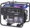
AE00102 DESCRIPTION (for EF4000DE/EF5200DE/EF6600DE) 1 Fuel tank 2 Fuel tank cap 3 Fuel cock 4 Air filter cover 5 Spark plug 6 Muffler 7 Ground (Earth) terminal 8 Oil filler cap 9 Oil drain plug 0 Recoil starter q Voltage adjuster (for EF5200DE/EF6600DE) w Fuel level gauge e Carrying handles (shaded - Yamaha YG4000DC | Owners Manual - Page 15
/YG5200D/YG6600D/ YG6600DE) 1 Fuel tank 2 Fuel tank cap 3 Fuel cock 4 Air filter cover 5 Spark plug 6 Muffler 7 Choke lever (for YG4000D/YG5200D/YG6600D) 8 Ground (Earth) terminal 9 Oil filler cap 0 Oil drain plug q Recoil starter w Fuel level gauge e Carrying handles (shaded) YG5200D/YG6600D - Yamaha YG4000DC | Owners Manual - Page 16
EF4000DE yr e q w t EF5200DE re w y t EF6600DE re w y t AE00104 CONTROL BOX (for EF4000DE/ EF5200DE/EF6600DE) 1 AC switch (N.F.B.) 2 AC receptacle 3 Voltage meter 4 Oil warning light 5 Engine switch 6 Economy idle switch q q 793-067 - 11 - - Yamaha YG4000DC | Owners Manual - Page 17
yu t q q w e o YG5200D tr qw e u y YG6600D tr qw e u y YG6600DE yt r qw e u i - 12 - AE00104 CONTROL BOX (for YG4000D/ YG5200D/YG6600D/ YG6600DE) 1 AC switch (N.F.B.) 2 G.F.C.I. receptacle 3 AC receptacle 4 Voltage meter (for YG5200D/ YG6600D/YG6600DE) 5 Oil warning - Yamaha YG4000DC | Owners Manual - Page 18
"STOP" Ignition circuit is switched off. The engine will not run. 3 6 "START" Starting circuit is switched on. The starter motor starts. å EF4000DE/EF5200DE/EF6600DE ∫ YG4000D/YG5200D/YG6600D/YG6600DE cC Take your hand off the switch immediately after the engine starts. AE00920 STARTER SWITCH (for - Yamaha YG4000DC | Owners Manual - Page 19
Supplies AC 120V and 240V (EF4000DE/YG4000D) D-2 Supplies AC 120V and 240V (EF5200DE/EF6600DE/ YG5200D/YG6600D/YG6600DE) cC Reduce the load to the specified generator rated output if the AC switch (N.F.B.) turns off. If it turns off again, consult a Yamaha dealer. AE00142 ECONOMY IDLE SWITCH When - Yamaha YG4000DC | Owners Manual - Page 20
rated voltage. 779-039 NOTE: Turn the adjuster clockwise or counterclockwise to increase or decrease output voltage. q w e 779-037 AE00848 G.F.C.I. RECEPTACLE (for YG4000D during the pre-operation checks according to the maintenance instructions on page 35. 9 Remember that only receptacles - Yamaha YG4000DC | Owners Manual - Page 21
CHECK NOTE: Pre-operation checks should be made each time the generator is used. w The engine and muffler will be very hot after the engine has been run. Avoid touching the engine and muffler while they are still hot with any part of your body or clothing during inspection or repair. 741 - Yamaha YG4000DC | Owners Manual - Page 22
the fuel filter or it motor oil ∫ SAE #30 ç SAE #20 ∂ SAE 10W Engine oil quantity: EF4000DE/YG4000D: 1.0 L (0.88 lmp qt, 1.06 US qt) EF5200DE/EF6600DE/YG5200D/YG6600D/ YG6600DE: 1.1 L (0.97 lmp qt, 1.16 US qt) NOTE: Recommended engine oil classification: API Service "SE" or "SF". cC The generator - Yamaha YG4000DC | Owners Manual - Page 23
Make sure to ground (earth) the generator. Check "SAFETY INFORMATION" on page 7. å EF4000DE/YG4000D 741-061 ∫ EF5200DE/EF6600DE/YG5200D/YG6600D/ service battery leads to prevent arcing when the battery is not installed. 9 Disconnect the battery charging output lead. Then insulate the generator - Yamaha YG4000DC | Owners Manual - Page 24
AE00955 OPERATION q NOTE: The generator has been shipped without engine oil. Fill with oil or idle switch to the "OFF" position. A B 1 3 "OFF" å AC switch (N.F.B.) for EF4000DE/YG4000D q q q 120V q ∫ AC switch (N.F.B.) for EF5200DE/EF6600DE/YG5200D/ 240V YG6600D/YG6600DE 763-196b C - Yamaha YG4000DC | Owners Manual - Page 25
battery. Do not crank the engine more than 10 seconds on any one attempt. q 701-033b q Manual Starting Model: (for YG4000D/YG5200D/YG6600D) 3. Turn the choke lever to the "1" position. 1 Choke lever å YG4000D ∫ YG5200D/YG6600D NOTE: The choke is not required to start a warm engine. Turn the choke - Yamaha YG4000DC | Owners Manual - Page 26
Operating position å YG4000D ∫ YG5200D/YG6600D 701-025d AE00970 APPLICATION RANGE AC Power factor EF4000DE/YG4000D EF5200DE/YG5200D EF6600DE YG6600D itself. cC Be sure the total load is within generator rated output otherwise generator damage will occur. NOTE: Some precision equipment is - Yamaha YG4000DC | Owners Manual - Page 27
generator rated output. 9 Be sure the receptacle load current is within receptacle rated current. 761-046 A B 1. Wind the power lead 2 or 3 turns around frame. 2. Start the engine. 3. Plug into AC receptacle. 4. Make sure the voltage meter indicates the rated voltage (except for YG4000D - Yamaha YG4000DC | Owners Manual - Page 28
switch (YG4000D) ∂ Individual AC switch (YG5200D and YG6600D(E)) 120V E 763-211 240V GR YG WX 120V 779-017 q 763-129a cC Reduce the load to the specified generator rated output if an AC switch turns off. If it turns off again, consult a Yamaha dealer. NOTE: 9 The 4-blade plug receptacle can - Yamaha YG4000DC | Owners Manual - Page 29
. 9 Turn the AC switch (N.F.B.) and economy idle switch to the "OFF" position. A B 1 3 "OFF" å AC switch (N.F.B.) (for EF4000DE/YG4000D) ∫ AC switch (N.F.B.) (for EF5200DE/EF6600DE/YG5200D/ q q q 120V q 240V YG6600D/YG6600DE) 763-196b C ç Economy idle switch q 763-126b 1. Disconnect - Yamaha YG4000DC | Owners Manual - Page 30
spark arrester. Clean/ 0 replace if necessary. Check oil level 0 6. Engine Oil Replace 0 0 7. *A*ir Filter Clean. Replace if 0 necessary. Clean fuel cock 8. Fuel Filter and fuel tank filter. Replace if 0 necessary. * : It is recommended that these items be serviced by a Yamaha - Yamaha YG4000DC | Owners Manual - Page 31
necessary. 0 14. Generation Check the voltage meter indication or 0 pilot light. G.F.C.I. receptacle 15. . for YG4000D YG5200D serviced by a Yamaha dealer. ** : Related to emission control system. cC Use only Yamaha specified genuine parts for replacement. Ask an authorized Yamaha - Yamaha YG4000DC | Owners Manual - Page 32
and gap. Standard Spark Plug: BPR4ES (NGK) a Spark Plug Gap: 760-001a 0.7-0.8 mm (0.028-0.031 in) a Gap 3. Install the spark plug. Spark Plug Torque: 20 N•m (2 kgf•m, 14 lbf•ft) AE00431 CARBURETOR ADJUSTMENT The carburetor is a vital part of the engine. Adjusting should be left to a Yamaha - Yamaha YG4000DC | Owners Manual - Page 33
If damaged, replace. w q 700-067 1 Oil drain plug 2 Gasket 3 O-ring 5. Reinstall the oil drain plug. Drain Plug Torque: 30 N•m (3.0 kgf•m, 22 lbf•ft) q 700 (10W-30) or SAE 10W-30 type SE motor oil ∫ SAE #30 ç SAE #20 ∂ SAE 10W Engine oil quantity: EF4000DE/YG4000D: 1.0 L (0.88 Imp qt, 1.06 US - Yamaha YG4000DC | Owners Manual - Page 34
cover and element. 2. Wash the element in solvent and dry. 3. Oil the element and squeeze out excess oil. The element should be wet but not dripping. Recommended oil: Foam-air-filter oil or SAE #20 motor oil cC Do not wring out the element. This could cause it to tear. NOTE: For EF4000DE/YG4000D - Yamaha YG4000DC | Owners Manual - Page 35
cup. w Be sure the fuel cock cup is tightened securely. 705-065a AE00471 FUEL TANK FILTER q 1. Remove the fuel tank cap and filter. 1 Filter 2. Clean the filter with solvent. If damaged, replace. 3. Wipe the filter and insert it. w Be sure the tank cap is tightened securely. 707-043b - 30 - Yamaha YG4000DC | Owners Manual - Page 36
muffler while they are still hot with any part of your body or clothing during inspection or repair. q 1. Remove the muffler screen. 1 Muffler screen w w 711-055 2 Screw å EF4000DE ∫ YG4000D 2. Use a flathead screw driver to pry the spark arrester out from the muffler. 711-012b q 3. Remove - Yamaha YG4000DC | Owners Manual - Page 37
å EF4000DE ∫ YG4000D AE00841 MUFFLER SCREEN AND SPARK ARRESTER (For part of your body or clothing q during inspection or repair. 1. Remove the muffler protector and muffler screen. 1 Muffler protector e w 711-056 2 Muffler screen 3 Screw 2. Use a flathead screw driver to pry the spark - Yamaha YG4000DC | Owners Manual - Page 38
wire brush lightly to avoid damaging or scratching of the muffler screen and spark arrester. 5. Check the muffler screen and spark arrester. 711-050 Replace them if damaged. wq 6. Install the spark arrester. NOTE: Align the spark arrester projection with the hole in the muffler pipe. 711-029a - Yamaha YG4000DC | Owners Manual - Page 39
the battery during engine operation. 9 Avoid operating the generator with the battery removed. 762-002 w Battery electrolyte is produce explosive gases. Keep sparks, flame, cigarettes, etc. away. Ventilate when charging or using in closed space. Always cover eyes when working near batteries - Yamaha YG4000DC | Owners Manual - Page 40
If the fuse immediately blows again, consult a Yamaha dealer. AE00501 G.F.C.I. RECEPTACLE TEST (for YG4000D/YG5200D/YG6600D/YG6600DE) 1. Start the engine. 2. If the G.F.C.I. operates incorrectly, consult a Yamaha dealer. w Do not operate the generator with a faulty G.F.C.I. circuit. Electric shock - Yamaha YG4000DC | Owners Manual - Page 41
in fuel cock .... Clean fuel cock. 2 Clogged carburetor .... Clean carburetor. 705-037a 2. Engine oil system Insufficient 2 Oil level is low .... Add engine oil. 700-006 A B 3. Electrical systems 2 Engine switch to "ON". Poor spark 2 Spark plug dirty with carbon or wet .... Remove carbon or - Yamaha YG4000DC | Owners Manual - Page 42
possible from the spark plug hole and carburetor area. 9 To prevent ELECTRIC SHOCK do not hold spark plug lead with hand while testing. N Engine starts. R Check the following 9 Fuel cock clogging 9 Air cleaner element clogging. S Clogged T OK U Clean or Replace; Consult a Yamaha dealer. V Consult - Yamaha YG4000DC | Owners Manual - Page 43
E Faulty battery and/or starter motor. Consult a Yamaha dealer. I Check engine oil level. J OK Consult a Yamaha dealer. K Level low Add engine oil. O Check the spark plug. 9 Type: 9 Gap: P Incorrect Replace or Adjust Gap. Q OK Clean the spark plug. - 38 - - Yamaha YG4000DC | Owners Manual - Page 44
a Yamaha dealer. G Level low Add engine oil. K Check the spark plug. 9 Type: 9 Gap: w 9 To prevent FIRE HAZARDS be sure fuel is not present in the spark plug area. 9 To prevent FIRE HAZARDS be sure to place the spark plug as far way as possible from the spark plug hole and carburetor area - Yamaha YG4000DC | Owners Manual - Page 45
a Carburetor drain plug a 2. Pour a cup of SAE 10W30 or 20W40 motor oil into the tank. 3. Shake the tank to coat the inner surfaces thor- e r oughly. 4. Drain off the excess oil. å EF4000DE/EF5200DE/YG4000D/YG5200D ∫ EF6600DE/YG6600D/YG6600DE 707-084 AE00621 ENGINE 1. Remove the spark plug - Yamaha YG4000DC | Owners Manual - Page 46
Never smoke or make and break connections at the battery while charging. Sparks may ignite the battery gas. 9 Be sure the battery terminals are tight disconnect the battery during engine operation. 9 Avoid operating the generator with the battery removed. AE00632 RECOMMENDED BATTERY (for EF4000DE/ - Yamaha YG4000DC | Owners Manual - Page 47
Carburetor) CARBURETOR2 9 T.C.I. MAGNETO ASSY EI (Electronic Ignition) PLUG, SPARK 9 CRANKCASE1 & HEAD PCV (Positive Crankcase CYLINDER1 Ventilation) 9 AIR FILTER ASSY ACL (Air Cleaner) 9 MUFF., 2, CAP, NET, WIRE2 & ARRESTER, SPARK that these items be serviced by a Yamaha dealer. - 42 - - Yamaha YG4000DC | Owners Manual - Page 48
/ YG4000D EF5200DE/ YG5200D EF6600DE/ YG6600D/ YG6600DE Type Cylinder Arrangement Displacement Bore × Stroke cm3 mm (in) Rated Output kW (HP)/r/min Operation Hours Hr Fuel Fuel Tank Capacity L (Imp gal, US gal) Engine Oil Quantity L (Imp qt, US qt) Ignition System Spark Plug: Type Gap - Yamaha YG4000DC | Owners Manual - Page 49
idle unit u Oil warning unit i Oil warning light o Economy idle switch p Solenoid valve a Battery s Carburetor heater d Oil level switch f Charging coil g T.C.I.unit h Spark plug j Starter motor - 44 - Color code B Black Br Brown G Green L Blue R Red W White B/W Black/White G/R Green/White - Yamaha YG4000DC | Owners Manual - Page 50
idle unit p Oil warning unit a Oil warning light s Economy idle switch d Solenoid valve f Battery g Carburetor heater h Oil level switch j Charging coil k T.C.I.unit l Spark plug ; Starter motor - 45 - Color code B Black Br Brown G Green L Blue R Red W White B/W Black/White G/R Green/White - Yamaha YG4000DC | Owners Manual - Page 51
Oil warning unit a Oil warning light s Economy idle switch d Solenoid valve f Battery g Carburetor solenoid valve h Carburetor heater j Oil level switch k Charging coil l T.C.I.unit ; Spark plug z Starter motor - 46 - Color code B Black Br Brown G Green L Blue R Red W White B/W Black/White - Yamaha YG4000DC | Owners Manual - Page 52
YG4000D G/Y qe L L R R G Br Br W G W WW WW G G GG GG W G W r w B B/W B !8 @0 !9 @1 y L 120V 240V G/Y R G/Y R G/Y R L R R t u Br Br y Br i Br o Br i Oil level switch o Charging coil p T.C.I.unit a Spark plug Color code B Black Br Brown G Green L Blue R - Yamaha YG4000DC | Owners Manual - Page 53
idle unit y Oil warning unit u Oil warning light i Economy idle switch o Solenoid valve p Oil level switch a Charging coil s T.C.I.unit d Spark plug Color code B Black Br Brown G Green L Blue R Red W White B/W Black/White G/R Green/White G/Y Green/Yellow L/W Blue/White R/W Red/White - Yamaha YG4000DC | Owners Manual - Page 54
t Economy idle unit y Oil warning unit u Oil warning light i Economy idle switch o Solenoid valve p Carburetor solenoid valve a Oil level switch s Charging coil d T.C.I.unit f Spark plug Color code B Black Br Brown G Green L Blue R Red W White B/W Black/White G/R Green/White G/Y Green - Yamaha YG4000DC | Owners Manual - Page 55
Oil warning unit a Oil warning light s Economy idle switch d Solenoid valve f Battery g Carburetor solenoid valve h Carburetor heater j Oil level switch k Charging coil l T.C.I.unit ; Spark plug z Starter motor - 50 - Color code B Black Br Brown G Green L Blue R Red W White B/W Black/White - Yamaha YG4000DC | Owners Manual - Page 56
AE00761 BATTERY TRAY INSTALLATION (for EF4000DE/EF5200DE/EF6600DE/ YG6600DE) AE00795 ENGINE HANGER INSTALLATION (for YG4000D/YG5200D/YG6600D/ YG6600DE) AE00762 OPTIONAL PARTS INSTALLATION AE00763 Two wheel kit - 51 - - Yamaha YG4000DC | Owners Manual - Page 57
- MEMO - - Yamaha YG4000DC | Owners Manual - Page 58
- MEMO - - Yamaha YG4000DC | Owners Manual - Page 59
- Yamaha YG4000DC | Owners Manual - Page 60
PRINTED ON RECYCLED PAPER PRINTED IN JAPAN 03 9 08 - 1.1 × 1 ! - Yamaha YG4000DC | Owners Manual - Page 61
- Yamaha YG4000DC | Owners Manual - Page 62
-
 1
1 -
 2
2 -
 3
3 -
 4
4 -
 5
5 -
 6
6 -
 7
7 -
8
-
9
-
10
-
11
-
12
-
13
-
14
-
15
-
16
-
17
-
18
-
19
-
20
-
21
-
22
-
23
-
24
-
25
-
26
-
27
-
28
-
29
-
30
-
31
-
32
-
33
-
34
-
35
-
36
-
37
-
38
-
39
-
40
-
41
-
42
-
43
-
44
-
45
-
46
-
47
-
48
-
49
-
50
-
51
-
52
-
53
-
54
-
55
-
56
-
57
-
58
-
59
-
60
-
61
-
62
 |
 |

Generator
LIT-19626-01-15
7WV-28199-11
EF4000DE
EF5200DE
EF6600DE
YG4000D
YG5200D
YG6600D
YG6600DE
OWNER’S MANUAL