Yamaha YST-SW150 Owner's Manual
Yamaha YST-SW150 Manual
 |
View all Yamaha YST-SW150 manuals
Add to My Manuals
Save this manual to your list of manuals |
Yamaha YST-SW150 manual content summary:
- Yamaha YST-SW150 | Owner's Manual - Page 1
(YST-SW150) Built-in 70W Power Amplifier (YST-SW80) 2 Way Selectability for Connections High Frequency Cut-off Point (HIGH CUT) Control PHASE Switch AUTO POWER ON/OFF Switch Thank you for selecting this YAMAHA Subwoofer System. Active Servo Technology OWNER'S MANUAL CONTENTS Safety Instructions - Yamaha YST-SW150 | Owner's Manual - Page 2
Servicing - The user should not attempt to service the unit beyond those means described in the operating instructions. All other servicing should be referred to qualified service personnel. 17 Power Be sure to read the "TROUBLESHOOTING" section regarding common operating errors speaker system. 2 - Yamaha YST-SW150 | Owner's Manual - Page 3
instructions could void your FCC authorization to use this product in the USA. 3. NOTE : This product has been tested and found to comply with the requirements listed in FCC Regulations, Part instructions found in the users manual the problem by using one . Utilize power outlets that Yamaha - Yamaha YST-SW150 | Owner's Manual - Page 4
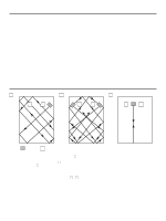
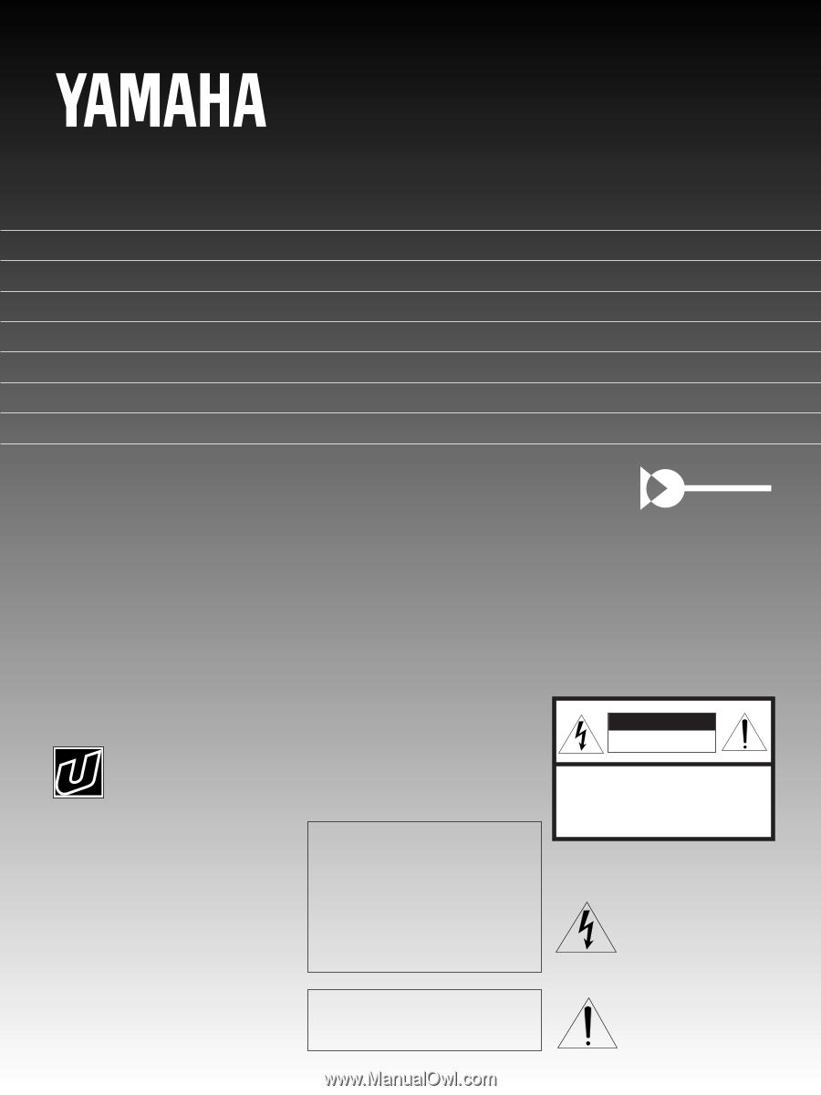
sound quality for various listening conditions. • A newly employed AUTO POWER ON/OFF switch saves you the trouble of pressing the POWER switch when turning the power on and off. PLACEMENT A B C ( : subwoofer, : main speaker) If using one subwoofer, it is recommended to place it on the outside - Yamaha YST-SW150 | Owner's Manual - Page 5
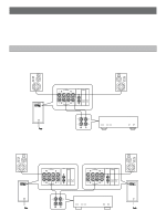
amplifier. Choose one of the ways shown below according to your audio system. Also, refer to the owner's manual for each component to be connected to this unit. CONNECTING TO SPEAKER TERMINALS OF THE AMPLIFIER Disconnect your main speakers from the amplifier and connect them to this unit. If using - Yamaha YST-SW150 | Owner's Manual - Page 6
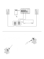
If your amplifier has two sets of speaker terminals Right speaker This unit OUTPUT TO SPEAKERS INPUT2 AUTO PHASE POWER FROM AMPLIFIER INPUT1 ON OFF NOM REV OUTPUT TO SPEAKERS INPUT2 AUTO PHASE POWER FROM AMPLIFIER INPUT1 ON OFF NOM REV Left speaker To AC outlet A B Amplifier (Both - Yamaha YST-SW150 | Owner's Manual - Page 7
. • To connect with a YAMAHA DSP amplifier, connect the LOW PASS (or SUBWOOFER etc.) terminal on the rear of the DSP amplifier to either the left (L) or right (R) INPUT 2 terminal. If using one unit Left speaker This unit OUTPUT TO SPEAKERS INPUT2 AUTO PHASE POWER FROM AMPLIFIER INPUT1 ON OFF - Yamaha YST-SW150 | Owner's Manual - Page 8
AND THEIR FUNCTIONS Front panel POWER HIGH CUT VOLUME 40 Hz 140 Hz 0 10 YST-SW150 POWER HIGH CUT VOLUME YST-SW80 POWER HIGH CUT VOLUME 40 Hz 140 Hz 0 10 12 3 4 50 Hz 150 Hz 0 10 12 3 4 Rear panel OUTPUT TO SPEAKERS INPUT2 AUTO PHASE POWER FROM AMPLIFIER INPUT1 ON OFF - Yamaha YST-SW150 | Owner's Manual - Page 9
YST-SW150 POWER HIGH CUT VOLUME YST-SW80 POWER HIGH CUT VOLUME 40 Hz 140 Hz 0 10 2 5 1, 4 Rear panel OUTPUT TO SPEAKERS 50 Hz 150 Hz 0 10 2 5 1, 4 INPUT2 AUTO PHASE POWER main speakers' minimum reproduceable frequency can be looked up in the speakers' catalog or owner's manual. 9 - Yamaha YST-SW150 | Owner's Manual - Page 10
with a 4" or 5" acoustic suspension, 2 way system dB YST-SW150 YST-SW80 dB YST-SW150 HIGH CUT VOLUME 90 YST-SW80 HIGH CUT VOLUME 80 70 90 80 YST-SW150 70 YST-SW80 40 Hz 140 Hz 0 10 50 Hz 150 Hz 0 10 60 50 Main speaker's response 60 Main speaker's response 50 PHASE-Set to - Yamaha YST-SW150 | Owner's Manual - Page 11
negativeimpedance drive. Active Servo Processing speakers reproduce the bass frequencies through an "air woofer", which is a port or opening in the speaker's cabinet. This opening is used instead of, and performs the functions of, a woofer in a conventionally designed speaker system. Thus, signals - Yamaha YST-SW150 | Owner's Manual - Page 12
the walls. SPECIFICATIONS YST-SW150 Type Active Servo Processing Subwoofer System Speaker Unit 20 cm (7-7/8") cone woofer (JA2156) magnetic-shield type x 2 Amplifier Output 120W/5 ohms High-Cut Filter 40 Hz-140 Hz (-24 dB/oct.) Frequency Response 20 Hz-160 Hz (-10 dB) Power Supply U.S.A. and
-
 1
1 -
 2
2 -
 3
3 -
 4
4 -
 5
5 -
 6
6 -
 7
7 -
8
-
9
-
10
-
11
-
12
 |
 |
IMPORTANT!
Please record the serial number of this
unit in the space below.
Model:
Serial No.:
The serial number is located on the rear
of the unit.
Retain this Owner’s Manual in a safe
place for future reference.
WARNING
TO REDUCE THE RISK OF FIRE OR
ELECTRIC SHOCK, DO NOT EXPOSE
THIS UNIT TO RAIN OR MOISTURE.
RISK OF ELECTRIC SHOCK
DO NOT OPEN
CAUTION:
TO REDUCE THE RISK OF
ELECTRIC SHOCK, DO NOT REMOVE
COVER (OR BACK), NO USER-SERVICEABLE
PARTS INSIDE, REFER SERVICING TO
QUALIFIED SERVICE PERSONNEL.
The lightning flash with arrowhead
symbol, within an equilateral triangle,
is intended to alert you to the
presence of uninsulated “dangerous
voltage” within the product’s
enclosure that may be of sufficient
magnitude to constitute a risk of
electric shock to persons.
The exclamation point within an
equilateral triangle is intended to alert
you to the presence of important
operating and maintenance
(servicing)
instructions in the
literature accompanying the
appliance.
•
Explanation of Graphical Symbols
CAUTION
Active Servo Processing Subwoofer System
Built-in 100W Power Amplifier (YST-SW150)
Built-in 70W Power Amplifier (YST-SW80)
2 Way Selectability for Connections
High Frequency Cut-off Point (HIGH CUT) Control
PHASE Switch
AUTO POWER ON/OFF Switch
OWNER’S MANUAL
CONTENTS
Safety Instructions
...................
2
Features
...................................
4
Placement
................................
4
Connections
.............................
5
Controls and Their Functions
.......
8
Adjusting Volume
.....................
9
Active Servo Technology
........
11
Troubleshooting
......................
12
Specifications
.........................
12
YST-SW150/80
Thank you for selecting this YAMAHA Subwoofer System.
Active Servo
Technology