Zenith P42W46X Service Manual - Page 10
Adjustment of White Balance, Auto RGB Color Balance, Auto Component Color Balance - power supply
 |
UPC - 044642701499
View all Zenith P42W46X manuals
Add to My Manuals
Save this manual to your list of manuals |
Page 10 highlights
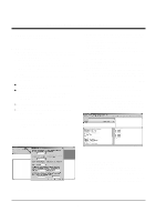
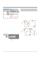
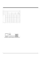
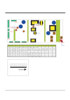
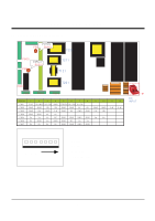
ADJUSTMENT INSTRUCTIONS 2) After turning RV401, voltage of D.M.M adjustment as same as Va voltage which on label of panel right/top. (Deviation; ±0.5V) 5-4. Adjustment Method for P/No. 3501V00182A B/D (1) Va Adjustment 1) After receiving 100% Full White Pattern, HEAT RUN. 2) Connect + terminal of D.M.M to Va pin of P805, connect - terminal to GND pin of P805. 3) After turning RV601, voltage of D.M.M adjustment as same as Va voltage which on lable of panel right/top (Deviation; ±0.5V) (2) Vs Adjustment 1) Connect + terminal of D.M.M to Vs pin of P805, connect - terminal to GND pin of P805. 2) After turning RV401, voltage of D.M.M adjustment as same as Va voltage which on label of panel right/top. (Deviation; ±0.5V) 6. Adjustment of White Balance 6-1. Required Equipment Color Analyzer (CA-100 or same product) 6-2. Connection Diagram of Equipment for Measuring 216 Gray Level Full Size Pattern AV Signal Input 60Hz Window RS-232C Serial Communication MSPG-2100 or MSTG-5200 (Fig 6) White Balance Adjustment (2) Supply Gray Pattern (216 Level Full Size Pattern) signal to VIDEO input. (AV2 Input 60Hz) (Refer to Fig. 6) (3) To adjust, stick sensor to 216 Gray Level Pattern, press ADJ key twice(White Balance) on remote control. For adjustment and D, E on reomte control for adjustment mode to select Red Gain and Blue Gain, press VOL +, Key and adjust it until color coordination becomes as below. X; 0.283±0.003, Y; 0.297±0.003 Color Temperature; 9,300°K±500°K (4) Exit adjustment mode using A Key. 7. Auto RGB Color Balance 7-1. Pattern Equipment PC Pattern Generator (VG828, VG854, 801GF, MSP3240A) (16 Gray Scale Pattrtn output(RGB output Level: 0.7Vp-p) 7-2. Method of Auto RGB Color Balance (1) Input RGB Source : 16 Gray Scale Pattern output (RGB output Level : 0.7Vp-p) (2) Press ADJ KEY on R/C for adjustment. (3) Press Vol. + KEY and operate To SET. (4) Auto-RGB OK means completed adjustment. 8. Auto Component Color Balance 8-1. Pattern Equipment MSP3240A or same product (16 Gray Scale Pattern output(Component output Level: 0.7Vp-p) 8-2. Method of Auto RGB Color Balance (1) Input RGB Source : Component 480p/576p 16 Gray Scale Pattern At this time, except Pb and Pr signal, only Y signal insert. (2) Press ADJ KEY on R/C for adjustment. (3) Press Vol. + KEY and operate To set. (4) Auto-RGB OK means completed adjustment. 6-3. Adjustment of White Balance O Operate the Zero-calibration of the CA-100, then stick sensor to PDP module surface when you adjust. O For manual adjustment, it is also possible by the following sequence. (1) Select white pattern of heat-run mode by pressing power on key on remote control for adjustment then operate heat run more than 15 minutes. (Fig 7) Auto RGB/ Component Color Balance Test Pattern - 10 -
-
 1
1 -
2
-
3
-
4
-
 5
5 -
 6
6 -
 7
7 -
 8
8 -
 9
9 -
 10
10 -
 11
11 -
 12
12 -
 13
13 -
 14
14 -
 15
15 -
16
-
17
-
18
-
19
-
20
-
21
-
22
-
23
-
24
-
25
-
26
-
27
-
28
-
29
-
30
-
31
-
32
-
33
-
34
-
35
-
36
-
37
-
38
-
39
-
40
-
41
 |
 |
