Zenith P42W46X Service Manual - Page 11
Auto Adjustment MapRS-232C, DDC Data Input - model
 |
UPC - 044642701499
View all Zenith P42W46X manuals
Add to My Manuals
Save this manual to your list of manuals |
Page 11 highlights
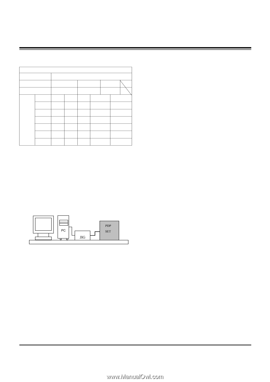
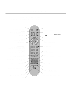
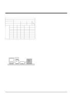
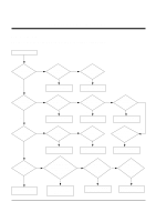
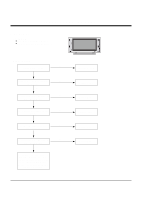
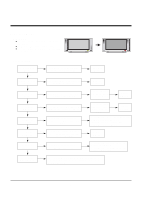
ADJUSTMENT INSTRUCTIONS 9. Auto Adjustment Map(RS-232C) Type RF-043A RS232 Baud Rate Data bit Stop bit Parity 115200 8 1 NONE Index Cmd1 Cmd2 Data Min Value Max Value R Gain j a 00(00) 255(FF) G Gain j b Protocol B Gain j c Setting R Offset j d 00(00) 00(00) 00(00) 255(FF) 255(FF) 255(FF) G Offset j e 00(00) 255(FF) B Offset j f 00(00) 255(FF) 6) If Check Sum is not 53, repeat 3) ~ 4). 7) If Check Sum is 53, DDC data for Analog-RGB input is completed. (2) DDC Data input for Digital-RGB(DVI) 1) Connect PC Serial to DVI Cable of jig for DDC adjustment to DVI terminal (DVI Jack). 2) Operate S/W for DDC record and select DDC data for digital RGB in model menu. 3) Operate EDID Write command. 4) Operate EDID Read command and check whether Check sum is D2(1page), BF(2page). 5) If Check sum is not D2(1page), BF(2page), repeat 3) ~ 4). 6) If Check sum is D2(1page), BF(2page), DDC data for Analog-RGB input is completed. 10. DDC Data Input 10-1. Required Test Equipment (1) A jig for adjusting PC, DDC (PC serial to D-sub Connection equipment) (2) S/W for writing DDC (EDID Data Write & Read) (3) D-sub 15P Cable, D-Sub to DVI Connector (Connect to DVI Jack) 10-2. Setting of Device 10-3. Preparation for Adjustment (1) Set devices as above and turn the PC, jig on. (2) Put S/W for writing DDC (EDID data Write & Read) into operation. (operated in DOS mode.) 10-4. Sequence of Adjustment (1) DDC Data Input for Analog-RGB 1) Put the set on the table and turn the power on. 2) Connect PC Serial to D-sub 15P Cable of jig for DDC adjustment to RGB terminal (D-Sub 15Pin). 3) Operate S/W for DDC record and select DDC data for Analog RGB in Model Menu. 4) Operate EDID Write command. 5) Operate EDID Read command and check whether Check Sum is 53. - 11 -
-
 1
1 -
2
-
3
-
4
-
5
-
 6
6 -
 7
7 -
 8
8 -
 9
9 -
 10
10 -
 11
11 -
 12
12 -
 13
13 -
 14
14 -
 15
15 -
 16
16 -
17
-
18
-
19
-
20
-
21
-
22
-
23
-
24
-
25
-
26
-
27
-
28
-
29
-
30
-
31
-
32
-
33
-
34
-
35
-
36
-
37
-
38
-
39
-
40
-
41
 |
 |