Zenith P42W46X Service Manual - Page 16
Protect Mode - only sound
 |
UPC - 044642701499
View all Zenith P42W46X manuals
Add to My Manuals
Save this manual to your list of manuals |
Page 16 highlights
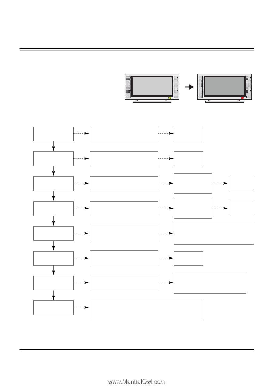
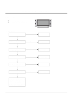
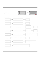
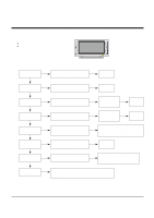
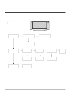
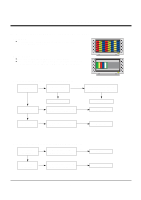
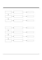
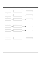
TROUBLE SHOOTING GUIDE 3. Protect Mode (1) Symptom ¯ After once shining, it does not discharge minutely from module ¯ The Rely falls(The sound is audible "click") ¯ It is converted with the color where the front LED is red from green. (2) Check follow Is normal the Power No Board? Yes Is normal the each No connector? Yes Is normal the No Y- Board? Yes Is normal the No Z- Board? Yes Is normal the No X- Board? Yes Is normal the No Ctrl Board? Yes Is normal the No VSC Board? Yes Is normal the No COF of X, Y, Z? Is output the normality Low/High voltage except Stand-by 5V? No Replace Power Board. After connecting well each connector, No the normality it operates? Replace connector. Is normal the output Is normal the Fuse(F52) on Y-B/D? Yes voltage after remove Yes (In case of open is replace) P5, P6 connector of Y-B/D? Replace Y-Board. Is normal the output Is normal the Fuse(FS1, FS2) on Z- Yes voltage after remove Yes B/D? (In case of open is replace) P1 connector of Z-B/D? Replace Z-Board. Is normal the output voltage after Yes remove P1, 2, 3, 4, 6, 7 connector of X-B/D? After remove P1, P2, P3, P4 output voltage normality: Replace Right X-B/D After remove P6, P7 output voltage normality: Replace Left X-B/D Is normal the output voltage after Yes remove P1, 2, 101, 300, 701, 702 connector of Ctrl-B/D? Replace X-Board. Is normal the output voltage after Yes After remove P1000 normal operation: Replace Analog Board remove P1000, P1200? After remove P1200 normal operation: Replace Digital Board After crisis COF of each board, check the normality operates. If in case normality operates, correspondence COF Fail is replace the module. - 16 -
-
 1
1 -
2
-
3
-
4
-
5
-
6
-
7
-
8
-
9
-
10
-
 11
11 -
 12
12 -
 13
13 -
 14
14 -
 15
15 -
 16
16 -
 17
17 -
 18
18 -
 19
19 -
 20
20 -
 21
21 -
22
-
23
-
24
-
25
-
26
-
27
-
28
-
29
-
30
-
31
-
32
-
33
-
34
-
35
-
36
-
37
-
38
-
39
-
40
-
41
 |
 |