Zenith P42W46X Service Manual - Page 8
Adjustment Instructions - parts
 |
UPC - 044642701499
View all Zenith P42W46X manuals
Add to My Manuals
Save this manual to your list of manuals |
Page 8 highlights
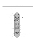
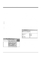
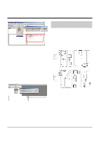
ADJUSTMENT INSTRUCTIONS 1. Application Object These instructions apply to the RF-043A Chassis. 2. Specification (1) Because this is not a hot chassis, it is not necessary to use an isolation transformer. However, the use of isolation transformer will help protect test instrument. (2) Adjustment must be done in the correct order. (3) The adjustment must be performed in the circumstance of 25±5°C of temperature and 65±10% of relative humidity if there is no specific designation. (4) The input voltage of the receiver must keep 100~220V, 50/60Hz. (5) The receiver must be operated for about 15 minutes prior to the adjustment. O After RGB Full white HEAT-RUN Mode, the receiver must be operated prior to adjustment. O Enter into HEAT-RUN MODE 1) Press the POWER ON KEY on R/C for adjustment. 2) OSD display and screen display 100% full WHITE PATTERN. [ Set is activated HEAT-RUN without signal generator in this mode. [ Single color pattern(RED/BLUE/GREEN) of HEAT-RUN mode uses to check PANEL. Caution) If you turn on a still screen more than 20 minutes (Especially digital pattern, cross hatch pattern), a after image may be occur in the black level part of the screen. (2) After installing the Gprobe, [Option -> Connection Setup] or click the icon indicated in the picture and then setup as below the picture. (In case of the port (second one), set to the serial port of the connected PC. The other only have to be set as below the picture.) (3) After finishing inputs, click the button [OK] to complete the connection setup. 3-2. Confirming the G-prove (1) Connect Rs232 cable and then turn on the power. If communication is correct, the message is showed like in the left output terminal. (2) If the message is not showed, push the [INSTART] button of the adjust remocon twice, and change the right selection of the [System Control -> RS-232 Host] from GProbe to PC. ** If it is impossible to check the OSD, push the [TILT] button of the adjust remocon. Then, the message which is "Starting Gprove..." comes up. From this time, communication is operated correctly. However, you have to push the [TILT] button again in case of turning on Main Power. ** If you want to check again whether commnunication is on or not, input "test" and push the Enter key on the right input terminal. If communication is on, the message of "Test passed." will come up 3. Channel memory 3-1. Setting up the G-prove (Fig 2) (Fig 1) (1) Install the GProve. (GProve4.4.0.2.exe) 3-3. Channel memory method (1) Click [Command -> Batch]. (2) When the window of [Batch] is showed, enter the text file (Ch_Memory-RZ_PX10.txt) in the right blank of the File. (3) Click the button [OK] to write CH information in the EEPROM. (4) It means the completion of the CH memory download that the message of right output terminal is showed as below. -8-
-
 1
1 -
2
-
 3
3 -
 4
4 -
 5
5 -
 6
6 -
 7
7 -
 8
8 -
 9
9 -
 10
10 -
 11
11 -
 12
12 -
 13
13 -
14
-
15
-
16
-
17
-
18
-
19
-
20
-
21
-
22
-
23
-
24
-
25
-
26
-
27
-
28
-
29
-
30
-
31
-
32
-
33
-
34
-
35
-
36
-
37
-
38
-
39
-
40
-
41
 |
 |