ZyXEL P-2812HNU-F1 User Guide - Page 351
Antenna Characteristics, Frequency, Radiation Pattern, Antenna Gain, Types of Antennas for WLAN, - 5ghz
 |
View all ZyXEL P-2812HNU-F1 manuals
Add to My Manuals
Save this manual to your list of manuals |
Page 351 highlights
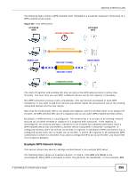
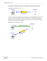
Appendix D Wireless LANs Antenna Characteristics Frequency An antenna in the frequency of 2.4GHz (IEEE 802.11b and IEEE 802.11g) or 5GHz (IEEE 802.11a) is needed to communicate efficiently in a wireless LAN Radiation Pattern A radiation pattern is a diagram that allows you to visualize the shape of the antenna's coverage area. Antenna Gain Antenna gain, measured in dB (decibel), is the increase in coverage within the RF beam width. Higher antenna gain improves the range of the signal for better communications. For an indoor site, each 1 dB increase in antenna gain results in a range increase of approximately 2.5%. For an unobstructed outdoor site, each 1dB increase in gain results in a range increase of approximately 5%. Actual results may vary depending on the network environment. Antenna gain is sometimes specified in dBi, which is how much the antenna increases the signal power compared to using an isotropic antenna. An isotropic antenna is a theoretical perfect antenna that sends out radio signals equally well in all directions. dBi represents the true gain that the antenna provides. Types of Antennas for WLAN There are two types of antennas used for wireless LAN applications. • Omni-directional antennas send the RF signal out in all directions on a horizontal plane. The coverage area is torus-shaped (like a donut) which makes these antennas ideal for a room environment. With a wide coverage area, it is possible to make circular overlapping coverage areas with multiple access points. • Directional antennas concentrate the RF signal in a beam, like a flashlight does with the light from its bulb. The angle of the beam determines the width of the coverage pattern. Angles typically range from 20 degrees (very directional) to 120 degrees (less directional). Directional antennas are ideal for hallways and outdoor point-to-point applications. Positioning Antennas In general, antennas should be mounted as high as practically possible and free of obstructions. In point-to-point application, position both antennas at the same height and in a direct line of sight to each other to attain the best performance. For omni-directional antennas mounted on a table, desk, and so on, point the antenna up. For omni-directional antennas mounted on a wall or ceiling, point the antenna down. For a single AP application, place omni-directional antennas as close to the center of the coverage area as possible. For directional antennas, point the antenna in the direction of the desired coverage area. P-2812HNU(L)-Fx Series User's Guide 351
-
 1
1 -
2
-
3
-
4
-
5
-
6
-
7
-
8
-
9
-
10
-
11
-
12
-
13
-
14
-
15
-
16
-
17
-
18
-
19
-
20
-
21
-
22
-
23
-
24
-
25
-
26
-
27
-
28
-
29
-
30
-
31
-
32
-
33
-
34
-
35
-
36
-
37
-
38
-
39
-
40
-
41
-
42
-
43
-
44
-
45
-
46
-
47
-
48
-
49
-
50
-
51
-
52
-
53
-
54
-
55
-
56
-
57
-
58
-
59
-
60
-
61
-
62
-
63
-
64
-
65
-
66
-
67
-
68
-
69
-
70
-
71
-
72
-
73
-
74
-
75
-
76
-
77
-
78
-
79
-
80
-
81
-
82
-
83
-
84
-
85
-
86
-
87
-
88
-
89
-
90
-
91
-
92
-
93
-
94
-
95
-
96
-
97
-
98
-
99
-
100
-
101
-
102
-
103
-
104
-
105
-
106
-
107
-
108
-
109
-
110
-
111
-
112
-
113
-
114
-
115
-
116
-
117
-
118
-
119
-
120
-
121
-
122
-
123
-
124
-
125
-
126
-
127
-
128
-
129
-
130
-
131
-
132
-
133
-
134
-
135
-
136
-
137
-
138
-
139
-
140
-
141
-
142
-
143
-
144
-
145
-
146
-
147
-
148
-
149
-
150
-
151
-
152
-
153
-
154
-
155
-
156
-
157
-
158
-
159
-
160
-
161
-
162
-
163
-
164
-
165
-
166
-
167
-
168
-
169
-
170
-
171
-
172
-
173
-
174
-
175
-
176
-
177
-
178
-
179
-
180
-
181
-
182
-
183
-
184
-
185
-
186
-
187
-
188
-
189
-
190
-
191
-
192
-
193
-
194
-
195
-
196
-
197
-
198
-
199
-
200
-
201
-
202
-
203
-
204
-
205
-
206
-
207
-
208
-
209
-
210
-
211
-
212
-
213
-
214
-
215
-
216
-
217
-
218
-
219
-
220
-
221
-
222
-
223
-
224
-
225
-
226
-
227
-
228
-
229
-
230
-
231
-
232
-
233
-
234
-
235
-
236
-
237
-
238
-
239
-
240
-
241
-
242
-
243
-
244
-
245
-
246
-
247
-
248
-
249
-
250
-
251
-
252
-
253
-
254
-
255
-
256
-
257
-
258
-
259
-
260
-
261
-
262
-
263
-
264
-
265
-
266
-
267
-
268
-
269
-
270
-
271
-
272
-
273
-
274
-
275
-
276
-
277
-
278
-
279
-
280
-
281
-
282
-
283
-
284
-
285
-
286
-
287
-
288
-
289
-
290
-
291
-
292
-
293
-
294
-
295
-
296
-
297
-
298
-
299
-
300
-
301
-
302
-
303
-
304
-
305
-
306
-
307
-
308
-
309
-
310
-
311
-
312
-
313
-
314
-
315
-
316
-
317
-
318
-
319
-
320
-
321
-
322
-
323
-
324
-
325
-
326
-
327
-
328
-
329
-
330
-
331
-
332
-
333
-
334
-
335
-
336
-
337
-
338
-
339
-
340
-
341
-
342
-
343
-
344
-
345
-
 346
346 -
 347
347 -
 348
348 -
 349
349 -
 350
350 -
 351
351 -
 352
352 -
 353
353 -
 354
354 -
 355
355 -
 356
356 -
357
-
358
-
359
-
360
-
361
-
362
-
363
-
364
-
365
-
366
-
367
-
368
-
369
-
370
-
371
-
372
-
373
-
374
-
375
-
376
-
377
-
378
-
379
-
380
-
381
-
382
-
383
-
384
-
385
-
386
-
387
-
388
-
389
-
390
-
391
-
392
-
393
-
394
-
395
-
396
-
397
-
398
-
399
-
400
-
401
-
402
-
403
-
404
-
405
-
406
-
407
-
408
-
409
-
410
-
411
-
412
-
413
-
414
-
415
-
416
-
417
-
418
-
419
-
420
-
421
-
422
 |
 |