eMachines D620 Service Guide
eMachines D620 Manual
 |
View all eMachines D620 manuals
Add to My Manuals
Save this manual to your list of manuals |
eMachines D620 manual content summary:
- eMachines D620 | Service Guide - Page 1
eMachines D620 Service Guide Service guide files and updates are available on the ACER/CSD web; for more information, please refer to http://csd.acer.com.tw PRINTED IN TAIWAN - eMachines D620 | Service Guide - Page 2
Revision History Please refer to the table below for the updates made on eMachines D620 service guide. Date Chapter Updates ii - eMachines D620 | Service Guide - Page 3
© 2008 by Acer Incorporated. All rights reserved. No part of this publication may be reproduced, transmitted, transcribed, stored in a retrieval system, or translated into any language or computer language, in any form or by any means, electronic, mechanical, magnetic, optical, chemical, manual or - eMachines D620 | Service Guide - Page 4
in this guide is subject to change without notice. Acer Incorporated makes manual is sold or licensed "as is". Should the programs prove defective following their purchase, the buyer (and not Acer Incorporated, its distributor, or its dealer) assumes the entire cost of all necessary servicing - eMachines D620 | Service Guide - Page 5
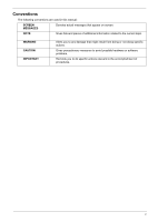
Conventions The following conventions are used in this manual: SCREEN MESSAGES Denotes actual messages that appear on screen. NOTE Gives bits and pieces of additional information related to the current topic. WARNING CAUTION IMPORTANT Alerts you to any damage that might result from - eMachines D620 | Service Guide - Page 6
card, modem, or extra memory capability). These LOCALIZED FEATURES will NOT be covered in this generic service guide. In such cases, please part number change is made, it will not be noted in the printed Service Guide. For ACER-AUTHORIZED SERVICE PROVIDERS, your Acer office may have a DIFFERENT part - eMachines D620 | Service Guide - Page 7
• AMD Athlon™ 2650e processor or higer • AMD RS690MC/SB600 chipset • IEEE 802.11b/g Display and Graphics • 14.1" WXGA TFT LCD, 1280 x 800 pixel resolution • Built-in AMD RS690MC (Marketing name: ATI Radeon™ Xpress 1200 Graphics, integrated graphics card) Storage Subsystem • 2.5" hard disk drive - eMachines D620 | Service Guide - Page 8
• 88-/89-key keyboard • Touchpad pointing device I/O Interface • Four USB 2.0 ports • External display (VGA) port • Headphones/speaker/line-out jack • Microphone-in jack • Ethernet (RJ-45) port • DC-in jack for AC adaptor Power Subsystem • ACPI 3.0 • 48.8 W 4400 mAh Li-ion battery pack (6-cell - eMachines D620 | Service Guide - Page 9
around your new eMachines computer. Top view p # Icon 1 2 Item Integrated webcam Microphone Description Web camera for video communication. (only for certain models) Internal microphone for sound recording. 3 Display screen Also called Liquid-Crystal Display (LCD), display computer output - eMachines D620 | Service Guide - Page 10
4 HDD Indicates when the hard disk drive is active. Num Lock Caps Lock Lights up when Num Lock is activated. Lights up when Caps Lock is activated. 5 Keyboard For entering data into your computer. 6 Palmrest Comfortable support area for your hands when you use the computer. 7 Touchpad - eMachines D620 | Service Guide - Page 11
Closed front view # Icon 1 2 Item Speakers Microphone-in jack Description Left and right speakers deliver stereo audio output. Accepts inputs from external microphones. 3 Headphones/speaker/ Connects to audio line-out devices (e.g., speakers, line-out jack headphones). 4 Wireless - eMachines D620 | Service Guide - Page 12
eject button* 5 Emergency eject hole* NOTE: Location depends on model Internal optical drive; accepts CDs or DVDs. Lights up when the optical drive is active. Ejects the optical disk from the drive. Ejects the optical drive tray when the computer is turned off. Note: Insert a paper clip to the - eMachines D620 | Service Guide - Page 13
1 Item Battery bay 2 Battery lock 3 Hard disk bay Description Houses the computer's battery pack. Locks the battery in position. Houses the computer's hard disk (secured with screws). 4 Memory compartment Houses the computer's main memory. 5 Battery release latch Releases the battery for - eMachines D620 | Service Guide - Page 14
its surface. This means the cursor responds as you move your finger across the surface of the touchpad. The central location on the palmrest provides optimum comfort and support. Touchpad Basics The following items show you how to use the touchpad with two-click buttons. 12 3 • Move your finger - eMachines D620 | Service Guide - Page 15
fingers - dry and clean. The touchpad is sensitive to finger movement; hence, the lighter the touch, the better the response. Tapping too hard will not increase the touchpad's responsiveness. NOTE: By default, vertical and horizontal scrolling is enabled on your touchpad. It can be disabled under - eMachines D620 | Service Guide - Page 16
separate cursor, lock, Windows, function and special keys. Lock Keys and Embedded Numeric Keypad The keyboard has three lock keys certain models. When Scroll Lock is on, the screen moves one line up or down when you press the located on the upper right corner of the keycaps. To simplify the keyboard - eMachines D620 | Service Guide - Page 17
Display the System Properties dialog box < > + : Restore minimized windows to the desktop < > + : Cycle through programs on the taskbar by using Windows Flip 3-D < > + : Bring all gadgets to the front and select Windows Sidebar + < > + : Search for computers (if you - eMachines D620 | Service Guide - Page 18
computer's controls like screen brightness, volume output and the BIOS utility. To activate Screen blank Touchpad toggle Switches display output between the display screen, external monitor (if connected) and both. Turns the display screen backlight off to save power. Press any key to return. Turns - eMachines D620 | Service Guide - Page 19
Euro symbol 1. Open a text editor or word processor. 2. Either press < > at the bottom-right of the keyboard, or hold and then press the key at the upper-center of the keyboard. NOTE: Some fonts and software do not support the Euro symbol. Please refer to www.microsoft.com/ typography - eMachines D620 | Service Guide - Page 20
Processor Item CPU type Clock Speeds L2 Cache Front Side Bus Socket Interface TDP (Thermal Design Power) Specification AMD Athlon 2650e (Acer PN:KC.AE002.265) 1.6 GHz 512KB 800 MHz AM 2 socket (or called Socket AM2; DT processor) 15W Processor Specification Processor# Athlon 2650e CPU - eMachines D620 | Service Guide - Page 21
Hard Disk Drive Interface Item Data buffer (MB) Media transfer rate (Mbytes/s, max) Interface transfer rate (Mbytes/s, max) Voltage tolerance Specification 8 775 150 5V(DC) +/- 5% 8 794 (MK3252GSX) N/A 5V(DC) +/- 5% 8 933 150 5V(DC) +/- 5% BIOS Item BIOS vendor BIOS Version Supported protocols - eMachines D620 | Service Guide - Page 22
Memory Technology 4.0 (8MB of dedicated system memory, up to 256MB of shared system memory), supporting Microsoft DirectX 9 and DirectX 10 Maximum resolutions supported built-in Acer 3DSonic stereo speakers, Supports high definition audio Onboard Gigabit Ethernet, PCI-E interface, support ASF 2.0 - eMachines D620 | Service Guide - Page 23
Bluetooth Module Item Vendor Model name Protocol Connector type Specification N/A (no Bluetooth function available on this model) N/A N/A N/A Chapter 1 17 - eMachines D620 | Service Guide - Page 24
Acer FineTouch keyboard hotkey controls, embedded numeric keypad, multi-language support, three easy-launch buttons, and one front-access communication switch Combo Drive Interface Item Vendor Model name Drive type Data transfer rate Buffer Memory Interface Applicable disc format Power supply - eMachines D620 | Service Guide - Page 25
name Drive type Data transfer rate Buffer Memory Interface Applicable disc format Power supply Specification Toshiba Pioneer HLDS TS-L633A DVR-TD08RS GT10N Internal Slim DVD/CD writer Write: Write: Write: • CD-R: 24X CAV • CD-R: 24X • CD-R: 24X • CD-RW: 24X CAV • CD-RW: 24X • CD-RW - eMachines D620 | Service Guide - Page 26
Model name Drive type Data transfer rate Buffer Memory Interface Applicable disc format Power supply Specification Sony Sony PLDS AD-7590S AD7580S DS-8A2S Internal Slim DVD/CD writer Write: Write: Write: • CD-R: 24X CAV • CD-R: 24X • CD-R: 24X • CD-RW: 24X CAV • CD-RW: 24X • CD-RW - eMachines D620 | Service Guide - Page 27
Typical white luminance (cd/ 200 m2) also called brightness Contrast ratio 400:1 Response time (optical rise 16 time + fall time) (msec) Power consumption (watt) 5.1 Supply voltage (v) 3.3 Backlight 1 CCFL Outline dimensions (mm) 319.5 x 205.5 x 5.2 Weight (g) 400 CMO N141I3-L02 (Glare - eMachines D620 | Service Guide - Page 28
S0): Individual devices such as the CPU and hard disk may be power managed in this state. • Suspend to RAM (S3): CPU set power down, VGA Suspend, PCMCIA Suspend, Audio Power Down, Hard Disk Power Down, CD-ROM Power Down, and Super I/O Low Power mode. • Save to Disk (S4): Also called Hibernation Mode - eMachines D620 | Service Guide - Page 29
problems. Refer to Chapter 4 Troubleshooting when problem arises. Entering BIOS Setup Power on the system to start the system POST process. During bootup, press F2 to enter the BIOS setup screen. NOTE: You must press F2 while the system is booting. This key does not work during any other time. BIOS - eMachines D620 | Service Guide - Page 30
secondary IDE channel. The hard disk drive or optical drive model name is automatically detected by the system. Serial number of devices installed on the secondary IDE channel. Model name of the ATAPI CD/DVD-ROM drive installed in the system. Version number of the BIOS setup utility. Version number - eMachines D620 | Service Guide - Page 31
D2D Recovery Description Set the system time following the hour-minute-second format. Set the date following the weekday-month-day-year format. Total size of system memory detected during POST. Total size of extended memory during POST. Total size of VGA memory. When Enabled, the BIOS splash screen - eMachines D620 | Service Guide - Page 32
Information Phoenix TrustedCore(tm) Setup Utility Main Advanced Security Boot Exit AHCI Mode: Infrared Port: ASF Configuration [Enabled ) Option ROM. AHCI is an interface specification that allows the storage driver to enable advanced SATA features such as Native Command Queuing and hot - eMachines D620 | Service Guide - Page 33
Supervisor Password Set User Password Set Secondary MAS.Disk Password Password on Boot Description Indicates whether a supervisor password has been assigned. Indicates whether a user password has been assigned. Indicates whether a hard disk drive password has been assigned. Press Enter to configure - eMachines D620 | Service Guide - Page 34
Removing a System Password 1. Use the up/down keys to select a password parameter (Set Supervisor Password, Set User Password, or Set Secondary MAS.Disk Password), then press Enter. 2. Enter the current password then press Enter. 3. Press Enter twice without entering anything in the new and confirm - eMachines D620 | Service Guide - Page 35
it reaches an available device. BIOS setup will display an error message if the drive(s) specified is not bootable. Phoenix TrustedCore(tm) Setup Utility Information Main Advanced Security Boot Exit Boot priority order: 1: IDE0: XXXXXXXXXXX-(XX) 2: IDE1: 3: CD/DVD: XXXXXXXXXXX-XXX XX-XXXX - eMachines D620 | Service Guide - Page 36
Phoenix TrustedCore(tm) Setup Utility Information Main Advanced Security Boot Exit Exit Saving Changes Exit Discarding Changes Load Setup Defaults Discard Changes Save Changes Item Specific Help Exit System Setup and save your changes to CMOS. F1 Help Esc Exit Select Item -/+ Change Values - eMachines D620 | Service Guide - Page 37
Disassembly and Replacement This chapter contains step-by-step procedures on how to disassemble the notebook computer for maintenance and troubleshooting. Disassembly Requirements To disassemble different components vary in size. During the disassembly process, group the screws with the corresponding - eMachines D620 | Service Guide - Page 38
Instructions Before proceeding with the disassembly procedure, make sure that you do the following: 1. Turn off the power to the system and all peripherals. 2. Unplug the AC adapter and all power and signal cables from the system. 3. Place the system on a flat, stable surface. 4. Remove the battery - eMachines D620 | Service Guide - Page 39
LCD module disassembly The flowcharts provided in the succeeding disassembly sections illustrate the entire disassembly sequence. Observe the order of the sequence to avoid damage to any of the hardware components. For example, if you want to remove the mainboard, you must first remove the keyboard - eMachines D620 | Service Guide - Page 40
servicing. For example, if you want to remove the mainboard, you must first remove the keyboard, then disassemble the inside assembly frame in that order. TURN OFF POWER AND PERIPHERALS Ax4 Bx1 LOWER COVER UNPLUG POWER CABLES Ex1 OPTICAL DISK DRIVE MODULE Cx2 WLAN BOARD DIMM MODULES HARD DISK - eMachines D620 | Service Guide - Page 41
Loosen the four screws (A) on the lower cover. Step 1~4 Size (Quantity) M2 x L4 (4) 4. Remove the screw (B) on the lower cover. Step Size (Quantity) 5 M2 x L18 (1) 5. Use a plastic screw driver to pry open the lower cover. Color Black Color Black Chapter 3 Torque 1.6 kgf-cm Torque 1.6 kgf - eMachines D620 | Service Guide - Page 42
from the lower case. Removing the DIMM 1. See "Removing the Battery Pack" on page 51. 2. See "Removing the Lower Cover" on page 51. 3. See "Removing the Lower Cover" on page 51. 4. Push out the latches on both sides of the DIMM socket to release the DIMM. 5. Remove the DIMM module. 6. Do the - eMachines D620 | Service Guide - Page 43
WLAN board. Step 1~2 Size (Quantity) M2 x L3 (2) 7. Detach the WLAN board from the WLAN socket. Color Silver Torque 1.6 kgf-cm NOTE: When attaching the antennas back to the WLAN board, make sure the cable are routed properly. Chapter 3 53 - eMachines D620 | Service Guide - Page 44
Removing the Hard Disk Drive Module 1. See "Removing the Battery Pack" on page 51. 2. See "Removing the Lower Cover" on page 51. 3. See "Removing the Lower Cover" on page 51. 4. Pull the HDD module out by pulling on the mylar attached to it, gently slide-out the HDD module from its bay. - eMachines D620 | Service Guide - Page 45
5. Remove the HDD rubber enclosure by gently prying open the enclosure, starting on either side (3) and proceeding down the bottom (4) and towards the top of the disk (5), then pull it up to detach from the HDD module (6). NOTE: The HDD on this model does not have the rubber enclosure as above - eMachines D620 | Service Guide - Page 46
Optical Drive Module 1. See "Removing the Battery Pack" on page 51. 2. See "Removing the Lower Cover" on page 51. 3. See "Removing the Lower Cover" on page 51. 4. Turn the base unit over, then remove the screw (E) on the bottom side of the unit. Step 1 Size (Quantity) M2.5 x L6 (1) Color Black - eMachines D620 | Service Guide - Page 47
6. Remove the two screws (F) securing the optical bracket and remove the locker bracket from the optical disk drive module. Step 1-2 Size (Quantity) M2 x L2.5 (2) Color Silver Torque 1.6 kgf-cm Chapter 3 57 - eMachines D620 | Service Guide - Page 48
MAIN UNIT DISASSEMBLY MAIN UNIT Hx2 FAN Ax5 CPU HEATSINK MODULE CPU Gx1 LED INDICATORS BOARD MIDDLE COVER Cx2 KEYBOARD Ex4 LCD MODULE Ax1, Ex11 UPPER CASE Cx4 TOUCHPAD BRACKET ASSEMBLY TOUCHPAD BOARD Cx2 DAUGHTER BOARD Ax1 MAINBOARD Cx2 MODEM BOARD Cx2 FINGERPRINT BOARD BLUETOOTH BOARD Dx2 - eMachines D620 | Service Guide - Page 49
x L5 (torque 1.6) M2.5 x L5 (torque 3.0) Removing the Fan Module 1. See "Removing the Battery Pack" on page 51. 2. See "Removing the Lower Cover" on page 51. 3. See "Removing the Lower Cover" on page 51. 4. Detach the heatsink cable. Part No. 86.00G64.720 86.9A552.3R0 86.9A524.4R0 86.00E33.736 86 - eMachines D620 | Service Guide - Page 50
Step 1-2 Size (Quantity) M2.5 x L5 (2) 7. Remove the fan from the main unit. Color Black Torque 1.6 kgf-cm Removing the CPU Heatsink Module 1. See "Removing the Battery Pack" on page 51. 2. See "Removing the Lower Cover" on page 51. 3. See "Removing the Fan Module" on page 59. 4. Unfasten the - eMachines D620 | Service Guide - Page 51
released lever to release the CPU then remove the CPU from the CPU socket. NOTE: When installing the CPU, make sure to install the CPU with PIN 1 at the corner as shown. IMPORTANT:To prevent any overheating problem, please apply some more thermal grease on the processor when you need to reatch the - eMachines D620 | Service Guide - Page 52
Removing the Middle Cover 1. See "Removing the Battery Pack" on page 51. 2. See "Removing the Lower Cover" on page 51. 3. See "Removing the Lower Cover" on page 51. 4. See "Removing the Fan Module" on page 59. 5. See "Removing the CPU Heatsink Module" on page 60. 6. Open the LCD screen all the way - eMachines D620 | Service Guide - Page 53
Removing the Keyboard 1. See "Removing the Battery Pack" on page 51. 2. See "Removing the Middle Cover" on page 62. 3. Remove the two screws (G) securing the keyboard. Step 1-2 Size (Quantity) M2 x L3 (2) 4. Carefully pry up and out the keyboard and turn it over. Color Silver Torque 1.6 kgf-cm - eMachines D620 | Service Guide - Page 54
the mainboard to remove the keyboard. Removing the LCD Module 1. See "Removing the Battery Pack" on page 51. 2. See "Removing the Lower Cover" on page 51. 3. See "Removing the Lower Cover" on page 51. 4. See "Removing the Fan Module" on page 59. 5. See "Removing the CPU Heatsink Module" on page 60 - eMachines D620 | Service Guide - Page 55
10. Disconnect the touchpad cable. 11. Disconnect the internal microphone cable. 12. Detach the mylar tape securing the mic and antenna cables to the upper case. Chapter 3 65 - eMachines D620 | Service Guide - Page 56
13. Carefully release the cables from the latches as shown. 14. Detach the mylar tape from the LCD coaxial cable. 15. Disconnect the LCD coaxial cable from the mainboard. 66 Chapter 3 - eMachines D620 | Service Guide - Page 57
16. Disconnect the cover switch cable from the mainboard. 17. Turn the system over and remove the two screws (E) from the base of the unit. Step 1~2 Size (Quantity) M2.5 x L6 (2) Color Black 18. Remove the two screws (E) from the left and right hinge of the LCD module. Torque 3.0 kgf-cm Step - eMachines D620 | Service Guide - Page 58
60. 6. See "Removing the CPU" on page 61. 7. See "Removing the Middle Cover" on page 62. 8. See "Removing the Keyboard" on page 63. 9. See "Removing the LCD Module" on page 64. 10. Remove the screw (A) on the top panel. Step 1 Size (Quantity) M2 x L4 (1) Color Black 11. Turn the system over and - eMachines D620 | Service Guide - Page 59
"Removing the Fan Module" on page 59. 5. See "Removing the CPU Heatsink Module" on page 60. 6. See "Removing the CPU" on page 61. 7. See "Removing the Middle Cover" on page 62. 8. See "Removing the Keyboard" on page 63. 9. See "Removing the LCD Module" on page 64. 10. See "Separating the Upper Case - eMachines D620 | Service Guide - Page 60
13. Detach the touchpad bracket from the upper case. 14. Carefully insert the flat screwdriver under the side of the touchpad board and gently pry up the board. 15. Continue prying the board until it releases from the upper case, then remove the board. 70 Chapter 3 - eMachines D620 | Service Guide - Page 61
"Removing the Fan Module" on page 59. 5. See "Removing the CPU Heatsink Module" on page 60. 6. See "Removing the CPU" on page 61. 7. See "Removing the Middle Cover" on page 62. 8. See "Removing the Keyboard" on page 63. 9. See "Removing the LCD Module" on page 64. 10. See "Separating the Upper Case - eMachines D620 | Service Guide - Page 62
CPU Heatsink Module" on page 60. 6. See "Removing the CPU" on page 61. 7. See "Removing the Middle Cover" on page 62. 8. See "Removing the Keyboard" on page 63. 9. See "Removing the LCD RTC battery has been highlighted with the red circle as above image shows. Please detach the RTC battery and - eMachines D620 | Service Guide - Page 63
"Removing the Fan Module" on page 59. 5. See "Removing the CPU Heatsink Module" on page 60. 6. See "Removing the CPU" on page 61. 7. See "Removing the Middle Cover" on page 62. 8. See "Removing the Keyboard" on page 63. 9. See "Removing the LCD Module" on page 64. 10. See "Separating the Upper Case - eMachines D620 | Service Guide - Page 64
"Removing the Fan Module" on page 59. 5. See "Removing the CPU Heatsink Module" on page 60. 6. See "Removing the CPU" on page 61. 7. See "Removing the Middle Cover" on page 62. 8. See "Removing the Keyboard" on page 63. 9. See "Removing the LCD Module" on page 64. 10. See "Separating the Upper Case - eMachines D620 | Service Guide - Page 65
12. Remove the two screws (D) holding the left and right speaker modules to the lower case. Step 1~2 Size (Quantity) M3xL4 (2) 13. Carefully detach the speaker modules as shown. Color Silver Torque 3.0 kgf-cm Chapter 3 75 - eMachines D620 | Service Guide - Page 66
Flowchart LCD MODULE DISASSEMBLY LCD MODULE Ex2, Hx4 LCD BEZEL Hx1 INVERTER BOARD CCD BOARD LCD ASSEMBLY LCD FPC CABLE Ix2 Cx4 LEFT LCD BRACKET Cx4 RIGHT LCD BRACKET Ix1 LEFT HINGE Ix1 RIGHT HINGE MICROPHONE MAIN ANTENNA AUXILIARY ANTENNA Main Screw List Item C E H I LCD BACK PANEL - eMachines D620 | Service Guide - Page 67
"Removing the Fan Module" on page 59. 5. See "Removing the CPU Heatsink Module" on page 60. 6. See "Removing the CPU" on page 61. 7. See "Removing the Middle Cover" on page 62. 8. See "Removing the Keyboard" on page 63. 9. See "Removing the LCD Module" on page 64. 10. Remove the six rounded screw - eMachines D620 | Service Guide - Page 68
Cover" on page 62. 8. See "Removing the Keyboard" on page 63. 9. See "Removing the LCD Module" on page 64. 10. See "Removing the LCD Bezel" on page 77. 11. Remove the screw (H) that hold the board to the panel. Step 1 Size (Quantity) M2.5 x L5 (1) 12. Turn the inverter board over. Color Black - eMachines D620 | Service Guide - Page 69
, then disconnect the 2P cable on the inverter board. 14. Remove the inverter board. Removing the LCD with Brackets 1. See "Removing the Battery Pack" on page 51. 2. See "Removing the Lower Cover" on page 51. 3. 4. See "Removing the Lower Cover" on page 51. 5. See "Removing the Fan Module" on - eMachines D620 | Service Guide - Page 70
cable from the CCD board, then remove the board. 14. Remove the two screws (I) securing the left and right LCD brackets to the LCD back cover. Step 1~2 Size (Quantity) M2.5 x L5 (2) Color Silver 15. Carefully detach the cables from the latches on the LCD bracket as shown. Torque 2.5 kgf-cm 16 - eMachines D620 | Service Guide - Page 71
the FPC cable from the LCD panel. Removing the LCD Brackets 1. See "Removing the Battery Pack" on page 51. 2. See "Removing the Lower Cover" on page 51. 3. See "Removing the Lower Cover" on page 51. 4. See "Removing the Fan Module" on page 59. 5. See "Removing the CPU Heatsink Module" on page 60 - eMachines D620 | Service Guide - Page 72
x L3 (8) Color Silver Removing the LCD Module Hinges 1. See "Removing the Battery Pack" on page 51. 2. See "Removing the Lower Cover" on page 51. 3. See "Removing the Lower Cover" on page 51. 4. See "Removing the Fan Module" on page 59. 5. See "Removing the CPU Heatsink Module" on page 60. 6. See - eMachines D620 | Service Guide - Page 73
and right hinges from the LCD back cover. Removing the Antennas 1. See "Removing the Battery Pack" on page 51. 2. See "Removing the Lower Cover" on page 51. 3. 4. See "Removing the Lower Cover" on page 51. 5. See "Removing the Fan Module" on page 59. 6. See "Removing the CPU Heatsink Module" on page - eMachines D620 | Service Guide - Page 74
the Battery Pack" on page 51. 2. See "Removing the Lower Cover" on CPU Heatsink Module" on page 60. 7. See "Removing the CPU" on page 61. 8. See "Removing the Middle Cover" on page 62. 9. See "Removing the Keyboard" on page 63. 10. See "Removing the LCD Module" on page 64. 11. See "Removing the LCD - eMachines D620 | Service Guide - Page 75
16. Remove the microphone. Chapter 3 85 - eMachines D620 | Service Guide - Page 76
86 Chapter 3 - eMachines D620 | Service Guide - Page 77
tests or repeating the same operation. 3. Do not use any power sources when performing an assembly or disassembly procedures. 4. If any problems occur, you can perform the following visual inspection before you continue. • Power cords are properly connected and secured. • There are no obvious shorts - eMachines D620 | Service Guide - Page 78
the Keyboard Test. If the tests detect a keyboard problem, do the following procedures in sequence to correct the problems. Do not replace a non-defective FRU: 1. Reconnect the keyboard cable. 2. Replace the keyboard. 3. Replace the mainboard. The following auxiliary input devices are supported by - eMachines D620 | Service Guide - Page 79
3. If the power-on indicator does not light up, check if the adapter's power cord is properly connected to the system. 4. If the operational charge does not work, see "Check the Battery Pack" on page 89. Check the Battery Pack Do the following: Using the software to identify whether a problem occurs - eMachines D620 | Service Guide - Page 80
does not work, then replace the FPC on Track Pad PCB. After you use the touchpad, the pointer drifts on the screen for a short time. This self-acting pointer movement will occur when a slight, steady pressure is applied to the touchpad pointer. This symptom is not a hardware problem. No actions are - eMachines D620 | Service Guide - Page 81
in FRU/Action column, if the FRU replacement does not solve the problem, put the original part back in the computer. Do not replace a non-defective FRU. The error messages are listed in the coming pages to indicate the BIOS signals on the screen and the error symptoms classified by functions. If - eMachines D620 | Service Guide - Page 82
• Run "Load Setup Defaults" in BIOS Setup Utility. • Mainboard • Run the BIOS Setup Utility to check if the fixed disk and drive A are properly identified. • CD/DVD-ROM drive • Hard disk drive • Mainboard • Power source (battery pack and power adapter.) See "Power System Check" on page 89. • Ensure - eMachines D620 | Service Guide - Page 83
. LED board Mainboard Power source (battery pack and power adapter). See "Power System Check" on page 89. Reconnect the LCD connector Hard disk drive LCD inverter ID LCD cable LCD Inverter LCD Mainboard Reconnect the LCD connectors. LCD inverter ID LCD cable LCD inverter LCD Mainboard Ensure every - eMachines D620 | Service Guide - Page 84
the local bus IDE Initialize Power Management Load alternate registers with initial POST values Restore CPU control word during warm boot Initialize PCI Bus Mastering devices Initialize keyboard controller BIOS ROM checksum Initialize cache before memory autosize 8254 timer initialization 8237 - eMachines D620 | Service Guide - Page 85
interrupts Initialize POST display service Display prompt "Press F2 to enter SETUP" Disable CPU cache Test RAM between 512 and 640 KB Test extended memory Test extended memory address lines Jump to User Patch1 Configure advanced cache registers Initialize Multi Processor APIC Enable external and - eMachines D620 | Service Guide - Page 86
Extended BIOS Data Area Test and initialize PS/2 mouse Initialize floppy controller Determine number of ATA drives (optional) Initialize hard-disk controllers Initialize local-bus hard-disk controllers Jump to UserPatch2 Build MPTABLE for multi-processor boards Install CD-ROM for boot Clear - eMachines D620 | Service Guide - Page 87
Initialize the CPU Initialize the system timer Initialize system I/O Check force recovery boot Checksum BIOS ROM Go to BIOS Set Huge Segment Initialize Multiprocessor Initialize OEM special code Initialize PIC and DMA Initialize Memory type Initialize Memory size Shadow Boot Block System memory test - eMachines D620 | Service Guide - Page 88
System Check" on page 89. • Battery pack • Power adapter • Hard disk drive & battery connection board • Mainboard • Power source (battery pack and power adapter). See "Power System Check" on page 89. • Battery pack • Power adapter • Hard disk drive & battery connection board • Mainboard 98 Chapter - eMachines D620 | Service Guide - Page 89
in sequence Keyboard (if control is from the keyboard) Hard disk drive Mainboard Press Fn+o and see if the computer enters hibernation mode. Touchpad Keyboard Hard disk connection board Hard disk drive Mainboard LCD cover switch Mainboard Hard disk connection board Hard disk drive Mainboard Chapter - eMachines D620 | Service Guide - Page 90
following in sequence • LCD cover switch • Mainboard • Remove battery pack and let it cool for 2 hours. • Refresh battery (continue use battery until power off, then charge battery). • Battery pack • Mainboard • Reconnect hard disk/CD-ROM drives. • Hard disk connection board • Mainboard Peripheral - eMachines D620 | Service Guide - Page 91
does not work correctly. • Modem phone port • Modem combo board • Mainboard NOTE: If you cannot find a symptom or an error in this list and the problem remains, see "Undetermined Problems" on page 103. Chapter 4 101 - eMachines D620 | Service Guide - Page 92
considered only when a recurring problem exists. When analyzing an intermittent problem, do the following: 1. Run the advanced diagnostic test for the mainboard in loop mode at least 10 times. 2. If no error is detected, do not replace any FRU. 3. If any error is detected, replace the FRU. Rerun the - eMachines D620 | Service Guide - Page 93
check them for damage. If any problems are found, replace the FRU. 3. Remove or disconnect all of the following devices: • Non-Acer devices • Printer, mouse, and other external devices • Battery pack • Hard disk drive • DIMM • CD/DVD-ROM drive • PC cards 4. Power on the computer. 5. Determine if the - eMachines D620 | Service Guide - Page 94
104 Chapter 4 - eMachines D620 | Service Guide - Page 95
USB 2 Port 22 16,17,18,19,20 USB 32.768KHz CCD .3M/1.3M 14 MINI USB BlueTooth 22 KBC SPI I/F BIOS Winbond W25X80-VSS 30 WPC8773L 28 Touch INT. Pad 29 KB 29 LPC DEBUG CONN LDO INPUT DCBATOUT OUTPUT 5V_AUX_S5 3D3V_AUX_S5 Battery Charger INPUTS AD+ BAT+ OUTPUTS DCBATOUT Chapter 5 105 - eMachines D620 | Service Guide - Page 96
Board Layout Top and Bottom View 106 Chapter 5 - eMachines D620 | Service Guide - Page 97
1 Lid switch connector 2 Power key switch 3 Launch key switch 4 LCD cable connector 5 Keyboard connector 6 LED board connector 7 Microphone cable connector 8 Fingerprint board connector (not available on this model) 9 Touchpad board connector 10 Bluetooth cable connector (not - eMachines D620 | Service Guide - Page 98
Insert the Crisis Disk to a USB floppy drive which is attached to the failed machine. c. While the system is turned off, press and hold Fn+ESC, then press Power Button. The system should be powered on with Crisis Recovery process. d. BootBlock BIOS starts to restore the failed BIOS code. Short beeps - eMachines D620 | Service Guide - Page 99
date information available on your regional web or channel. For whatever reasons a part number is changed, it will NOT be noted on the printed Service Guide. For Acer authorized service providers, your Acer office may have a different part number code from those given in the FRU list of this printed - eMachines D620 | Service Guide - Page 100
eMachines D620 Exploded Diagram 1 2 3 4 5 6 7 8 9 10 11 12 13 110 Chapter 4 - eMachines D620 | Service Guide - Page 101
eMachines D620 FRU List ADAPTER 1 1 1 1 BATTERY 1 1 1 1 BOARD NO. PART NAME DESCRIPTION ACER PART NO. N/A ADAPTER 65W DELTA ADT 65W SADP .014 DELTA SADP-65KB 65KB BFJA DELT BFJA LF LEVEL-4 FOR OBL ONLY 13 BATTERY SANYO TM- BTY PACK LI+ 6C 2007A LI-ION 3S2P 2.2AH SANYO SANYO 6 CELL 4400MAH - eMachines D620 | Service Guide - Page 102
BCM4312 T77H030.00 MINICARD WLAN 802.11BG BCM4312 MINICARD ACER PART NO. NI.23600.007 NI.23600.029 N/A POWER CORD 10A CODE US 7A 125V BK 27.T30V1.001 125V US N/A POWER CORD 10A CODE 10A 125V 3P 27.01518.641 125V 3PIN US BK US BK N/A POWER CORD 2.5A CORD USA/W CNS 27.01518.781 125V USA 2.5A - eMachines D620 | Service Guide - Page 103
,1.8M POWER CORD BRAZIL,BLK,1.8M ACER PART NO. 27.03218.021 27.01518.631 27.01518.721 27.01518.551 27.03518.161 27.01518.761 27.01518.0U1 27.01518.A41 N/A LED BOARD CABLE C.A. LED BD FFC BIWA 3RD 50.TK501.001 N/A TOUCHPAD CABLE C.A. T/P FFC BIWA- 50.TK501.002 JIHAW CASE/COVER/BRACKET - eMachines D620 | Service Guide - Page 104
ACER PART NO. ASSY L-CASE YUKON 60.N2401.001 SPEAKER N/A SPEAKER SPEAKER BIWA 23.TK501.002 CASE/COVER/BRACKET ASSEMBLY 7 UPPER CASE W/ COVER SWITCH CABLE ASSY U-CASE YUKON 60.N2401.002 5 MIDDLE COVER ASSY MIDDLE COVER 42.N2401.001 YUKON CPU/PROCESSOR N/A CPU AMD ATHLON IC CPU ATHLON - eMachines D620 | Service Guide - Page 105
24X TSL463A LF W/O BEZEL SATA COMBO SATA TSST/ TS-L463A OLAN COMBO MODULE 24X ODD COMBO 12.7 SONY CRX890S LF W/ SATA CRX890S LF O BEZEL SATA ACER PART NO. KO.02401.006 KO.0240E.009 12 ASSEMBLEY SUPER- ODD NSM8XS FOR 6M.N2401.002 MULTI MODULE 8X YUKON N/A OPTICAL BRACKET BRKT ODD BIWA - eMachines D620 | Service Guide - Page 106
NAME N/A FAN DESCRIPTION ACER PART NO. FAN 14" FAN SUNON 23.TK501.001 CASE/COVER/BRACKET ASSEMBLY N/A HDD BRACKET ASSY HDD BRACKET 33.N2401.002 YUKON HDD/HARD DISK DRIVE N/A HDD 120GB 5400RPM SATA SEAGATE ST9120817AS LF F/ W:3.AAA HDD 120GB SGT SATA ST9120817AS KH.12001.032 HEATSINK 116 - eMachines D620 | Service Guide - Page 107
. N/A PART NAME CPU HEATSINK W/O FAN DESCRIPTION ACER PART NO. ASSY THERMAL SINK 60.N2401.003 FOXCON YUKON KEYBOARD 6 KEYBOARD 14_15KB- KB DARFON NSK- KB.INT00.002 EV2 88KS BLACK US AGL1D UI USI88 INTERNATIONAL (BIG ERGO) 6 KEYBOARD 14_15KB- KB DARFON NSK- KB.INT00.003 EV2 88KS BLACK - eMachines D620 | Service Guide - Page 108
14_15KB- KB DARFON NSK- EV2 88KS BLACK AGL0A AR ARA88 ARABIC(BIG ERGO) KEYBOARD 14_15KBEV2 89KS BLACK ARABIC/FRENCH (BIG ERGO) KB DARFON NSKAGL2A ARABI-FR89 KEYBOARD 14_15KBEV2 89KS BLACK ENGLISH/CANADIAN FRENCH (BIG ERGO) KB DARFON NSKAGL2M FR-C BI-89 ACER PART NO. KB.INT00.019 KB.INT00 - eMachines D620 | Service Guide - Page 109
LCD LCD Chapter 4 NO. 6 PART NAME DESCRIPTION KEYBOARD 14_15KBEV2 89KS BLANK CZECH-SLOVAK(BIG ERGO) KB DARFON NSKAGL13 CZ-SK ACER PART NO. KB.I1400.004 N/A LCD MODULE 14.1" LCD N14.1WGAG W/ 6M.N2301.001 WXGA GLARE W/ WLAN W/O CAMER ANTENNA&MICROPH ONE W/O 0.3M CAMERA N/A INVERTER BOARD - eMachines D620 | Service Guide - Page 110
014 LCD 14.1" WXGA LG LP141WX3-TLN1 GLARE LF LCD 14.1"WXGA LG LP141WX3-TLN1 LK.14108.014 LCD 14.1" WXGA CMO N141I3-L02 LF GLARE 200NITS 16MS LCD 14.1"WXGA CMO LK.1410D.016 N141I3-L02 G 8 MAINBOARD EMD620 YUKON MB 08226-1 MB.N2401.001 UMA ATI RS6950MC 6L D SB600 LF W/RTC BATTERY MEMORY 120 - eMachines D620 | Service Guide - Page 111
ACER PART NO. KN.1GB0B.016 KN.1GB0C.005 KN.1GB0G.012 KN.2GB03.011 KN.2GB0B.003 KN.2GB0C.001 KN.2GB0G.004 N/A NAME PLATE PLT NAME,YUKON 40.N2401.001 EMACHINES D620 WAFER 86.9A552.4R0 NI N/A SCREW M2.5*L5 M2.5*L5 BLACK BLACK ZN+NYLOK ZN+NYLOK 86.TK501.001 N/A SCREW M2*18 CR3NYLOK BIWA SCRW - eMachines D620 | Service Guide - Page 112
Model Definition and Configuration eMachines D620 Please click the red paper clip icon below for more details. Appendix A Appendix A 122 - eMachines D620 | Service Guide - Page 113
is tested and verified by Acer's internal testing department. All of its system functions are tested under Windows® Vista™ Business, Vista Home test procedures, please refer to the eMachines D620 series Compatibility Test Report released by the Acer Mobile System Testing Department. Appendix B - eMachines D620 | Service Guide - Page 114
Microsoft® Windows® Vista™ Environment Test Vendor I/O Peripheral List-External CRT ViewSonic I/O Peripheral List - TV Vendor Westenhouse Panasonic I/O Peripheral List - External LCD Vendor Acer Acer ViewSonic Acer Dell I/O Peripheral List - Projector DELL I/O Peripheral List - USB Keyboard / Mouse - eMachines D620 | Service Guide - Page 115
connect E220 USB Modem 3G (E220: HSDPA/UMTS/EDGE/GPRS/GSM) DVD+R/RW (Usb2.0) CDRW + DVDROM combo USB interface 2.5" Portable 80GB Hard Disk Aironet 350 [ModeNum:350] Aironet 1230 (*1) [ModeNum:AIR-AP1230B Series] Device Name Building Networks People WiFi Certified a/b/g Wrieless 108AG [ModeNum:DWL - eMachines D620 | Service Guide - Page 116
126 Appendix B - eMachines D620 | Service Guide - Page 117
of Acer's Notebook, Desktop and Server models including: • Service guides for all models • User's manuals • BIOS updates • Software utilities • Spare parts lists • TABs (Technical Announcement Bulletin) For these purposes, we have included an Acrobat File to facilitate the problem-free downloading - eMachines D620 | Service Guide - Page 118
128 Appendix C
-
 1
1 -
 2
2 -
 3
3 -
 4
4 -
 5
5 -
 6
6 -
 7
7 -
8
-
9
-
10
-
11
-
12
-
13
-
14
-
15
-
16
-
17
-
18
-
19
-
20
-
21
-
22
-
23
-
24
-
25
-
26
-
27
-
28
-
29
-
30
-
31
-
32
-
33
-
34
-
35
-
36
-
37
-
38
-
39
-
40
-
41
-
42
-
43
-
44
-
45
-
46
-
47
-
48
-
49
-
50
-
51
-
52
-
53
-
54
-
55
-
56
-
57
-
58
-
59
-
60
-
61
-
62
-
63
-
64
-
65
-
66
-
67
-
68
-
69
-
70
-
71
-
72
-
73
-
74
-
75
-
76
-
77
-
78
-
79
-
80
-
81
-
82
-
83
-
84
-
85
-
86
-
87
-
88
-
89
-
90
-
91
-
92
-
93
-
94
-
95
-
96
-
97
-
98
-
99
-
100
-
101
-
102
-
103
-
104
-
105
-
106
-
107
-
108
-
109
-
110
-
111
-
112
-
113
-
114
-
115
-
116
-
117
-
118
 |
 |

eMachines
D620
Service Guide
PRINTED IN TAIWAN
Service guide files and updates are available
on the ACER/CSD web; for more information,
please refer to