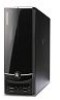
eMachines EL1358G eMachines EL1358 Service Guide
eMachines EL1358G Manual
 |
View all eMachines EL1358G manuals
Add to My Manuals
Save this manual to your list of manuals |
eMachines EL1358G manual content summary:
- eMachines EL1358G | eMachines EL1358 Service Guide - Page 1
eMachines EL1358 Service Guide PRINTED IN TAIWAN - eMachines EL1358G | eMachines EL1358 Service Guide - Page 2
Revision History Refer to the table below for changes made on this version of the EL1358 Desktop Computer Service Guide. Date Chapter Updates ii EL1358 Service Guide - eMachines EL1358G | eMachines EL1358 Service Guide - Page 3
, manual or otherwise, without the prior written permission of Acer Incorporated. Disclaimer The information in this guide is subject to change without notice. Acer Incorporated makes no representations or warranties, either expressed or implied, with respect to the contents hereof and specifically - eMachines EL1358G | eMachines EL1358 Service Guide - Page 4
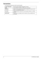
topic. Alerts you to any physical risk or system damage that might result from doing or not doing specific actions. Gives precautionary measures to avoid possible hardware or software problems. Reminds you to do specific actions relevant to the accomplishment of procedures. iv EL1358 Service Guide - eMachines EL1358G | eMachines EL1358 Service Guide - Page 5
, your regional office MAY have decided to extend the functionality of a machine (e.g. add-on card, modem, or extra memory capability). These LOCALIZED FEATURES will NOT be covered in this generic service guide. In such cases, please contact your regional offices or the responsible personnel - eMachines EL1358G | eMachines EL1358 Service Guide - Page 6
vi EL1358 Service Guide - eMachines EL1358G | eMachines EL1358 Service Guide - Page 7
Expansion Boards 31 Removing the Memory Modules 32 Removing the Power Supply Unit 32 Removing the Front I/O and Card Reader Assembly 35 Removing the Mainboard 39 Troubleshooting 41 Hardware Diagnostic Procedure 41 System Check Procedures 41 Checkpoints 42 POST Error Indicators 46 BIOS - eMachines EL1358G | eMachines EL1358 Service Guide - Page 8
Table of Contents BIOS 82 Technical Specifications 82 Memory 83 Hard Disk Drive 83 Optical Disc Drive 84 Card Reader 84 Gigabit Ethernet 84 Audio 84 Power Supply Unit 85 Power Management 85 Index ...87 viii - eMachines EL1358G | eMachines EL1358 Service Guide - Page 9
One PCI Express x16 slot (reserved for GPU card installation) • One PCI Express x1 slot • Wired LAN: Realtek RTL8201EL (Single-Chip/Port 10/100/1000 Fast Ethernet PHYceiver with Auto MDIX) • WLAN option: Low-profile PCI-E x1 802.11 b/g/n wireless network adapter and Wireless 802.11b/g/n USB Adapter - eMachines EL1358G | eMachines EL1358 Service Guide - Page 10
ports (two) - Headphone jack - Microphone jack - Card reader • Rear panel - PS/2 keyboard and mouse ports - External display (VGA) port - USB ports (four) - Ethernet jack (RJ45) - Microphone, line-out, and line-in jacks - Kensington lock - Key lock • Power LED • Power button 2 EL1358 Service Guide - eMachines EL1358G | eMachines EL1358 Service Guide - Page 11
Physical Specifications Aspect Chassis dimension (W × D × H) System weight Mainboard form factor Mainboard dimensions (W × H) Description 100 mm (W) X 361.8 mm (D) x 265 mm temperature Operating humidity Description 5 to 35 °C (41 to 95 °F) 15% to 80% RH non-condensing EL1358 Service Guide 3 - eMachines EL1358G | eMachines EL1358 Service Guide - Page 12
and tables in this section illustrate the physical outlook of the computer. Front View No. Component 1 Optical drive eject button 2 Optical drive cover 3 Power button/indicator 4 Microphone-in jack 5 Headphone jack 6 Multi-in-1 card reader 7 USB 2.0 ports 4 EL1358 Service Guide - eMachines EL1358G | eMachines EL1358 Service Guide - Page 13
View No. Component 1 Line-in jack 2 LAN connector 3 Key lock 4 Kensington lock 5 Power connector 6 Fan aperture 7 PS/2 keyboard connector 8 PS/2 mouse connector 9 Monitor port 10 USB 2.0 ports 11 Microphone jack 12 Line-out jack 13 Expansion slots EL1358 Service Guide 5 - eMachines EL1358G | eMachines EL1358 Service Guide - Page 14
6 EL1358 Service Guide - eMachines EL1358G | eMachines EL1358 Service Guide - Page 15
BIOS settings. The Setup Utility loads the configuration values in a battery-backed nonvolatile memory called CMOS RAM. This memory area is not part of the system RAM, which allows configuration data to be retained when power "Setup" or "Setup Utility" in this Service Guide. EL1358 Service Guide 7 - eMachines EL1358G | eMachines EL1358 Service Guide - Page 16
Delete. If you fail to press Delete before POST is completed, you will need to restart the computer. Use the Up/Down/Left/Right arrow keys to move between the menu options, then press Enter to Use the Up/Down/Left/Right arrow keys to scroll through the items in the submenu 8 EL1358 Service Guide - eMachines EL1358G | eMachines EL1358 Service Guide - Page 17
• The screenshots used in this section are for illustration only. The values displayed may not be the same as those in your computer. • In the descriptive tables following each of the menu screen illustrations, settings in boldface are the default and suggested settings. EL1358 Service Guide 9 - eMachines EL1358G | eMachines EL1358 Service Guide - Page 18
installed on the system Speed of the processor installed on the system Size of system memory detected during boot-up Official model name of the computer. System serial number. Current system BIOS version Date when the CMOS setup utility was released. System asset tag number 10 EL1358 Service Guide - eMachines EL1358G | eMachines EL1358 Service Guide - Page 19
the POST. Options include: • All Errors - Any error detected will pause the system. • No Errors - BIOS will ignore any errors detected during POST • All, but Keyboard - If a keyboard error is detected, BIOS will pause the system. All Errors No Errors All, But Keyboard EL1358 Service Guide 11 - eMachines EL1358G | eMachines EL1358 Service Guide - Page 20
Disabled, when anything attempts to access the boot sector or hard disk partition table, there will be no warning message. Select whether to allow the BIOS to emit error beeps or display error messages during USB device enumeration. On Off Enabled Disabled Enabled Disabled 12 EL1358 Service Guide - eMachines EL1358G | eMachines EL1358 Service Guide - Page 21
priority sequence is: PCIE, Onboard, then PCI. When a GPU expansion board is installed, you can select how the system video memory (frame buffer) is allotted. Value Enabled Disabled Enabled Disabled Enabled Disabled Auto PCIE Onboard PCI Auto 32 MB 64 MB 128 MB 256 MB EL1358 Service Guide 13 - eMachines EL1358G | eMachines EL1358 Service Guide - Page 22
controller. Enables or disables the onboard USB controller. Legacy USB Support USB Storage Emulation Enables or disables support for a USB mouse and USB keyboard. When enabled, any attached USB mouse or USB keyboard can control the system even when there is no USB driver loaded onto the system. If - eMachines EL1358G | eMachines EL1358 Service Guide - Page 23
a network message. Enables or disables the system to wake up from a power-saving mode when a PS/2 keyboard or mouse is used. Value S3 (STR) S1 (POS) Enabled Disabled Enabled Disabled Enabled Disabled Enabled Disabled Enabled Disabled Enabled Disabled Enabled Disabled EL1358 Service Guide 15 - eMachines EL1358G | eMachines EL1358 Service Guide - Page 24
PC Health Status Field CPU Temperature System Temperature CPU Fan Speed System Fan Speed CPU Core +1.2V +3.30V +5.00V +12.0V 5VSB VBAT Description Value These items lets you monitor the parameters for critical voltages, temperatures and fan speeds. 16 EL1358 Service Guide - eMachines EL1358G | eMachines EL1358 Service Guide - Page 25
problems with other electronics in the area. Note: Remember to disable the Spread Spectrum feature if you are overclocking. A slight jitter can introduce a temporary boost in clock speed causing the overclocked processor to lock up. Value Enabled Disabled Enabled Disabled EL1358 Service Guide - eMachines EL1358G | eMachines EL1358 Service Guide - Page 26
BIOS Security Features Field Supervisor Password User Password Change Supervisor Password Description Displays the supervisor password status. When set to Installed, this password will allow the user to access and change all settings in the Setup Utility. Displays the user 18 EL1358 Service Guide - eMachines EL1358G | eMachines EL1358 Service Guide - Page 27
is removed, the user password will also be remove. 1. Select Change Supervisor Password or Change User Password, then press Enter Utility. Load Default Settings Execute this menu to load the factory-default settings for all Setup parameters. Keyboard shortcut: F9 Perform EL1358 Service Guide 19 - eMachines EL1358G | eMachines EL1358 Service Guide - Page 28
Exit Without Saving Execute this menu to closes the Setup Utility without making any changes. 20 EL1358 Service Guide - eMachines EL1358G | eMachines EL1358 Service Guide - Page 29
optional card reader slots are empty. 2. Turn off the power to the computer and all peripherals. 3. Unplug the power cord from the computer. 4. Unplug the network cable and all connected peripheral devices from the computer. 5. Place the computer on a flat, steady surface. EL1358 Service Guide 21 - eMachines EL1358G | eMachines EL1358 Service Guide - Page 30
2.5 cm (1.0 in) to release it from the chassis notches, then detach the panel from the chassis. 3. Put the side panel aside for reinstallation later. 22 EL1358 Service Guide - eMachines EL1358G | eMachines EL1358 Service Guide - Page 31
Removing the Front Bezel 1. Release the front bezel retention tabs from the chassis interior. 2. Pull the front bezel away from the chassis. 3. Detach the front bezel. EL1358 Service Guide 23 - eMachines EL1358G | eMachines EL1358 Service Guide - Page 32
sink fan assembly, in an upright position, on top of the optical drive, as shown below, then disconnect the fan cable from the mainboard. 24 EL1358 Service Guide - eMachines EL1358G | eMachines EL1358 Service Guide - Page 33
:If you are going to install a new processor, note the arrow on the corner to make sure the processor is properly oriented over the socket. EL1358 Service Guide 25 - eMachines EL1358G | eMachines EL1358 Service Guide - Page 34
Removing the HDD-ODD Bracket 1. Remove the two screws that secure the HDD-ODD bracket to the chassis. 2. Lift the bracket up. 26 EL1358 Service Guide - eMachines EL1358G | eMachines EL1358 Service Guide - Page 35
Removing the Optical Drive and the Hard Disk Drive 1. Disconnect the SATA and power cables from the rear of the optical drive. 2. Disconnect the other end of the SATA cable from the mainboard. EL1358 Service Guide 27 - eMachines EL1358G | eMachines EL1358 Service Guide - Page 36
3. Disconnect the SATA and power cables from the rear of the hard disk drive. 4. Disconnect the other end of the SATA cable from the mainboard. 28 EL1358 Service Guide - eMachines EL1358G | eMachines EL1358 Service Guide - Page 37
5. Remove the screws that secure the optical drive to the HDD-ODD bracket. 6. Pull the optical drive out of the drive bay. EL1358 Service Guide 29 - eMachines EL1358G | eMachines EL1358 Service Guide - Page 38
7. Remove the four screws that secure the hard disk drive to the HDD bracket. 8. Slide the hard disk drive out of the bracket. 30 EL1358 Service Guide - eMachines EL1358G | eMachines EL1358 Service Guide - Page 39
pull up the expansion board (1), move it slightly to the left and remove (2) from the slot. 3. Remove the screw from the expansion board bracket opposite the PCIEX2 slot. 4. Gently pull up the expansion board (1), move it slightly to the left and remove (2) from the slot. EL1358 Service Guide 31 - eMachines EL1358G | eMachines EL1358 Service Guide - Page 40
Removing the Power Supply Unit 1. Disconnect the 4-pin and the 24-pin ATX power supply cables from its mainboard connector. a. Squeeze on the retaining latch (a) attached to the cable end of the connector. b. Grasp the cable end of the connector and pull it straight up (b). 32 EL1358 Service Guide - eMachines EL1358G | eMachines EL1358 Service Guide - Page 41
2. Remove the screw that secures the power supply to the chassis. 3. Remove the two screws that secure the power supply to the rear panel. EL1358 Service Guide 33 - eMachines EL1358G | eMachines EL1358 Service Guide - Page 42
4. Push the power supply module toward the front. 5. Tilt the power supply module slightly to the right and lift it out of the chassis. 34 EL1358 Service Guide - eMachines EL1358G | eMachines EL1358 Service Guide - Page 43
Removing the Front I/O and Card Reader Assembly 1. Disconnect the power button/LED, front I/O and card reader cables from their mainboard connectors. 2. Open the plastic clip (1) and release the cables from the metal clip (2) in the direction indicated. EL1358 Service Guide 35 - eMachines EL1358G | eMachines EL1358 Service Guide - Page 44
3. Detach the cables from the card. Remove the cables. 4. Remove the screw that secures the bracket to the chassis. 36 EL1358 Service Guide - eMachines EL1358G | eMachines EL1358 Service Guide - Page 45
5. Pull the bracket out from the chassis. 6. Remove the two screws that secure the front I/O and card reader assembly to the bracket. EL1358 Service Guide 37 - eMachines EL1358G | eMachines EL1358 Service Guide - Page 46
7. Remove the front I/O and card reader assembly from the bracket. 38 EL1358 Service Guide - eMachines EL1358G | eMachines EL1358 Service Guide - Page 47
Removing the Mainboard 1. Remove the four screws that secure the mainboard to the chassis. Note:Circuit boards >10 cm2 has been highlighted with the yellow rectangle as above image shows. Please detach the Circuit boards and follow local regulations for disposal. EL1358 Service Guide 39 - eMachines EL1358G | eMachines EL1358 Service Guide - Page 48
2. Lift the board from the chassis. 3. Remove the RTC battery. Note:RTC battery has been highlighted with the yellow circle as above image shows. Please detach the RTC battery and follow local regulations for disposal. 40 EL1358 Service Guide - eMachines EL1358G | eMachines EL1358 Service Guide - Page 49
slots on the rear panel are not blocked. 3. Make sure that there is no point of contact in the system that can cause a power short. If the cause of the failure is still can not be determined, perform the "System Internal Inspection" procedure described on the next page. EL1358 Service Guide - eMachines EL1358G | eMachines EL1358 Service Guide - Page 50
Unplug the power cord from the computer. 3. Unplug the network cable and all connected peripheral devices from the computer. 4. Place the computer on a flat, steady surface. 5. Remove the side panel as described in page 22. 6. Verify that the processor, memory module(s), and expansion board(s) are - eMachines EL1358G | eMachines EL1358 Service Guide - Page 51
file size does not equal the found flash part size. Erase the flash part. Program the flash part. The flash has been updated successfully. Make flash write disabled. Disable ATAPI hardware. Restore CPUID value back into register. Give control to F000 ROM at F000:FFF0h. EL1358 Service Guide 43 - eMachines EL1358G | eMachines EL1358 Service Guide - Page 52
section for more information. USB controllers are initialized at this point. Initializes DMAC-1 & DMAC-2. Initialize RTC date/time. Test for total memory installed in the system. Also, Check for DEL or ESC keys to limit memory test. Display total memory in the system. 44 EL1358 Service Guide - eMachines EL1358G | eMachines EL1358 Service Guide - Page 53
devices (Parallel ports, serial ports, and coprocessor in CPU, ... etc.) successfully installed in the system and update the BDA, EBDA...etc. Programming the memory hole or any kind of implementation that needs an adjustment in system RAM size if needed. Updates CMOS memory size from memory found in - eMachines EL1358G | eMachines EL1358 Service Guide - Page 54
0 disables all device nodes, PCI devices, and PnP ISA cards. It also assigns PCI bus numbers. Function 1 initializes all static devices that include manual configured onboard peripherals, memory and I/O decode windows in PCI-PCI bridges, and noncompliant PCI devices. Static resources are also - eMachines EL1358G | eMachines EL1358 Service Guide - Page 55
Gate20 Error Multi-Bit ECC Error Parity Error RAM R/W test failed CMOS Memory Size Wrong Description The BIOS is unable to properly control the mainboard's Gate A20 function, which controls access of memory over 1 MB. This may indicate a problem with the mainboard. This message will only occur - eMachines EL1358G | eMachines EL1358 Service Guide - Page 56
POST. The IDE/ATAPI device configured as Master in the 3rd IDE controller failed an ATAPI compatibility test. This message is typically displayed when the BIOS is trying to detect and configure IDE/ATAPI devices in POST. 48 EL1358 Service Guide - eMachines EL1358G | eMachines EL1358 Service Guide - Page 57
the BIOS is disk. A S.M.A.R.T. capable hard disk sends this message when it detects an imminent failure. This message can be reported by an ATAPI device using the S.M.A.R.T. error reporting standard. S.M.A.R.T. failure messages may indicate the need to replace the hard disk. EL1358 Service Guide - eMachines EL1358G | eMachines EL1358 Service Guide - Page 58
failed to pass the Refresh Retrace Test. BIOS POST could not initialize the Master Interrupt Controller. This may indicate a problem with system hardware. BIOS POST could not initialize the Slave Interrupt Controller. This may indicate a problem with system hardware. 50 EL1358 Service Guide - eMachines EL1358G | eMachines EL1358 Service Guide - Page 59
. Keyboard controller failure. This may indicate a problem with system hardware. PS/2 keyboard is locked. User needs to unlock the keyboard to continue the BIOS POST. The system has been halted. A reset or power cycle is required to reboot the machine. This message appears after a fatal error has - eMachines EL1358G | eMachines EL1358 Service Guide - Page 60
CD. Blinking cursor only; system does not work. • IDE drive connection/cables • IDE disk drives • See "Undetermined Problems". • Mainboard NOTE Ensure the memory modules are installed properly and the contact leads are clean before diagnosing any system problems. 52 EL1358 Service Guide - eMachines EL1358G | eMachines EL1358 Service Guide - Page 61
up the sound volume. • Speaker power/connection/cable. • CD/DVD-ROM drive. NOTE Make sure the optical disc drive is configured correctly in CMOS Setup, the cable/jumper are set correctly and the drive's optical lens is clean before diagnosing any optical drive problems. EL1358 Service Guide 53 - eMachines EL1358G | eMachines EL1358 Service Guide - Page 62
sound feature works normally.) Action/FRU • For an external modem, make sure Power on By Ring in BIOS Setup or Power Management is set to Enabled. For the PCI modem, make sure Wake up by PCI card is set to Enabled. • If a PCI modem card is used, reinsert the modem card to the PCI slot firmly or - eMachines EL1358G | eMachines EL1358 Service Guide - Page 63
the power override switch (located at the back of the computer, just above the connector for the power cable) is not set to OFF. • Power switch cable assembly. • Enter CMOS Setup and load the default settings. • Reload software from Recovery CD. • Power supply • Mainboard EL1358 Service Guide 55 - eMachines EL1358G | eMachines EL1358 Service Guide - Page 64
video card is not working, its memory is not accessible, or its BIOS may be corrupt. • Something is wrong with the mainboard. BIOS damaged. Processor jump to boot block to execute the default procedure. CMOS checksum error Undetermined Problems NOTE • Verify that all attached devices are supported - eMachines EL1358G | eMachines EL1358 Service Guide - Page 65
will be cleared during the creation of the crisis disk. 2. Set up a computer running the Windows XP or Windows Vista operating system and plug in the USB storage device into an available USB port. 3. Copy the target BIOS ROM file to the USB storage device and rename it as "amiboot.rom". 4. Unplug - eMachines EL1358G | eMachines EL1358 Service Guide - Page 66
the system BIOS. 5. Reboot the computer. 6. Press Delete to run the CMOS Setup Utility. 7. Press F9 to load the system default settings. 8. Select Ok, then press Enter. 9. Press F9 to save the default settings and close the Setup utility. 10. Select Ok, then press Enter. 58 EL1358 Service Guide - eMachines EL1358G | eMachines EL1358 Service Guide - Page 67
the power button to turn on the computer. 2. Click Start | Command Prompt | Run as administrator. 3. Perform the steps below if your computer is running 32-bit Windows. a. Key in 'cd wintool\32'. (Go to BIOS path like "D:\WinTool\32") b. Key in 'flash1M.bat' or 'flash1M'. EL1358 Service Guide 59 - eMachines EL1358G | eMachines EL1358 Service Guide - Page 68
c. Press Enter to flash the system BIOS. 4. Perform the steps below if your computer is running 64-bit Windows. a. Key in 'cd wintool\64'. (Go to BIOS path like "D:\WinTool\64") b. Key in 'flash1M.bat' or 'flash1M'. 60 EL1358 Service Guide - eMachines EL1358G | eMachines EL1358 Service Guide - Page 69
the system BIOS. 5. Reboot the computer. 6. Press Delete to run the CMOS Setup Utility. 7. Press F9 to load the system default settings. 8. Select Ok, then press Enter. 9. Press F9 to save the default settings and close the Setup utility. 10. Select Ok, then press Enter. EL1358 Service Guide 61 - eMachines EL1358G | eMachines EL1358 Service Guide - Page 70
all peripherals. 2. Unplug the power cord from the computer. 3. Unplug the network cable and all connected peripheral devices from the computer. 4. Place the computer on a flat, steady surface. 5. Remove the side panel. 6. If necessary, remove any expansion cards, assemblies or cables that prevent - eMachines EL1358G | eMachines EL1358 Service Guide - Page 71
System Architecture This chapter shows the system block diagram and board layout. Block Diagram The core subsystems of the computer are depicted in the following block diagram. Chapter 5 EL1358 Service Guide 63 - eMachines EL1358G | eMachines EL1358 Service Guide - Page 72
9 USBF 2-3 10 USBF 1 11 AUDIOF1 Description CPU socket CPU cooling fan connector DDR3 240-pin slots ITE 8758 Standard 24-pin power connector Serial ATA connectors 12-pin DEBUG port 12-pin power cable header Front panel USB header Front panel card reader header Front panel audio jack header No - eMachines EL1358G | eMachines EL1358 Service Guide - Page 73
Jumper Setting This section explains how to set the jumper for correct configuration of the main board. Jumpers with more than one pin are numbered. When setting a jumper, ensure that 1-2: Close (default) 2-3: Open Before clearing the CMOS, make sure to turn off the system. EL1358 Service Guide 65 - eMachines EL1358G | eMachines EL1358 Service Guide - Page 74
Header Name Function CPU FAN HEADER Definition 1: GND 2: +12V 3: SENSE 4: PWM CONTROL FRONT PANEL HEADER FRONT USB HEADER FRONT USB HEADER FRONT KEY 10: GND 1: PORT-F_L 2: AUGND 3: PORT-F_R 4: FRONT_AUD_DET 5: PORT-E_R 6: MIC2_JD 7: AUGND 8: KEY 9: PORT-E_L 10: LINE2_JD 66 EL1358 Service Guide - eMachines EL1358G | eMachines EL1358 Service Guide - Page 75
17:GND 6:VCC 18:GND 7:GND 19:GND 8:ATX_PWRGD 20:NC 9:5VSB 21VCC 10:+12V 22:VCC 11:+12V 23:VCC 12:VCC3 24:GND EL1358 Service Guide 67 - eMachines EL1358G | eMachines EL1358 Service Guide - Page 76
following for information on connecting the main board's optional devices: SATA1~2: Serial ATA connectors These connectors are used to support the new Serial ATA devices for the highest datatransfer rates (3.0 Gb/s), simpler disk drive cabling and easier PC assembly. It elimi-nates limitations of - eMachines EL1358G | eMachines EL1358 Service Guide - Page 77
- 5 USB_FP_P0+ 6 USB_FP_P1+ 7 GND 8 GND 9 Key 10 USB_FP_OC0 Function Front Panel USB Power Front Panel USB Power USB Port 0 Negative Signal USB Port 1 Negative Signal USB Port 0 Positive Signal USB Port 1 Positive Signal Ground Ground No pin Overcurrent signal EL1358 Service Guide 69 - eMachines EL1358G | eMachines EL1358 Service Guide - Page 78
to PWR2. 3. Connect the case switches and indicator LEDs to the LEDH1. 4. Connect the auxiliary case power supply connector to PWR1. CPUFAN1: CPU Cooling Fan Power Connector Pin Signal Name 1 GND 2 +12V 3 Sense 4 PWM Function System ground Power +12V Sensor PWM 70 EL1358 Service Guide - eMachines EL1358G | eMachines EL1358 Service Guide - Page 79
Pin Signal Name 1 VCC Reset Switch (+) 2 GLED0 3 HDD_LEDN Hard disk LED (-) 4 GLED1 5 GND Reset Switch (-) 6 PWRSW 7 HWRST_L 14 F_LAN_LED Function *MSG LED (+) *MSG LED (-) Power Switch (+) Power Switch (-) No pin Reset Switch (+) Reset Switch (+) EL1358 Service Guide 71 - eMachines EL1358G | eMachines EL1358 Service Guide - Page 80
72 EL1358 Service Guide - eMachines EL1358G | eMachines EL1358 Service Guide - Page 81
printed Service Guide. You MUST use the local FRU list provided by your regional Acer office to order FRU parts for service. NOTE Follow the local government regulations, or the rules set by your regional office on how to return or dispose of defective parts. Exploded Diagram EL1358 Service Guide - eMachines EL1358G | eMachines EL1358 Service Guide - Page 82
IO BOARD USB 2.0 2 USB PORT 2 AUDIO PORT W/ O CARD READER Description F-IO BD USB 2.0 2 USB PORT 2 AUDIO PORT OEM Part No. 55.NCM01.001 CABLES 74 FRONT IO & CARD READER BOARD USB 2.0 2 USB PORT 2 AUDIO PORT VGA CARD PC PARTNER RADEON HD4350 512MB DDR2 32BITS HYNIX H5PS1G63EFR-20R DVI HDMI VGA - eMachines EL1358G | eMachines EL1358 Service Guide - Page 83
POWER CORD 250V 3PIN INDIA POWER CORD 1800MM BLACK S.AFRAICA POWER CORD 250V 3PIN BRAZIL POWER CORD 230V DENMARK POWER CORD 16A 250V 1800MM ISRAEL BLACK POWER CORD 125V 7A 3G JAPAN POWER CORD 125V 10A BLACK MEXICO POWER CORD 250V 3PIN 1830MM BLACK THAILAND POWER 60.NCM01.002 EL1358 Service Guide 75 - eMachines EL1358G | eMachines EL1358 Service Guide - Page 84
60.NCM01.003 ASSEMBLY FRONT BEZEL FOR NONE CARD READER CRT COVER ASSY MAIN-BEZEL B CPU ATHLON II X2 260 3.2G 2M AM3 65W KC.A2M02.260 IC CPU ATHLONII 235E AM3+ 2.7G KC.AE202.235 IC CPU ATHLON II X2 240E 2.8G KC.AE202.240 IC CPU ATHLON II X3 400E 2.2GH KC.AE202.400 76 EL1358 Service Guide - eMachines EL1358G | eMachines EL1358 Service Guide - Page 85
Category CPU/PROCESSOR EL1358 Service Guide Part Name CPU AMD ATHLON II X3 405E 2.3GHZ 1.5M L2 CACHE 45W RANA ATHIIX3405E CPU AMD ATHLONII 170U AM3+ 2.0G 1M 3600 940 20W C-3 SINGLE CORE CPU AMD ATHLONII 220 AM3+ 2.8G 2X512K 4000 940 65W C-3 DUAL CORE CPU AMD ATHLONII 250 AM3+ 3.0G 2X1M 4000 940 65W - eMachines EL1358G | eMachines EL1358 Service Guide - Page 86
HDD/HARD DISK DRIVE Part Name CPU AMD SEMPRON 145 AM3+ 2.8G 512K 4000 940 45W C-3 DVD-RW PLDS SUPER-MULTI DRIVE HH LABELFLASH 16X GH41F LF+HF BLACK BEZEL SATA + WIN 7 ODD HLDS SUPER-MULTI DRIVE HH 16X GH41N BLACK BEZEL SATA .50007.012 KH.50001.022 KH.50008.022 KH.64007.002 78 EL1358 Service Guide - eMachines EL1358G | eMachines EL1358 Service Guide - Page 87
.A73C1.G02 DDR3 1333MHZ KN.1GB01.031 KN.1GB03.032 KN.1GB0B.030 KN.1GB0B.036 KN.1GB0G.024 KN.1GB0H.015 KN.2GB01.025 EL1358 Service Guide 79 - eMachines EL1358G | eMachines EL1358 Service Guide - Page 88
MEMORY POINTING DEVICE POWER SUPPLY 80 Part Name MEMORY NANYA DDR3 1333MHZ 2G NT2GC64B8HA0NF-CG MEMORY KINGSTON DDR3 1333MHZ 2G UNB ACR256X64D3U1333C9 MEMORY SAMSUNG DDR3 1333MHZ 2G M378B5673EH1CH9 MEMORY SAMSUNG DDR3 1333MHZ 2G M378B5673FH0CH9 MEMORY HYNIX DDR3 1333MHZ 2G HMT125U6BFR8C-H9 MEMORY - eMachines EL1358G | eMachines EL1358 Service Guide - Page 89
SCREW FLAT #6-32*3/ 16 NI SPEAKER ASI USB 2.0 Q4-08 USB SPK USB NEO 2003B WITH BLACK OEM Part No. PY.2200B.010 PY.2200F.001 PY.2200F.005 86.00J07.B60 86.00J44.C60 86.00N03.B40 86.00J90.B60 86.1A324.5R0 86.5A5B6.012 SP.10600.019 SP.10600.032 EL1358 Service Guide 81 - eMachines EL1358G | eMachines EL1358 Service Guide - Page 90
Model No. of cores Base frequency L2 cache DDR3 speed support Thermal design power Specification Athlon™ II X2 250e/245e/ 240e 2 3.0/2.9/2.8 GHz Specification • NVIDIA® nForce® 430 MCP (MCP61), BIOS Item BIOS chip Setup utility Specification AMI BIOS CMOS Setup Utility EL1358 Service Guide - eMachines EL1358G | eMachines EL1358 Service Guide - Page 91
slot Maximum memory Data rate Supported capacities DIMM type Supported brands Population rule Specification memory modules in any combination as long as they match the above specifications. Hard Disk Drive Item Controller Number of HDD bays Form factor Interface Supported 83 EL1358 Service Guide - eMachines EL1358G | eMachines EL1358 Service Guide - Page 92
- DH-16D5SH • PLDS - DH-16ABSH Card Reader Item Controller Card compatibility Specification Multi-in-1 • Memory Stick (MS) - supports up to 32 GB • xD-Picture Card (xD) - supports up to 2 GB • Secure Digital (SD) - supports up to 2 TB • MultiMedia Card (MMC) - supports up to 32 GB • Reduced-Size - eMachines EL1358G | eMachines EL1358 Service Guide - Page 93
connector • 1 x 4-pin ATX connector • 2 x SATA connectors Power Management Devices Power Button USB Keyboard/Mouse PME RCT WOR S1 V V Disabled Disabled Disabled S3 V V Disabled Disabled Disabled S4 V N/A Disabled Disabled Disabled S5 V N/A Disabled Disabled Disabled 85 EL1358 Service Guide - eMachines EL1358G | eMachines EL1358 Service Guide - Page 94
EL1358 Service Guide 86 - eMachines EL1358G | eMachines EL1358 Service Guide - Page 95
card reader assembly 35 expansion board 31 front bezel 23 front I/O assembly 35 hard disk drive 27 HDD-ODD bracket 26 mainboard 39 memory 32 optical disc drive 27 power supply unit 32 side panel 22 tools 21 E environmental requirements 3 Ethernet port specifications 84 expansion slots expansion - eMachines EL1358G | eMachines EL1358 Service Guide - Page 96
specifications 82 troubleshooting 52 PSU, see power supply unit 32 R Return Merchandise Authorization 73 RMA, see Return Merchandise Authorization 73 RTC battery BIOS error 7 RTC clock troubleshooting 54 S Save & Exit Setup 19 side panel remove 22 slots expansion 5 software specifications antivirus - eMachines EL1358G | eMachines EL1358 Service Guide - Page 97
3 troubleshooting BIOS checkpoints 42 BIOS recovery 57 BIOS update 58 clearing CMOS 62 component failure 52 hardware diagnostic procedure 41 POST error indicators 46 U undetermined problems 56 USB ports bootable device 14 front 4, 5 legacy device 14 user password 18 V VGA port 5 video controller - eMachines EL1358G | eMachines EL1358 Service Guide - Page 98
90
-
 1
1 -
 2
2 -
 3
3 -
 4
4 -
 5
5 -
 6
6 -
 7
7 -
8
-
9
-
10
-
11
-
12
-
13
-
14
-
15
-
16
-
17
-
18
-
19
-
20
-
21
-
22
-
23
-
24
-
25
-
26
-
27
-
28
-
29
-
30
-
31
-
32
-
33
-
34
-
35
-
36
-
37
-
38
-
39
-
40
-
41
-
42
-
43
-
44
-
45
-
46
-
47
-
48
-
49
-
50
-
51
-
52
-
53
-
54
-
55
-
56
-
57
-
58
-
59
-
60
-
61
-
62
-
63
-
64
-
65
-
66
-
67
-
68
-
69
-
70
-
71
-
72
-
73
-
74
-
75
-
76
-
77
-
78
-
79
-
80
-
81
-
82
-
83
-
84
-
85
-
86
-
87
-
88
-
89
-
90
-
91
-
92
-
93
-
94
-
95
-
96
-
97
-
98
 |
 |

eMachines
EL1358
Service Guide
PRINTED IN TAIWAN