2014 Ducati Hypermotard Hyperstrada Owners Manual - Page 223
2014 Ducati Hypermotard Hyperstrada Manual

Page 223 highlights
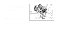
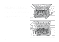
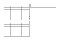
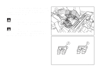
Electrical system Basic electric items are:. Headlight with: low/high beams: bulb H4 blue vision (12V - 60/55W); parking light: no. 8 LEDs; Electrical controls on handlebars. Turn indicators: front: bulb type GE 2641A 12VRY10W; rear: bulb type GE 2641A 12VRY10W. Horn. Brake light switches. Battery , 12V-10 Ah, dry. GENERATOR 14V-490W. ELECTRONIC VOLTAGE REGULATOR, protected with a 30 A fuse located close to the rear fuse box (C, Fig 167). Starter motor: 12V-0.7 kW. Tail light: parking light: 6 LEDs (0.27W -13.5V); stop light: 6 LEDs (2.43W-13.5V). Number plate light: bulb: C5W (12-5W). Note For bulb replacement instructions, please read "Replacing the high and low beam bulbs". Fuses There are thirteen fuses that protect the electric components, located inside the front and rear fuse boxes, and one on the electric solenoid starter. There is a spare fuse in every box. Refer to the table below to identify the circuits protected by the various fuses and their ratings. 221
-
 1
1 -
2
-
3
-
4
-
5
-
6
-
7
-
8
-
9
-
10
-
11
-
12
-
13
-
14
-
15
-
16
-
17
-
18
-
19
-
20
-
21
-
22
-
23
-
24
-
25
-
26
-
27
-
28
-
29
-
30
-
31
-
32
-
33
-
34
-
35
-
36
-
37
-
38
-
39
-
40
-
41
-
42
-
43
-
44
-
45
-
46
-
47
-
48
-
49
-
50
-
51
-
52
-
53
-
54
-
55
-
56
-
57
-
58
-
59
-
60
-
61
-
62
-
63
-
64
-
65
-
66
-
67
-
68
-
69
-
70
-
71
-
72
-
73
-
74
-
75
-
76
-
77
-
78
-
79
-
80
-
81
-
82
-
83
-
84
-
85
-
86
-
87
-
88
-
89
-
90
-
91
-
92
-
93
-
94
-
95
-
96
-
97
-
98
-
99
-
100
-
101
-
102
-
103
-
104
-
105
-
106
-
107
-
108
-
109
-
110
-
111
-
112
-
113
-
114
-
115
-
116
-
117
-
118
-
119
-
120
-
121
-
122
-
123
-
124
-
125
-
126
-
127
-
128
-
129
-
130
-
131
-
132
-
133
-
134
-
135
-
136
-
137
-
138
-
139
-
140
-
141
-
142
-
143
-
144
-
145
-
146
-
147
-
148
-
149
-
150
-
151
-
152
-
153
-
154
-
155
-
156
-
157
-
158
-
159
-
160
-
161
-
162
-
163
-
164
-
165
-
166
-
167
-
168
-
169
-
170
-
171
-
172
-
173
-
174
-
175
-
176
-
177
-
178
-
179
-
180
-
181
-
182
-
183
-
184
-
185
-
186
-
187
-
188
-
189
-
190
-
191
-
192
-
193
-
194
-
195
-
196
-
197
-
198
-
199
-
200
-
201
-
202
-
203
-
204
-
205
-
206
-
207
-
208
-
209
-
210
-
211
-
212
-
213
-
214
-
215
-
216
-
217
-
 218
218 -
 219
219 -
 220
220 -
 221
221 -
 222
222 -
 223
223 -
 224
224 -
 225
225 -
 226
226 -
 227
227 -
 228
228 -
229
-
230
-
231
-
232
 |
 |