ASRock 4Core1333-GLAN R2.0 User Manual
ASRock 4Core1333-GLAN R2.0 Manual
 |
View all ASRock 4Core1333-GLAN R2.0 manuals
Add to My Manuals
Save this manual to your list of manuals |
ASRock 4Core1333-GLAN R2.0 manual content summary:
- ASRock 4Core1333-GLAN R2.0 | User Manual - Page 1
4Core1333-GLAN User Manual Version 2.0 Published January 2008 Copyright©2008 ASRock INC. All rights reserved. 1 - ASRock 4Core1333-GLAN R2.0 | User Manual - Page 2
of ASRock Inc. Products and corporate names appearing in this manual may or may not be registered trademarks or copyrights of their advised of the possibility of such damages arising from any defect or error in the manual or product. This device complies with Part 15 of the FCC Rules. Operation is - ASRock 4Core1333-GLAN R2.0 | User Manual - Page 3
16 2.6 Expansion Slots (PCI and PCI Express Slots 18 2.7 Jumpers Setup 19 2.8 Onboard Headers and Connectors 20 2.9 HDMI_SPDIF Header Connection Guide 24 2.10 SATAII Hard Disk Setup Guide 25 2.11 Serial ATA (SATA) / Serial ATAII (SATAII) Hard Disks Installation 26 2.12 Driver Installation - ASRock 4Core1333-GLAN R2.0 | User Manual - Page 4
3.6 Security Screen 41 3.7 Exit Screen 42 4 Software Support 43 4.1 Install Operating System 43 4.2 Support CD Information 43 4.2.1 Running Support CD 43 4.2.2 Drivers Menu 43 4.2.3 Utilities Menu 43 4.2.4 Contact Information 43 4 - ASRock 4Core1333-GLAN R2.0 | User Manual - Page 5
to the hardware installation. Chapter 3 and 4 contain the configuration guide to BIOS setup and information of the Support CD. Because the motherboard specifications and the BIOS software might be updated, the content of this manual will be subject to change without notice. In case any modifications - ASRock 4Core1333-GLAN R2.0 | User Manual - Page 6
Northbridge: Intel® P31/G31 - Southbridge: Intel® ICH7 - Dual Channel DDR2 Memory Technology (see CAUTION 3) - 4 x DDR2 DIMM slots (see CAUTION 4) - Support DDR2 800/667 (see CAUTION 5) - Max. capacity: 4GB (see CAUTION 6) - CPU Frequency Stepless Control (see CAUTION 7) - ASRock U-COP (see CAUTION - ASRock 4Core1333-GLAN R2.0 | User Manual - Page 7
2 USB 2.0 ports) (see CAUTION 10) - 4Mb AMI BIOS - AMI Legal BIOS - Supports "Plug and Play" - ACPI 1.1 Compliance Wake Up Events - Supports jumperfree - AMBIOS 2.3.1 Support - Drivers, Utilities, AntiVirus Software (Trial Version) - CPU Temperature Sensing - Chassis Temperature Sensing - CPU - ASRock 4Core1333-GLAN R2.0 | User Manual - Page 8
read "Untied Overclocking Technology" on page 26 for details. 3. This motherboard supports Dual Channel Memory Technology. Before you implement Dual Channel Memory Technology, make sure to read the installation guide of memory modules on page 16 for proper installation. 4. There are memory - ASRock 4Core1333-GLAN R2.0 | User Manual - Page 9
1.3 Minimum Hardware Requirement Table for Windows® VistaTM Premium 2007 and Basic Logo For system integrators and users who purchase this motherboard and plan to submit Windows® VistaTM Premium 2007 and Basic logo, please follow below table for minimum hardware requirements. CPU Memory VGA - ASRock 4Core1333-GLAN R2.0 | User Manual - Page 10
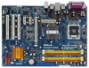
1.4 Motherboard Layout 1 2 34 56 PS2 Keyboard 1 PS2 Mouse PS2_USB_PWR1 ATX12V1 21.8cm (8.6 in) CPU_FAN1 78 PARALLEL PORT DDRII_4 (64/72 bit, 240-pin module) DDRII_3 (64/72 bit, 240-pin module) DDRII_2 (64/72 bit, 240-pin module) DDRII_1 (64/72 bit, 240-pin module) Quad Core CPU DDR2 - ASRock 4Core1333-GLAN R2.0 | User Manual - Page 11
1 . 5 ASRock HD 6CH I/O Panel 1 11 10 9 1 Parallel Port 2 RJ-45 Port 3 Line In (Light Blue) 4 Front Speaker (Lime) 5 Microphone (Pink) 6 USB 2.0 Ports (USB45) 2 3 4 5 8 7 6 7 USB 2.0 Ports (USB01) 8 USB 2.0 Ports (USB23) 9 Serial Port: COM1 10 PS/2 Keyboard Port (Purple) 11 PS/2 Mouse Port - ASRock 4Core1333-GLAN R2.0 | User Manual - Page 12
Chapter 2 Installation 4Core1333-GLAN is an ATX form factor (12.0" x 8.6", 30.5 x 21.8 cm) motherboard. Before you install the motherboard, study the configuration of your chassis to ensure that the motherboard fits into it. Make sure to unplug the power cord before installing or removing the - ASRock 4Core1333-GLAN R2.0 | User Manual - Page 13
2.3 CPU Installation For the installation of Intel 775-LAND CPU, please follow the steps below. 775-Pin Socket Overview Before you insert the 775-LAND CPU into the socket, please check if the CPU surface is unclean or if there is any bent pin on the socket. Do not force to insert the CPU into the - ASRock 4Core1333-GLAN R2.0 | User Manual - Page 14
Pick and Place Cap): Use your left hand index finger and thumb to support the load plate edge, engage PnP cap with right hand thumb and peel the PnP cap. 2. This cap must be placed if returning the motherboard for after service. Step 4. Close the socket: Step 4-1. Rotate the load plate onto the IHS. - ASRock 4Core1333-GLAN R2.0 | User Manual - Page 15
Heatsink This motherboard is equipped with 775-Pin socket that supports Intel 775-LAND CPU. Please adopt the type of , see page 10, No. 6). For proper installation, please kindly refer to the instruction manuals of your CPU fan and heatsink. Below is an example to illustrate the installation of - ASRock 4Core1333-GLAN R2.0 | User Manual - Page 16
2.5 Installation of Memory Modules (DIMM) 4Core1333-GLAN motherboard provides four 240-pin DDR2 (Double Data Rate 2) DIMM slots, and supports Dual Channel Memory Technology. For dual channel configuration, you always need to install identical (the same brand, speed, size and chip-type) DDR2 DIMM - ASRock 4Core1333-GLAN R2.0 | User Manual - Page 17
Recommended Memory Configurations (DS: Double Side, SS: Single Side) DDRII_1 DDRII_2 DDRII_3 DDRII_4 (Yellow Slot) (Orange Slot) (Yellow Slot) (Orange Slot) 1 memory module DS/SS* X X X 2 memory modules DS/SS X DS/SS X 2 memory modules X DS/SS X DS/SS 3 memory modules SS SS DS/SS - ASRock 4Core1333-GLAN R2.0 | User Manual - Page 18
2.6 Expansion Slots (PCI and PCI Express Slots) There are 3 PCI slots and 3 PCI Express slots on this motherboard. PCI slots: PCI slots are used to install expansion cards that have the 32-bit PCI interface. PCIE slots: PCIE1 (PCIE x16 slot) is used for PCI Express cards with x16 lane width graphics - ASRock 4Core1333-GLAN R2.0 | User Manual - Page 19
2.7 Jumpers Setup The illustration shows how jumpers are setup. When the jumper cap is placed on pins, the jumper is "Short". If no jumper cap is placed on pins, the jumper is "Open". The il- lustration shows a 3-pin jumper whose pin1 and pin2 are "Short" when jumper cap is placed on these 2 - ASRock 4Core1333-GLAN R2.0 | User Manual - Page 20
80-conductor ATA 66/100 cable Note: Please refer to the instruction of your IDE device vendor for the details. Serial ATAII Connectors (Port1) SATAII_3 (Port2) These four Serial ATAII (SATAII) connectors support SATA data cables for internal storage devices. The current SATAII interface allows - ASRock 4Core1333-GLAN R2.0 | User Manual - Page 21
allows convenient connection and control of audio devices. 1. High Definition Audio supports Jack Sensing, but the panel wire on the chassis must support HDA to function correctly. Please follow the instruction in our manual and chassis manual to install your system. 2. If you use AC'97 audio panel - ASRock 4Core1333-GLAN R2.0 | User Manual - Page 22
connect a CPU fan cable to this connector and match the black wire to the ground pin. Though this motherboard provides 4-Pin CPU fan (Quiet Fan) support, the 3-Pin CPU fan still can work successfully even without the fan speed control function. If you plan to connect the 3-Pin CPU fan to - ASRock 4Core1333-GLAN R2.0 | User Manual - Page 23
ATX Power Connector (24-pin ATXPWR1) (see p.10, No. 3) 13 1 Please connect an ATX power supply to this connector. 24 12 Though this motherboard provides 24-pin ATX power connector, 13 1 it can still work if you adopt a traditional 20-pin ATX power supply. To use the 20-pin ATX power supply, - ASRock 4Core1333-GLAN R2.0 | User Manual - Page 24
. For the proper installation of HDMI VGA card, please refer to the installation guide on page 18. Step 2. Connect the black end (A) of HDMI_SPDIF cable to the of PCI Express VGA card. Please refer to the VGA card user manual for connector usage in advance. Connect the HDMI output connector on HDMI - ASRock 4Core1333-GLAN R2.0 | User Manual - Page 25
guide. Some default setting of SATAII hard disks may not be at SATAII mode, which operate with the best performance. In order to enable SATAII function, please follow the below instruction 's website for details: http://www.hitachigst.com/hdd/support/download.htm The above examples are just for your - ASRock 4Core1333-GLAN R2.0 | User Manual - Page 26
. STEP 4: Connect the other end of the SATA data cable to the SATA / SATAII hard disk. 2.12 Driver Installation Guide To install the drivers to your system, please insert the support CD to your optical drive first. Then, the drivers compatible to your system can be auto-detected and listed on the - ASRock 4Core1333-GLAN R2.0 | User Manual - Page 27
Chapter 3 BIOS SETUP UTILITY 3.1 Introduction This section explains how to use the BIOS SETUP UTILITY to configure your system. The BIOS FWH chip on the motherboard stores the BIOS SETUP UTILITY. You may run the BIOS SETUP UTILITY when you start up the computer. Please press during the Power-On - ASRock 4Core1333-GLAN R2.0 | User Manual - Page 28
3.1.2 Navigation Keys Please check the following table for the function description of each navigation key. Navigation Key(s) / / + / Function Description Moves cursor left or right to select Screens Moves cursor up or down to select items To change option for the - ASRock 4Core1333-GLAN R2.0 | User Manual - Page 29
BIOS SETUP UTILITY Main Advanced H/W Monitor Boot Security Exit Advanced Settings WARNING : Setting wrong values in below sections may cause system to malfunction. CPU Configuration Chipset Configuration ACPI Configuration IDE Configuration PCIPnP Configuration Floppy Configuration SuperIO - ASRock 4Core1333-GLAN R2.0 | User Manual - Page 30
displays the ratio actual value of this motherboard. Enhance Halt State All processors support the Halt State (C1). The C1 state is supported through the native processor instructions HLT and MWAIT and requires no hardware support from the chipset. In the C1 power state, the processor maintains the - ASRock 4Core1333-GLAN R2.0 | User Manual - Page 31
® VistaTM and want to enable this function, please set this item to [Enabled]. This item will be hidden if the current CPU does not support Intel (R) SpeedStep(tm) tech.. Please note that enabling this function may reduce CPU voltage and lead to system stability or compatibility issue with some - ASRock 4Core1333-GLAN R2.0 | User Manual - Page 32
DRAM RAS# Precharge This controls the idle clocks after a precharge command is issued. Configuration options: [Auto], [3 DRAM Clocks], [4 DRAM Clocks], [5 DRAM Clocks] and [6 DRAM Clocks]. DRAM RAS# Activate to Precharge This controls the number of DRAM clocks for TRAS. Configuration options: - ASRock 4Core1333-GLAN R2.0 | User Manual - Page 33
RAM Use this item to select whether to auto-detect or disable the Suspend-toRAM feature. Select [Auto] will enable this feature if the OS supports it. If you set this item to [Disabled], the function "Repost Video on STR Resume" will be hidden. Repost Video on STR Resume This feature - ASRock 4Core1333-GLAN R2.0 | User Manual - Page 34
. Likewise, if it is set to [IDE 1, SATA 2, SATA 4], then SATAII_1 (Port0), SATAII_3 (Port2) will not work. Because Intel® ICH7 south bridge only supports four IDE devices under legacy OS (Windows® NT), you have to choose [SATA 1, SATA 2, SATA 3, SATA 4], [SATA 1, SATA 3, IDE 1], or [IDE 1, SATA - ASRock 4Core1333-GLAN R2.0 | User Manual - Page 35
use the "Primary IDE Master" as the example in the following instruction. BIOS SETUP UTILITY Advanced Primary IDE Master Device Vendor Size LBA Mode Data Transfer :Hard Disk :ST340014A :40.0 GB :Supported :16Sectors :4 :MultiWord DMA-2 :Ultra DMA-5 :Supported [Auto] [Auto] [Auto] [Auto] [Auto] - ASRock 4Core1333-GLAN R2.0 | User Manual - Page 36
DMA Mode DMA capability allows the improved transfer-speed and data-integrity for compatible IDE devices. S.M.A.R.T. Use this item to enable or disable the S.M.A.R.T. (Self-Monitoring, Analysis, and Reporting Technology) feature. Configuration options: [Disabled], [Auto], [Enabled]. 32-Bit Data - ASRock 4Core1333-GLAN R2.0 | User Manual - Page 37
3.3.6 Floppy Configuration In this section, you may configure the type of your floppy drive. BIOS SETUP UTILITY Advanced Floppy Configuration Floppy A [1.44 MB 312"] Select the type of floppy drive connected to the system. +F1 F9 F10 ESC Select Screen Select Item Change Option General Help - ASRock 4Core1333-GLAN R2.0 | User Manual - Page 38
Parallel Port Address Use this item to set the address for the onboard parallel port or disable it. Configuration options: [Disabled], [378], and [278]. Parallel Port Mode Use this item to set the operation mode of the parallel port. The default value is [ECP+EPP]. If this option is set to [ECP+EPP - ASRock 4Core1333-GLAN R2.0 | User Manual - Page 39
[Auto] so that the system will start to auto-detect; if there is no USB device connected, "Auto" option will disable the legacy USB support. 3.4 Hardware Health Event Monitoring Screen In this section, it allows you to monitor the status of the hardware on your system, including the parameters of - ASRock 4Core1333-GLAN R2.0 | User Manual - Page 40
CPU Quiet Fan This item allows you to identify the temperature of CPU fan. If you set this option as [Disabled], the CPU fan will operate in full speed. If you set this option as [Enabled], you will find the items "Target CPU Temperature ( C)", "Tolerance ( C)", and "Minimun Fan Speed" appear to - ASRock 4Core1333-GLAN R2.0 | User Manual - Page 41
3.5.1 Boot Settings Configuration BIOS SETUP UTILITY Boot Boot Settings Configuration Boot From Onboard LAN Bootup Num-Lock [Disabled] [On] To enable or disable the boot from onboard LAN feature. +F1 F9 F10 ESC Select Screen Select Item Change Option General Help Load Defaults Save and Exit - ASRock 4Core1333-GLAN R2.0 | User Manual - Page 42
3.7 Exit Screen Main BIOS SETUP UTILITY Advanced H/W Monitro Boot Security Exit Exit Options Save Changes and Exit Discard Changes and Exit Discard Changes Load Optimal Defaults Exit system setup after saving the changes. F10 key can be used for this operation. Select Screen Select Item - ASRock 4Core1333-GLAN R2.0 | User Manual - Page 43
computer. If the Main Menu did not appear automatically, locate and double click on the file "ASSETUP.EXE" from the BIN folder in the Support CD to display the menus. 4.2.2 Drivers Menu The Drivers Menu shows the available devices drivers if the system detects installed devices. Please install the
-
 1
1 -
 2
2 -
 3
3 -
 4
4 -
 5
5 -
 6
6 -
 7
7 -
8
-
9
-
10
-
11
-
12
-
13
-
14
-
15
-
16
-
17
-
18
-
19
-
20
-
21
-
22
-
23
-
24
-
25
-
26
-
27
-
28
-
29
-
30
-
31
-
32
-
33
-
34
-
35
-
36
-
37
-
38
-
39
-
40
-
41
-
42
-
43
 |
 |

1
4Core1333-GLAN
User Manual
Version 2.0
Published January 2008
Copyright©2008 ASRock INC. All rights reserved.