ASRock 970 Extreme4 Quick Installation Guide
ASRock 970 Extreme4 Manual
 |
View all ASRock 970 Extreme4 manuals
Add to My Manuals
Save this manual to your list of manuals |
ASRock 970 Extreme4 manual content summary:
- ASRock 970 Extreme4 | Quick Installation Guide - Page 1
written consent of ASRock Inc. Products and corporate names appearing in this guide may or this motherboard contains Perchlorate, a toxic substance controlled in ASRock Website: http://www.asrock.com Published May 2011 Copyright©2011 ASRock INC. All rights reserved. 1 ASRock 970 Extreme4 Motherboard - ASRock 970 Extreme4 | Quick Installation Guide - Page 2
41 40 39 38 37 36 35 34 Designed in Taipei Top: LINE IN Center: FRONT Bottom: MIC IN USB_12_13 HD_AUDIO1 PCIE1 AMD 970 Chipset PCIE2 AUDIO CODEC PCI1 PCIE3 CMOS BATTERY Super I/O 32Mb BIOS HDMI_SPDIF1 IR1 1 1 COM1 PCIE4 PCI2 PCIE5 USB_10_11 USB_8_9 1 1 970 Extreme4 SATA3 6Gb - ASRock 970 Extreme4 | Quick Installation Guide - Page 3
with the type of speaker you use. TABLE for Audio Output Connection Audio Output Channels Front Speaker Rear Speaker Central / Bass Side Speaker (No. 8) (No. 5) (No. 6) (No. 7) 2 V -- -- -- 4 V V -- -- 6 V V V -- 8 V V V V English 3 ASRock 970 Extreme4 Motherboard - ASRock 970 Extreme4 | Quick Installation Guide - Page 4
"6CH", or "8CH" and then you are allowed to select "Realtek HDA Primary output" to use Rear Speaker, Central/Bass, and Front Speaker, or select "Realtek HDA Audio 2nd output" to use front panel audio. *** eSATA3 connector supports SATA Gen3 in cable 1M. English 4 ASRock 970 Extreme4 Motherboard - ASRock 970 Extreme4 | Quick Installation Guide - Page 5
ASRock Reminds You... To get better performance in Windows® 7 / 7 64-bit / VistaTM / VistaTM 64 bit, it is recommended to set the BIOS option in Storage Configuration to AHCI mode. For the BIOS setup, please refer to the "User Manual" in our support CD for details. 5 ASRock 970 Extreme4 Motherboard - ASRock 970 Extreme4 | Quick Installation Guide - Page 6
Platform CPU Chipset Memory Expansion Slot Audio LAN 6 - ATX Form Factor: 12.0-in x 9.6-in, 30.5 cm x 24.4 cm - All Solid Capacitor design (100% Japan-made high-quality Conductive Polymer Capacitors) - Support for Socket AM3+ processors - Support for Socket AM3 processors: AMD PhenomTM - ASRock 970 Extreme4 | Quick Installation Guide - Page 7
) - 1 x USB 3.0 header (supports 2 USB 3.0 ports) - 1 x Dr. Debug (7-Segment Debug LED) Smart Switch - 1 x Clear CMOS Switch with LED - 1 x Power Switch with LED - 1 x Reset Switch with LED BIOS Feature - 32Mb AMI UEFI Legal BIOS with GUI support English 7 ASRock 970 Extreme4 Motherboard - ASRock 970 Extreme4 | Quick Installation Guide - Page 8
Support CD - Drivers, Utilities, AntiVirus Software (Trial Version), CyberLink MediaEspresso 6.5 Trial, AMD Fusion, AMD Fusion Media Explorer, ASRock Software Suite (CyberLink DVD Suite - OEM and Trial) Unique Feature - ASRock Extreme Tuning Utility (AXTU) (see CAUTION 7) - ASRock Instant Boot - ASRock 970 Extreme4 | Quick Installation Guide - Page 9
1866/1800/1600MHz memory speed is supported depends on the AM3/AM3+ CPU you adopt. If you want to adopt DDR3 2000/1866/1800/1600 memory module on this motherboard, please refer to the memory support list on our website for the compatible memory modules. ASRock website http://www.asrock.com 5. Due to - ASRock 970 Extreme4 | Quick Installation Guide - Page 10
instability of the system or damage the CPU. 14. While CPU overheat is detected, the system will automatically shutdown. Before you resume the system, please check if the CPU fan on the motherboard functions properly and unplug the power cord, then plug 10 ASRock 970 Extreme4 Motherboard English - ASRock 970 Extreme4 | Quick Installation Guide - Page 11
, the EuP ready power supply must meet the standard of 5v standby power efficiency is higher than 50% under 100 mA current consumption. For EuP ready power supply selection, we recommend you checking with the power supply manufacturer for more details. 11 ASRock 970 Extreme4 Motherboard English - ASRock 970 Extreme4 | Quick Installation Guide - Page 12
Take note of the following precautions before you install motherboard components or change any motherboard settings. Before you install or remove any component, ensure that the power is switched off or the power cord is detached from the power supply. Failure to do so may cause severe damage - ASRock 970 Extreme4 | Quick Installation Guide - Page 13
and in good contact with each other. Then connect the CPU fan to the CPU FAN connector (CPU_FAN1, see Page 2, No. 4 or CPU_FAN2, see Page 2, No. 3). For proper installation, please kindly refer to the instruction manuals of the CPU fan and the heatsink. English 13 ASRock 970 Extreme4 Motherboard - ASRock 970 Extreme4 | Quick Installation Guide - Page 14
allowed to install a DDR or DDR2 memory module into DDR3 slot; otherwise, this motherboard and DIMM may be damaged. 6. If you adopt DDR3 2000/1866/1800/1600 memory modules on this motherboard, it is recommended to install them on DDR3_A2 and DDR3_B2 slots. 14 ASRock 970 Extreme4 Motherboard English - ASRock 970 Extreme4 | Quick Installation Guide - Page 15
to disconnect power supply before motherboard and the DIMM if you force the DIMM into the slot at incorrect orientation. Step 3. Firmly insert the DIMM into the slot until the retaining clips at both ends fully snap back in place and the DIMM is properly seated. 15 ASRock 970 Extreme4 Motherboard - ASRock 970 Extreme4 | Quick Installation Guide - Page 16
power supply is switched off or the power cord is unplugged. Please read the documentation of the expansion card and make necessary hardware settings for the card before you start the installation. Step 2. Remove the system unit cover (if your motherboard . 16 ASRock 970 Extreme4 Motherboard English - ASRock 970 Extreme4 | Quick Installation Guide - Page 17
and the other graphics card to PCIE4 slot. Make sure that the cards are properly seated on the slots. Step2. If required, connect the auxiliary power source to the PCI Express graphics cards. 17 ASRock 970 Extreme4 Motherboard English - ASRock 970 Extreme4 | Quick Installation Guide - Page 18
, select Set SLI and PhysX configuration. In Set PhysX GPU acceleration item, please select Enabled. In Select an SLI configuration item, please select Enable SLI. And click Apply. C. Reboot your system. D. You can freely enjoy the benefit of SLITM feature. 18 ASRock 970 Extreme4 Motherboard English - ASRock 970 Extreme4 | Quick Installation Guide - Page 19
Windows taskbar. B. From the pop-up menu, select All Programs, and then click NVIDIA Corporation. C. Select NVIDIA Control Panel tab. D. Select Control Panel tab. E. From the pop-up menu, select Set SLI and PhysX configuration. In Set intent to infringe. 19 ASRock 970 Extreme4 Motherboard English - ASRock 970 Extreme4 | Quick Installation Guide - Page 20
and image quality in any 3D application. Currently CrossFireXTM feature is supported with Windows® XP with Service Pack 2 / VistaTM / 7 OS. 3-way CrossFireXTM and Quad CrossFireXTM feature are supported with Windows® VistaTM / 7 OS only. Please check AMD website for AMDTM CrossFireXTM driver updates - ASRock 970 Extreme4 | Quick Installation Guide - Page 21
provided with the graphics card you purchase, not bundled with this motherboard. Please refer to your graphics card vendor for details.) CrossFire Bridge or Step 3. Connect the DVI monitor cable to the DVI monitor cable to the DVI to D-Sub adapter.) English 21 ASRock 970 Extreme4 Motherboard - ASRock 970 Extreme4 | Quick Installation Guide - Page 22
Bridge to connect Radeon graphics cards on PCIE4 and PCIE5 slots. (CrossFireTM Bridge is provided with the graphics card you purchase, not bundled with this motherboard. Please refer to your graphics card vendor for details.) 22 ASRock 970 Extreme4 Motherboard - ASRock 970 Extreme4 | Quick Installation Guide - Page 23
D-Sub adapter to convert the DVI connector to D-Sub interface, and then connect the D-Sub monitor cable to the DVI to D-Sub adapter.) English 23 ASRock 970 Extreme4 Motherboard - ASRock 970 Extreme4 | Quick Installation Guide - Page 24
Control Center". Click "View", select "CrossFireXTM", and then check the item "Enable CrossFireXTM". Select "2 GPUs" and click "Apply" (if you install two Radeon graphics cards). Select "3 GPUs" and click "OK" (if you install three Radeon graphics cards). English 24 ASRock 970 Extreme4 Motherboard - ASRock 970 Extreme4 | Quick Installation Guide - Page 25
upgrade. With the external add-on PCI Express VGA cards, you can easily enjoy the benefits of Surround Display feature. For the detailed instruction, please refer to the document at the following path in the Support CD: ..\ Surround Display Information 25 ASRock 970 Extreme4 Motherboard English - ASRock 970 Extreme4 | Quick Installation Guide - Page 26
Multi-Angle CIR Receiver does not support Hot-Plug function. Please install it before you boot the system. * ASRock Smart Remote is only supported by some of ASRock motherboards. Please refer to ASRock website for the motherboard support list: http://www.asrock.com 26 ASRock 970 Extreme4 Motherboard - ASRock 970 Extreme4 | Quick Installation Guide - Page 27
before you do the clear-CMOS action. Please be noted that the password, date, time, user default profile, 1394 GUID and MAC address will be cleared only if the CMOS battery is removed. The Clear CMOS Switch has the same function as the Clear CMOS jumper. English 27 ASRock 970 Extreme4 Motherboard - ASRock 970 Extreme4 | Quick Installation Guide - Page 28
to the portable audio devices, such as MP3 player and mobile phone or the Line-in port of your PC. Besides four default USB 2.0 ports on the I/O panel, there are three USB 2.0 headers on this motherboard. Each USB 2.0 header can support two USB 2.0 ports. English 28 ASRock 970 Extreme4 Motherboard - ASRock 970 Extreme4 | Quick Installation Guide - Page 29
an optional wireless transmitting and receiving infrared module. This header can be used to connect the remote controller receiver. This is an interface for the front panel audio cable that allows convenient connection and control of audio devices. English 29 ASRock 970 Extreme4 Motherboard - ASRock 970 Extreme4 | Quick Installation Guide - Page 30
in S1 sleep state. The LED is off when the system is in S3/S4 sleep state or powered off (S5). HDLED (Hard Drive Activity LED): Connect to the hard drive activity LED on the chassis front panel. The LED is on when the hard drive is reading or writing data. 30 ASRock 970 Extreme4 Motherboard English - ASRock 970 Extreme4 | Quick Installation Guide - Page 31
/2/3 fan speed can be controlled through UEFI or AXTU. CPU Fan Connectors (4-pin CPU_FAN1) (see p.2 No. 4) CPU_FAN_SPEED +12V FAN_SPEED_CONTROL GND 1 2 3 4 Please connect the CPU fan cable to the connector and match the black wire to the ground pin. English 31 ASRock 970 Extreme4 Motherboard - ASRock 970 Extreme4 | Quick Installation Guide - Page 32
(9-pin FRONT_1394) (see p.2 No. 24) 4-Pin ATX 12V Power Supply Installation 4 1 Besides one default IEEE 1394 port on the I/O panel, there is one IEEE 1394 header (FRONT_1394) on this motherboard. This IEEE 1394 header can support one IEEE 1394 port. English 32 ASRock 970 Extreme4 Motherboard - ASRock 970 Extreme4 | Quick Installation Guide - Page 33
This COM1 header supports a serial port module. HDMI_SPDIF header, providing SPDIF audio output to HDMI VGA card, allows the system to connect HDMI Digital TV/ projector/LCD devices. Please connect the HDMI_SPDIF connector of HDMI VGA card to this header. English 33 ASRock 970 Extreme4 Motherboard - ASRock 970 Extreme4 | Quick Installation Guide - Page 34
. Reset Switch (RSTBTN) (see p.2 No. 22) Reset Switch is a smart switch, allowing users to quickly reset the system. Clear CMOS Switch (CLRCBTN) (see p.3 No. 14) Clear CMOS Switch is a smart switch, allowing users to quickly clear the CMOS values English 34 ASRock 970 Extreme4 Motherboard - ASRock 970 Extreme4 | Quick Installation Guide - Page 35
memory initialization. Cache initialization CPU post-memory initialization. Application Processor(s) (AP) initialization CPU post-memory initialization. Boot Strap Processor (BSP) selection CPU post-memory initialization. System Management Mode (SMM) initialization 35 ASRock 970 Extreme4 Motherboard - ASRock 970 Extreme4 | Quick Installation Guide - Page 36
test failed or possible CPU cache error CPU micro-code is not found or micro-code update is failed Internal CPU error reset PPI is not available Reserved for future AMI error codes S3 Resume is stared (S3 Resume PPI is called by the DXE IPL) S3 Boot Script execution Video repost OS S3 wake vector - ASRock 970 Extreme4 | Quick Installation Guide - Page 37
module initialization CSM initialization Reserved for future AMI DXE codes OEM DXE initialization codes Boot Device Selection (BDS) phase is started Driver connecting is started PCI Bus initialization is started PCI Bus Hot Plug Controller Initialization PCI Bus Enumeration PCI Bus Request Resources - ASRock 970 Extreme4 | Quick Installation Guide - Page 38
ROM No Console Output Devices are found No Console Input Devices are found Invalid password Error loading Boot Option (LoadImage returned error) Boot Option is failed (StartImage returned error) Flash update is failed Reset protocol is not available English 38 ASRock 970 Extreme4 Motherboard - ASRock 970 Extreme4 | Quick Installation Guide - Page 39
steps. Using SATA3 HDDs without NCQ and Hot Plug functions (IDE mode) STEP 1: Set up UEFI. A.Enter UEFI SETUP UTILITY Advanced screen Storage Configuration. B.Set the "SATA Mode" option to [IDE]. STEP 2: Install Windows® XP / XP 64-bit OS on your system. 39 ASRock 970 Extreme4 Motherboard English - ASRock 970 Extreme4 | Quick Installation Guide - Page 40
Storage Configuration. B.Set the "SATA Mode" option to [AHCI]. STEP 2: Install Windows® 7 / 7 64-bit / VistaTM / VistaTM 64-bit OS on your system. 2.16 Untied Overclocking Technology This motherboard supports Untied Overclocking Technology, which means during overclocking, FSB enjoys better margin - ASRock 970 Extreme4 | Quick Installation Guide - Page 41
among the predetermined choices. For the detailed information about BIOS Setup, please refer to the User Manual (PDF file) contained in the Support CD. 4. Software Support CD information This motherboard supports various Microsoft® Windows® operating systems: 7 / 7 64-bit / VistaTM / VistaTM 64-bit - ASRock 970 Extreme4 | Quick Installation Guide - Page 42
ötigen, besuchen Sie bitte unsere Webseite: www.asrock.com/support/index.asp 1.1 Kartoninhalt ASRock 970 Extreme4 Motherboard (ATX-Formfaktor: 30.5 cm x 24.4 cm; 12.0 Zoll x 9.6 Zoll) ASRock 970 Extreme4 Schnellinstallationsanleitung ASRock 970 Extreme4 Support-CD Vier Serial ATA (SATA) -Datenkabel - ASRock 970 Extreme4 | Quick Installation Guide - Page 43
tzt AMDTM Quad CrossFireXTM, 3-Way CrossFireXTM und CrossFireXTM - NVIDIA® SLITM - 7.1 CH HD Audio mit dem Inhalt Schutz (Realtek ALC892 Audio Codec) - Premium Blu-ray-Audio-Unterstützung - Unterstützt THX TruStudioTM - PCIE x1 Gigabit LAN 10/100/1000 Mb/s 43 ASRock 970 Extreme4 Motherboard Deutsch - ASRock 970 Extreme4 | Quick Installation Guide - Page 44
- 1 x Betriebs-LED-Header - CPU/Gehäuse/Stromlüfter-Anschluss - 24-pin ATX-Netz-Header - 8-pin anschluss für 12V-ATX-Netzteil - Anschluss für Audio auf der Gehäusevorderseite - 3 x USB 2.0-Anschlüsse (Unterstützung 6 zusätzlicher USB 2.0-Anschlüsse) Deutsch 44 ASRock 970 Extreme4 Motherboard - ASRock 970 Extreme4 | Quick Installation Guide - Page 45
CPU/Gehäuse/Stromlüfter - CPU-Lüftergeräuschdämpfung - Mehrstufige Geschwindigkeitsteuerung für CPU-/ Gehäuselüfter - Spannungsüberwachung: +12V, +5V, +3.3V, Vcore - Unterstützt Microsoft® Windows® 7 / 7 64-Bit / VistaTM / VistaTM 64-Bit / XP / XP 64-Bit Deutsch 45 ASRock 970 Extreme4 Motherboard - ASRock 970 Extreme4 | Quick Installation Guide - Page 46
Betriebssystem-Einschränkungen kann die tatsächliche Speichergröße weniger als 4 GB betragen, da unter Windows® 7 / Vista™ / XP etwas Speicher zur Nutzung durch das System reserviert wird. Unter Windows® OS mit 64-Bit-CPU besteht diese Einschränkung nicht. 46 ASRock 970 Extreme4 Motherboard Deutsch - ASRock 970 Extreme4 | Quick Installation Guide - Page 47
, ohne dafür zuerst Betriebssysteme wie MS-DOS oder Windows® aufrufen zu müssen. Mit diesem Programm bekommen Sie durch Drücken der -Taste während des POST-Vorgangs oder durch Drücken der -Taste im BIOS-SetupMenü Zugang zu ASRock Instant Flash. Sie brauchen dieses Werkzeug einfach nur zu - ASRock 970 Extreme4 | Quick Installation Guide - Page 48
Overclocking nicht empfohlen. Frequenzen, die von den empfohlenen CPUBusfrequenzen abweichen, können Instabilität des Systems verursachen oder die CPU beschädigen. 14. Wird eine Überhitzung der CPU Details beim Hersteller der Stromversorgung abzufragen. 48 ASRock 970 Extreme4 Motherboard Deutsch - ASRock 970 Extreme4 | Quick Installation Guide - Page 49
Unterlage, oder zurück in die Tüte, mit der die Komponente geliefert wurde. 5. Wenn Sie das Motherboard mit den Schrauben an dem Computergehäuse befestigen, überziehen Sie bitte die Schrauben nicht! Das Motherboard kann sonst beschädigt werden. Deutsch 49 ASRock 970 Extreme4 Motherboard - ASRock 970 Extreme4 | Quick Installation Guide - Page 50
zueinander haben. Verbinden Sie dann den CPU-Lüfter mit dem CPU-LÜFTER-Anschluss (CPU_FAN1, siehe Seite 2, Nr. 4 oder CPU_FAN2, siehe Seite 2, Nr. 3). Beziehen Sie sich für eine richtige Installation auf die Handbücher des CPU-Lüfters und des Kühlkörpers. Deutsch 50 ASRock 970 Extreme4 Motherboard - ASRock 970 Extreme4 | Quick Installation Guide - Page 51
2.3 Installation der Speichermodule (DIMM) Die Motherboards 970 Extreme4 bieten vier 240-pol. DDR3 (Double Data Rate 3) DIMM-Steckplätze , DDR oder DDR2 in einen DDR3 Steckplatz zu installieren; andernfalls könnten Motherboard und DIMMs beschädigt werden. Deutsch 51 ASRock 970 Extreme4 Motherboard - ASRock 970 Extreme4 | Quick Installation Guide - Page 52
6. Wenn Sie DDR3 2000/1866/1800/1600-Speichermodule für dieses Motherboard übernehmen, wird empfohlen, sie in den DDR3_A2- und DDR3_B2-Steckplätzen zu installieren. Einsetzen eines Enden des Moduls einschnappen und das DIMM-Modul fest an Ort und Stelle sitzt. 52 ASRock 970 Extreme4 Motherboard - ASRock 970 Extreme4 | Quick Installation Guide - Page 53
und PCI Express-Slots): Es stehen 2 PCI- und 5 PCI Express-Slot auf dem 970 EXtreme4 Motherboard zur Verfügung. PCI-Slots: PCI-Slots werden zur Installation von Erweiterungskarten mit dem 32bit PCI Befestigen Sie die Karte mit der Schraube aus Schritt 2. 53 ASRock 970 Extreme4 Motherboard Deutsch - ASRock 970 Extreme4 | Quick Installation Guide - Page 54
-und Quad CrossFireXTM-Funktion wird nur vom Betriebssystem Windows® VistaTM / 7 unterstützt. Schauen Sie auf der AMD-Website nach, ob es AMDTM CrossFireXTM-Treiber-Updates gibt. Beachten Sie den detailliert erklärten Installationsablauf auf Seite 20. 54 ASRock 970 Extreme4 Motherboard Deutsch - ASRock 970 Extreme4 | Quick Installation Guide - Page 55
Pinbelegungen korrekt übereinstimmen. GND IRTX IRRX ATX+5VSB Schritt 3. Installieren Sie den ASRock Smart Remote wird nur von einigen ASRock-Motherboards unterstützt. Eine Liste dieser Motherboards finden Sie auf der ASRock-Webseite: http://www.asrock.com 55 ASRock 970 Extreme4 Motherboard - ASRock 970 Extreme4 | Quick Installation Guide - Page 56
Sie den CMOSInhalt gleich nach dem Aktualisieren des BIOS löschen müssen, müssen Sie zuerst das System starten und dann wieder ausschalten, bevor Sie den CMOS-Inhalt löschen. Der CMOS löschen-Schalter hat dieselbe Funktion wie der CMOS löschen-Jumper. Deutsch 56 ASRock 970 Extreme4 Motherboard - ASRock 970 Extreme4 | Quick Installation Guide - Page 57
. 27) USB_PWR P-7 P+7 GND DUMMY 1 GND P+6 P-6 USB_PWR Zusätzlich zu den vier üblichen USB 2.0-Ports an den I/O-Anschlüssen befinden sich drei USB 2.0Anschlussleisten am Motherboard. Pro USB 2.0Anschlussleiste werden zwei USB 2.0-Ports unterstützt. Deutsch 57 ASRock 970 Extreme4 Motherboard - ASRock 970 Extreme4 | Quick Installation Guide - Page 58
drahtloses Sendeund Empfangs-Infrarotmodul. Dieser Header kann zum Anschließen RemoteEmpfänger. Dieses Interface zu einem Audio-Panel auf der Vorder seite Ihres Gehäuses, ermöglicht Ihnen eine bequeme Anschlussmöglichkeit und Kontrolle über Audio-Geräte. 58 ASRock 970 Extreme4 Motherboard Deutsch - ASRock 970 Extreme4 | Quick Installation Guide - Page 59
Audio diese wie nachstehend beschrieben an der Front-Audioanschlussleiste: A. Schließen Sie Mic_IN . D. MIC_RET und OUT_RET sind nur für den HD-Audioanschluss gedacht. Diese Anschlüsse müssen nicht an an der Vorderseite. Bei den Betriebssystemen Windows® XP / XP 64 Bit: ASRock 970 Extreme4 Motherboard - ASRock 970 Extreme4 | Quick Installation Guide - Page 60
/2/3-Lüftergeschwindigkeit kann über UEFI oder AXTU gesteuert werden. (3-pin CHA_FAN3) (siehe S.2 - No. 26) (3-pin PWR_FAN1) (siehe S.2 - No. 2) CHA_FAN_SPEED GND +12V +12V GND PWR_FAN_SPEED Deutsch 60 ASRock 970 Extreme4 Motherboard - ASRock 970 Extreme4 | Quick Installation Guide - Page 61
traditionellen 4-Pin ATX 12V Energieversorgung adoptieren. Um die 4-Pin ATX Energieversorgung zu verwenden, stecken Sie bitte Ihre Energieversorgung zusammen mit dem Pin 1 und Pin 5 ein. 8 5 Installation der 4-Pin ATX 12V Energieversorgung 4 1 61 ASRock 970 Extreme4 Motherboard Deutsch - ASRock 970 Extreme4 | Quick Installation Guide - Page 62
wie Fernsehgeräten, Projektoren, LCD-Geräten an das System. Bitte verbinden Sie den HDMI_SPDIF-Anschluss der HDMI-VGA-Karte mit diesem Anschluss. Deutsch 62 ASRock 970 Extreme4 Motherboard - ASRock 970 Extreme4 | Quick Installation Guide - Page 63
schnell ein-/ausschalten können. Der Rücksetzschalter (Reset) ist ein Schnellschalter, mit dem Benutzer das System schnell zurücksetzen können. Der CMOS löschen-Schalter ist ein Schnellschalter, mit dem Benutzer die CMOS-Werte schnell löschen können. Deutsch 63 ASRock 970 Extreme4 Motherboard - ASRock 970 Extreme4 | Quick Installation Guide - Page 64
35, 36, 37 und 38 zum Ablesen der Debug-LED-Codes. 2.12 ..\ RAID Installation Guide 2.14 Windows® 7 / 7 64-Bit / VistaTM / VistaTM 64-Bit / XP / XP 64-Bit ohne RAID-Funktionalität installieren Wenn Sie Windows® Sie Windows® XP / XP 64-Bit in Ihrem System. 64 ASRock 970 Extreme4 Motherboard Deutsch - ASRock 970 Extreme4 | Quick Installation Guide - Page 65
/ VistaTM 64-Bit ohne RAID-Funktionen Wenn Sie Windows® 7 / 7 64-Bit / VistaTM / VistaTM 64-Bit ohne RAID-Funktionalität auf Ihren SATA3-Festplatten ) auf [AHCI]. SCHRITT 2: Installieren Sie Windows® 7 / 7 64-Bit / VistaTM / VistaTM 64-Bit in Ihrem System. 65 ASRock 970 Extreme4 Motherboard Deutsch - ASRock 970 Extreme4 | Quick Installation Guide - Page 66
der Support-CD, um die Menüs aufzurufen. Das Setup-Programm soll es Ihnen so leicht wie möglich machen. Es ist menügesteuert, d.h. Sie können in den verschiedenen Untermenüs Ihre Auswahl treffen und die Programme werden dann automatisch installiert. 66 ASRock 970 Extreme4 Motherboard Deutsch - ASRock 970 Extreme4 | Quick Installation Guide - Page 67
sous Windows® 7 / 7 64 bits / VistaTM / VistaTM 64 bits, il est recommandé de paramétrer l'option BIOS dans Configuration de stockage en mode AHCI. Pour plus de détails sur l'installation BIOS, référez-vous au "Mode d'emploi" sur votre CD de support. 67 ASRock 970 Extreme4 Motherboard Fran - ASRock 970 Extreme4 | Quick Installation Guide - Page 68
processeurs Huit-Core - Supporte UCC (Unlock CPU Core) (voir ATTENTION 1) - Conception V4 + 1 Power Phase - Supporte les processeurs jusqu'à 140W - Supporte la technologie Cool 'n' QuietTM d'AMD - FSB 2600 MHz (5.2 GT/s) - Prend en charge la technologie Untied Overclocking (voir ATTENTION 2) - Prise - ASRock 970 Extreme4 | Quick Installation Guide - Page 69
grand public - 1 x En-tête de port COM - 1 x Connecteur IEEE 1394 - 1 x Connecteur HDMI_SPDIF - 1 x LED di accensione - Connecteur pour ventilateur de CPU/Châssis/Ventilateur - br. 24 connecteur d'alimentation ATX - br. 8 connecteur d'alimentation 12V ATX 69 ASRock 970 Extreme4 Motherboard Français - ASRock 970 Extreme4 | Quick Installation Guide - Page 70
DVD - OEM et version d'évaluation) - Utilitaire ASRock Extreme Tuning (AXTU) (voir ATTENTION 7) - ASRock l'Instant Boot - ASRock Instant Flash (voir ATTENTION 8) - Chargeur ASRock APP (voir ATTENTION 9) - ASRock SmartView (voir ATTENTION 10) - ASRock XFast USB (voir ATTENTION 11) - Technologie - ASRock 970 Extreme4 | Quick Installation Guide - Page 71
Si vous choisissez des barrettes de mémoire DDR3 1866/1800/1600 sur cette carte mère, veuillez vous référer à la liste des mémoires prises en charge sur notre site Web pour connaître barrettes de mémoire compatibles. Site Web ASRock http://www.asrock.com 71 ASRock 970 Extreme4 Motherboard Français - ASRock 970 Extreme4 | Quick Installation Guide - Page 72
entrar nos sistemas operativos, como o MS-DOS ou o Windows®. Com este utilitário, poderá premir a tecla durante o teste de arranque POST ou premir a tecla para exibir o menu de configuração do BIOS para aceder ao ASRock Instant Flash. Execute esta ferramenta para guardar o novo ficheiro de - ASRock 970 Extreme4 | Quick Installation Guide - Page 73
ASRock : http://www.asrock.com/Feature/AppCharger/index.asp 10 Windows® 7 / 7 64 bits / VistaTM ou VistaTM 64 bits, et que la version de votre navigateur est IE8. Site web ASRock : http://www.asrock.com/Feature/SmartView/index.asp 11. ASRock ble audio 3,5mm CPU ASRock 970 Extreme4 Motherboard Français - ASRock 970 Extreme4 | Quick Installation Guide - Page 74
re à facteur de forme ATX (12,0 po x 9,6 support antistatique ou dans son sachet d'origine. 5. Lorsque vous placez les vis dans les orifices pour vis pour fixer la carte mère sur le châssis, ne serrez pas trop les vis ! Vous risquez sinon d'endommager la carte mère. 74 ASRock 970 Extreme4 Motherboard - ASRock 970 Extreme4 | Quick Installation Guide - Page 75
du CPU à la prise du VENTILATEUR DU CPU (CPU_FAN1, reportezvous en page 2, No. 4 ou CPU_FAN2, reportez-vous en page 2, No. 3). Pour une bonne installation, veuillez vous référer aux manuels d'instruction sur le ventilateur du CPU et le dissipateur. Français 75 ASRock 970 Extreme4 Motherboard - ASRock 970 Extreme4 | Quick Installation Guide - Page 76
des modules m émoire [DIMM] La carte mère 970 Extreme4 dispose de quatre emplacements DIMM DDR3 (Double Data Rate 3) de 240-broches, et supporte la Technologie de Mémoire à Canal Double. Pour effectuer d'installer de la DDR ou DDR2 sur le slot DDR3; Français 76 ASRock 970 Extreme4 Motherboard - ASRock 970 Extreme4 | Quick Installation Guide - Page 77
jusqu'à ce que les clips de maintien situés aux deux extrémités se ferment complètement et que le module DIMM soit inséré correctement. 77 ASRock 970 Extreme4 Motherboard - ASRock 970 Extreme4 | Quick Installation Guide - Page 78
Slots PCI Express) Il y a 2 ports PCI et 5 ports PCI Express sur la carte mère 970 Extreme4. Slots PCI: Les slots PCI sont utilisés pour installer des cartes d'extension dotées d'une interface utilisant les vis. Etape 6. Refermez le couvercle du système. 78 ASRock 970 Extreme4 Motherboard Français - ASRock 970 Extreme4 | Quick Installation Guide - Page 79
3-voies et Quad CrossFireXTM est pris en charge par Windows® VistaTM / 7 uniquement. Veuillez consulter le site d'AMD pour les mises à jour de driver AMDTM CrossFireXTM. Veuillez suivre les instructions d'installation de la page 20 pour plus de détails. 79 ASRock 970 Extreme4 Motherboard Français - ASRock 970 Extreme4 | Quick Installation Guide - Page 80
DUMMY GND IRTX IRRX ATX+5VSB Étape 3. et il est compatible avec la plupart des ASRock n'est prise en charge que par certaines cartes mères of ASRock. Pour la liste des cartes mères prises en charge, veuillez vous reporter au site web ASRock : http://www.asrock.com 80 ASRock 970 Extreme4 Motherboard - ASRock 970 Extreme4 | Quick Installation Guide - Page 81
puis l'éteindre avant de continuer avec l'opération d'effacement du CMOS. Veuillez noter que le mot de passe, la date, l'heure, le profil par défaut de l'utilisateur, 1394 GUID et l'adresse MAC seront effacés seulement si la batterie du CMOS est enlevée. Français 81 ASRock 970 Extreme4 Motherboard - ASRock 970 Extreme4 | Quick Installation Guide - Page 82
données pouvant aller jusqu'à 6,0 Gb/s. Câble de données Série ATA (SATA) (en option) Câble audio 3,5mm (en option) En-tête USB 2.0 (USB_6_7 br.9) (voir p.2 No. 27) USB_PWR P-7 P+7 GND DUMMY Chaque embase USB 2.0 peut prendre en charge 2 ports USB 2.0. Français 82 ASRock 970 Extreme4 Motherboard - ASRock 970 Extreme4 | Quick Installation Guide - Page 83
p.2 No. 32) Cet en-tête supporte un module infrarouge optionnel de transfert et de audio panneau (HD_AUDIO1 br. 9) (voir p.2 No. 42) C'est une interface pour un câble avant audio en façade qui permet le branchement et le contrôle commodes de périphériques audio. 83 ASRock 970 Extreme4 Motherboard - ASRock 970 Extreme4 | Quick Installation Guide - Page 84
et OUT_RET sont réservés au panneau audio HD. Vous n'avez pas besoin de les connecter pour le panneau audio AC'97. E. Pour activer le micro avant. Pour les systèmes d'exploitation Windows® XP / XP 64 bits : Sé mode veille S3/ S4 ou lorsqu'il est éteint (S5). 84 ASRock 970 Extreme4 Motherboard - ASRock 970 Extreme4 | Quick Installation Guide - Page 85
GND (CPU_FAN1 br. 4) (voir p.2 No. 4) 1 2 3 4 Veuillez connecter le câble de ventilateur d'UC sur ce connecteur et brancher le fil noir sur la broche de terre. 85 ASRock 970 Extreme4 Motherboard - ASRock 970 Extreme4 | Quick Installation Guide - Page 86
si vous adoptez une approche traditionnelle à 4 broches ATX 12V alimentation. Pour utiliser l'alimentation des 4 broches ATX, branchez votre alimentation avec la broche 1 et la broche 5. 8 5 4-Installation d'alimentation à 4 broches ATX 12V 4 1 Français 86 ASRock 970 Extreme4 Motherboard - ASRock 970 Extreme4 | Quick Installation Guide - Page 87
, fournissant une sortie audio SPDIF vers la carte VGA HDMI, et permettant au système de se connecter au un téléviseur numérique HDMI /un projecteur / un périphérique LCD. Veuillez brancher le connecteur HDMI_SPDIF de la carte VGA HDMI sur ce connecteur. Français 87 ASRock 970 Extreme4 Motherboard - ASRock 970 Extreme4 | Quick Installation Guide - Page 88
de Windows® 7 / 7 64-bit / VistaTM / VistaTM 64-bit / XP / XP 64-bit avec fonctions RAID Si vous souhaitez installer Windows® 7 / 7 64-bit / VistaTM / VistaTM 64-bit / XP / XP 64-bit OS sur votre lecteur de disque dur SATA3 avec les fonctions RAID, veuillez 88 ASRock 970 Extreme4 Motherboard Fran - ASRock 970 Extreme4 | Quick Installation Guide - Page 89
dans UTILITAIRE DE CONFIGURATION UEFI → écran Avancé → Configuration Storage. B.Réglez l'option "SATA Mode"« Mode de SATA » sur [IDE]. ETAPE 2: Installer le système d'exploitation Windows® 7 / 7 64-bit / VistaTM / VistaTM 64-bit sur votre système. 89 ASRock 970 Extreme4 Motherboard Français - ASRock 970 Extreme4 | Quick Installation Guide - Page 90
Entrez dans UTILITAIRE DE CONFIGURATION UEFI → écran Avancé → Configuration Storage. B.Réglez l'option "SATA Mode"« Mode de SATA » sur [AHCI]. ETAPE 2: Installer le système d'exploitation Windows® 7 / 7 64-bit / VistaTM / VistaTM 64-bit sur votre système. 90 ASRock 970 Extreme4 Motherboard Français - ASRock 970 Extreme4 | Quick Installation Guide - Page 91
sur le BIOS, veuillez consulter le Guide de l'utilisateur (fichier PDF) dans le CD technique. 4. Informations sur le CD de support Cette carte mère supporte divers systèmes d'exploitation Microsoft® Windows®: 7 doublecliquez dessus pour afficher les menus. 91 ASRock 970 Extreme4 Motherboard Français - ASRock 970 Extreme4 | Quick Installation Guide - Page 92
/ VistaTM 64-bit, si consiglia di impostare l'opzione BIOS in Storage Configuration (Configurazione di archiviazione) sulla modalità AHCI. Per l'impostazione BIOS, fare riferimento a "User Manual" (Manuale dell'utente) nel CD di supporto per dettagli. 92 ASRock 970 Extreme4 Motherboard Italiano - ASRock 970 Extreme4 | Quick Installation Guide - Page 93
Quad CrossFireXTM, 3-Way CrossFireXTM e CrossFireXTM - Supporto di NVIDIA® SLITM - 7.1 CH HD Audio con protezioni contenuti (Realtek ALC892 Audio Codec) - Supporto audio Blu-ray Premium - Supporto THX TruStudioTM - PCIE x1 Gigabit LAN 10/100/1000 Mb/s 93 ASRock 970 Extreme4 Motherboard Italiano - ASRock 970 Extreme4 | Quick Installation Guide - Page 94
accensione - Connettore CPU/Chassis/Alimentazione ventola - 24-pin collettore alimentazione ATX - 8-pin connettore ATX 12V - Connettore audio sul pannello frontale - 3 x Collettore USB 2.0 (supporta 6 porte USB 2.0) - 1 x Collettore USB 3.0 (supporta 2 porte USB 3.0) ASRock 970 Extreme4 Motherboard - ASRock 970 Extreme4 | Quick Installation Guide - Page 95
- ASRock Instant Boot - ASRock Instant Flash (vedi ATTENZIONE 8) - Caricatore ASRock APP Charger (vedi ATTENZIONE 9) - ASRock SmartView (vedi ATTENZIONE 10) - ASRock XFast USB (vedi ATTENZIONE 11) - Tecnologia ASRock On/Off Play (vedi ATTENZIONE 12) - Booster ibrido: - Stepless control per - ASRock 970 Extreme4 | Quick Installation Guide - Page 96
. 6. Questa scheda madre supporta l'ingresso stereo e mono per il microfono. Questa scheda madre supporta le modalità 2 canali, 4 canali, 6 canali e 8 canali per l'uscita audio. Controllare la tavola a pagina 3 per eseguire il collegamento appropriato. 96 ASRock 970 Extreme4 Motherboard Italiano - ASRock 970 Extreme4 | Quick Installation Guide - Page 97
AXT (ASRock Extreme Tuning Utility). Sito ASRock: http://www.asrock.com 8. ASRock Instant Flash è una utilità Flash BIOS integrata nella Flash ROM. Questo comodo strumento d'aggiornamento del BIOS permette di aggiornare il sistema BIOS senza accedere a sistemi operativi come MS-DOS or Windows®. Con - ASRock 970 Extreme4 | Quick Installation Guide - Page 98
motherboard offre il controllo stepless, non si consiglia di effettuare l'overclocking. L'uso di frequenze diverse da quelle raccomandate per il bus CPU possono provocare l'instabilità del sistema o danneggiare la CPU. 14. Se il processore il produttore. 98 ASRock 970 Extreme4 Motherboard Italiano - ASRock 970 Extreme4 | Quick Installation Guide - Page 99
2. Installazione Questa è una scheda madre con Form Factor ATX (12.0 pollici x 9.6 pollici; 30,5 cm x 24,4 cm). Prima di installare la scheda madre, madre al telaio non serrare eccessivamente le viti! Altrimenti si rischia di danneggiare la scheda madre. 99 ASRock 970 Extreme4 Motherboard Italiano - ASRock 970 Extreme4 | Quick Installation Guide - Page 100
ssare il processore. Quando la leva fa clic sulla linguetta laterale significa che è bloccata. Levetta sollevata di 90° Triangolo dorato CPU FASE 1: appropriata, fare riferimento al manuale d'istruzioni della ventolina CPU e del dispersore di calore. Italiano 100 ASRock 970 Extreme4 Motherboard - ASRock 970 Extreme4 | Quick Installation Guide - Page 101
se si installa una coppia di moduli di memoria su DDR3_A1 e DD3_A2, è impossibile attivare la tecnologia Dual Channel Memory. 5. Non è consentito installare la DDR o DDR2 nello slot DDR3, altrimenti si possono danneggiare questa scheda madre e la DIMM. Italiano 101 ASRock 970 Extreme4 Motherboard - ASRock 970 Extreme4 | Quick Installation Guide - Page 102
DIMM nello slot fino a far scattare completamente in posizione i fermagli di ritegno alle due estremità e fino ad installare correttamente la DIMM nella sua sede. 102 ASRock 970 Extreme4 Motherboard - ASRock 970 Extreme4 | Quick Installation Guide - Page 103
2.4 Slot di espansione (Slot PCI ed Slot PCI Express) Sulla scheda madre 970 Extreme4 c'è 2 slot PCI ed 5 slot PCI Express. Slot PCI: Sono utilizzati per installare schede di al case usando le viti. Fase 6. Rimettere a posto il coperchio del sistema. 103 ASRock 970 Extreme4 Motherboard Italiano - ASRock 970 Extreme4 | Quick Installation Guide - Page 104
funzione 3-Way CrossFireXTM e Quad CrossFireXTM è supportata solo dal sistema operativo Windows® VistaTM / 7. Visitare il sito AMD per gli aggiornamenti dei driver AMDTM CrossFireXTM. Attenersi alle procedure d'installazione, a pagina 20, per i dettagli. 104 ASRock 970 Extreme4 Motherboard Italiano - ASRock 970 Extreme4 | Quick Installation Guide - Page 105
USB_PWR PP+ GND DUMMY GND IRTX IRRX ATX+5VSB Fare 3. Installare il ricevitore CIR ASRock Smart Remote è supportato solo da alcune schede madre ASRock. Fare riferimento al sito ASRock per l'elenco delle schede madre supportare: http://www.asrock.com 105 ASRock 970 Extreme4 Motherboard - ASRock 970 Extreme4 | Quick Installation Guide - Page 106
della CMOS. Notare che password, data, ore, profilo utente predefinito, 1394 GUID e indirizzo MAC saranno cancellati solo se è rimossa la batteria della CMOS. L'interruttore Clear CMOS (Cancella CMOS) ha la stessa funzione del jumper Clear CMOS. Italiano 106 ASRock 970 Extreme4 Motherboard - ASRock 970 Extreme4 | Quick Installation Guide - Page 107
disco rigido SATA / SATAII / SATA3 o al connettore di SATAII / SATA3 su questa cartolina base. Cavo audio da 3,5 mm (Opzionale) Collettore USB 2.0 (9-pin USB_6_7) (vedi p.2 Nr. 27) USB_PWR P-7 P+7 intestazione USB 2.0 supporta due porte USB 2.0. Italiano 107 ASRock 970 Extreme4 Motherboard - ASRock 970 Extreme4 | Quick Installation Guide - Page 108
modulo infrarosso consumer (4-pin CIR1) (vedi p.2 Nr. 28) Connettore audio sul pannello frontale (9-pin HD_AUDIO1) (vedi p.2 Nr. 42) Questo collettore il cavo del pannello audio. Che consente connessione facile e controllo dei dispositivi audio. Italiano 108 ASRock 970 Extreme4 Motherboard - ASRock 970 Extreme4 | Quick Installation Guide - Page 109
OUT_RET sono solo per il pannello audio HD. Non è necessario collegarli per il pannello audio AC'97. E. Per attivare il microfono frontale. Sistema operativo Windows® XP / XP 64-bit: Selezionare stato di sospensione /ibernazione S3/S4 oppure spento (S5). 109 ASRock 970 Extreme4 Motherboard Italiano - ASRock 970 Extreme4 | Quick Installation Guide - Page 110
p.2 Nr. 2) +12V GND PWR_FAN_SPEED Connettore ventolina CPU CPU_FAN_SPEED (4-pin CPU_FAN1) +12V FAN_SPEED_CONTROL GND (vedi p.2 Nr. 4) 1 2 3 4 Collegare il cavo della ventolina CPU a questo connettore e far combaciare il filo nero al pin terra. 110 ASRock 970 Extreme4 Motherboard Italiano - ASRock 970 Extreme4 | Quick Installation Guide - Page 111
essere funzionante se viene utilizzata una fornitura elettrica tradizionale a 4-pin ATX 12V. Per usare tale fornitura elettrica 4-pin ATX 12V, prego collegare la presa elettrica al Pin 1 e Pin 5. 8 5 Installazione elettrica 4-Pin ATX 12V 4 1 Italiano 111 ASRock 970 Extreme4 Motherboard - ASRock 970 Extreme4 | Quick Installation Guide - Page 112
supportare il modulo porta COM. Header HDMI_SPDIF, con uscita audio SPDIF su scheda HDMI VGA, consente al sistema di collegare dispositivi per TV digitale HDMI/proiettori/ LCD . Collegare il connettore HDMI_SPDIF della scheda VGA HDMI a questo header. Italiano 112 ASRock 970 Extreme4 Motherboard - ASRock 970 Extreme4 | Quick Installation Guide - Page 113
rapido che consente agli utenti di resettare rapidamente il sistema. Interruttore pulizia CMOS (CLRCBTN) (vedi p.3 Nr. 14) L'interruttore di pulizia CMOS è un interruttore rapido che consente agli utenti di cancellare velocemente i valori CMOS. Italiano 113 ASRock 970 Extreme4 Motherboard - ASRock 970 Extreme4 | Quick Installation Guide - Page 114
36, 37 e 38 per leggere i codici del LED di debug. 2.12 Guida installazione del driver Per installare i driver procedure: ...\ RAID Installation Guide (Guida all'installazione RAID) 2.14 Installazione di Windows® 7 / Windows® XP / XP 64-bit sul sistema. 114 ASRock 970 Extreme4 Motherboard Italiano - ASRock 970 Extreme4 | Quick Installation Guide - Page 115
bit senza funzioni RAID Se si desidera installare Windows® 7 / 7 64 bit / VistaTM / VistaTM 64 bit sui dischi rigidi SATA3 senza funzioni RAID, seguire le su [AHCI]. Passo 2: Installazione di Windows® 7 / 7 64-bit / VistaTM / VistaTM 64-bit sul sistema. 115 ASRock 970 Extreme4 Motherboard Italiano - ASRock 970 Extreme4 | Quick Installation Guide - Page 116
. Se il Menù principale non appare automaticamente, posizionarsi sul file "ASSETUP.EXE" nel CESTINO del CD di supporto e cliccare due volte per visualizzare i menù. 116 ASRock 970 Extreme4 Motherboard Italiano - ASRock 970 Extreme4 | Quick Installation Guide - Page 117
/ VistaTM 64 bits, es recomendable establecer la opción del BIOS de la configuración de almacenamiento en el modo AHCI. Para obtener detalles sobre la configuración del BIOS, consulte el "Manual del usuario" que se encuentra en nuestro CD de soporte. 117 ASRock 970 Extreme4 Motherboard Español - ASRock 970 Extreme4 | Quick Installation Guide - Page 118
PCI - Soporta AMDTM Quad CrossFireXTM, 3-Way CrossFireXTM y CrossFireXTM - Compatible con NVIDIA® SLITM - 7.1 CH HD Audio con Protección de Contenido (Realtek ALC892 Audio Codec) - Compatible con audio Blu-ray de alta calidad - Compatible con THX TruStudioTM ASRock 970 Extreme4 Motherboard Español - ASRock 970 Extreme4 | Quick Installation Guide - Page 119
de memoria CMOS - Conexión de audio: Altavoz lateral / Altavoz trasero / Central/Bajos / Entrada de línea / Altavoz frontal / Micrófono (ver ATENCIÓN 6) - 5 x conectores SATA3 de 6,0 Gb/s con chip AMD SB950 compatibles con funciones RAID (RAID 0, RAID 1, RAID 0+1, JBOD y RAID 5), NCQ, AHCI y de - ASRock 970 Extreme4 | Quick Installation Guide - Page 120
, AMD Fusion Media Explorer, conjunto de aplicaciones ASRock (CyberLink DVD Suite: versión OEM y de prueba) - ASRock Extreme Tuning Utility (AXTU) (vea ATENCIÓN 7) - ASRock Instant Boot - ASRock Instant Flash (vea ATENCIÓN 8) - ASRock APP Charger (vea ATENCIÓN 9) - ASRock SmartView (vea ATENCIÓN 10 - ASRock 970 Extreme4 | Quick Installation Guide - Page 121
La función ASRock UCC (Unlock CPU Core, desbloquear núcleo la CPU) simplifica la activación de una CPU AMD. Con sólo activar la opción "Unlock CPU Core" (desbloquear núcleo la CPU) en el UEFI, es posible desbloquear el núcleo de CPU adicional y disfrutar de un aumento de rendimiento instantáneo. La - ASRock 970 Extreme4 | Quick Installation Guide - Page 122
de acceder a ningún sistema operativo, como MS-DOS o Windows®. Gracias a esta utilidad, sólo necesitará pulsar durante la fase POST o pulsar para acceder al menú de configuración del BIOS y a la utilidad ASRock Instant Flash. Ejecute esta herramienta y guarde el archivo correspondiente al - ASRock 970 Extreme4 | Quick Installation Guide - Page 123
también proporciona un cable de audio de 3,5 mm (opcional) que garantiza a los usuarios el entorno de cálculo más práctico. 13. Aunque esta placa base ofrece un control complete, no es recomendable forzar para el sistema completo ha de ser inferior a ASRock 970 Extreme4 Motherboard 123 Español - ASRock 970 Extreme4 | Quick Installation Guide - Page 124
, la eficiencia de energía de 5v en modo de espera 2. Instalación Esta placa base tiene un factor de forma ATX (12,0 pulgadas x 9,6 pulgadas, 30,5 cm. x 24,4 cm). Antes de instalar la placa base, estudie la demasiado. Eso podría dañar la placa madre. 124 ASRock 970 Extreme4 Motherboard Español - ASRock 970 Extreme4 | Quick Installation Guide - Page 125
Conecte entonces el ventilador de la CPU al conector CPU FAN (CPU_FAN1, consulte Página 2, N. 4 o CPU_FAN2, consulte Página 2, N. 3). Para realizar la instalación correctamente, consulte el manual de instrucciones del ventilador de la CPU y el radiador. Español 125 ASRock 970 Extreme4 Motherboard - ASRock 970 Extreme4 | Quick Installation Guide - Page 126
2.3 Instalación de Memoria La placa 970 Extreme4 ofrece cuatro ranuras DIMM DDR3 de 240 pines, y soporta Tecnología de Memoria de Doble Canal. Para la confi instalar módulos DDR o DDR2 en la ranura DDR3; si lo hace, esta placa base y los módulos DIMM pueden resultar ASRock 970 Extreme4 Motherboard - ASRock 970 Extreme4 | Quick Installation Guide - Page 127
de la ranura hasta que los clips de sujeción de ambos lados queden completamente introducidos en su sitio y la DIMM se haya asentado apropiadamente. 127 ASRock 970 Extreme4 Motherboard Español - ASRock 970 Extreme4 | Quick Installation Guide - Page 128
utiliza con tarjetas PCI Express con ancho de banda x4, o para instalar tarjetas gráficas PCI Express compatibles con la función 3-Way CrossFireXTM. 1. Si desea instalar sólo una tarjeta PCI Express VGA en esta . Paso 6. Vuelva a colocar la tapa de sistema. 128 ASRock 970 Extreme4 Motherboard Español - ASRock 970 Extreme4 | Quick Installation Guide - Page 129
/ 7. Consulte el sitio web de AMD si desea obtener más información acerca de las actualizaciones de los controladores de AMDTM CrossFireXTM. Por favor, siga los procedimientos de instalación de la página 20 para conocer las instrucciones detalladas. 129 ASRock 970 Extreme4 Motherboard Español - ASRock 970 Extreme4 | Quick Installation Guide - Page 130
el otro puerto USB frontal. GND IRTX IRRX ATX+5VSB Español 3 sensores CIR en diferentes á ASRock solamente es compatible con algunas placas base de ASRock. Consulte el sitio Web de ASRock para obtener una lista de placas bases compatibles. http://www.asrock.com 130 ASRock 970 Extreme4 Motherboard - ASRock 970 Extreme4 | Quick Installation Guide - Page 131
. Tenga en cuenta que la contraseña, la fecha, la hora, el perfil predeterminado del usuario, el GUID 1394 y la dirección MAC solamente se borrará si la batería CMOS se quita. El conmutador Borrar CMOS tiene la misma función que el puente Borrar CMOS. Español 131 ASRock 970 Extreme4 Motherboard - ASRock 970 Extreme4 | Quick Installation Guide - Page 132
Cualquier extremo del cable de audio de 3,5 mm se puede conectar a los dispositivos de audio portátiles, como por panel de E/S, hay tres bases de conexiones USB 2.0 en esta placa base. Cada una de estas bases de conexiones admite dos puertos USB 2.0. Español 132 ASRock 970 Extreme4 Motherboard - ASRock 970 Extreme4 | Quick Installation Guide - Page 133
el manual de chasis para instalar su sistema. 2. Si utiliza el panel de sonido AC'97, instálelo en la cabecera de sonido del panel frontal de la siguiente manera: A. Conecte Mic_IN (MIC) a MIC2_L. B. Conecte Audio_R (RIN) a OUT2_R y Audio_L (LIN) en OUT2_L. 133 ASRock 970 Extreme4 Motherboard Espa - ASRock 970 Extreme4 | Quick Installation Guide - Page 134
actividad del disco duro): Conecte el LED de actividad de disco duro situado en el panel frontal del chasis. El LED se enciende cuando el disco duro esté leyendo o escribiendo datos. Es posible que el diseño del panel frontal varíe en función del chasis. Un ASRock 970 Extreme4 Motherboard Español - ASRock 970 Extreme4 | Quick Installation Guide - Page 135
GND PWR_FAN_SPEED Español Conector del ventilador de la CPU (4-pin CPU_FAN1) (vea p.2, N. 4) CPU_FAN_SPEED +12V FAN_SPEED_CONTROL GND 1 2 3 4 Conecte el cable del ventilador de la CPU a este conector y haga coincidir el cable negro con el conector de tierra. 135 ASRock 970 Extreme4 Motherboard - ASRock 970 Extreme4 | Quick Installation Guide - Page 136
control Alimentación ATX de 20 Pins 1 13 Conector de ATX 12V power (8-pin ATX 12V. Para usar el fuente de energía de 4-pin ATX 12V, por favor conecte su fuente de energía junto con Pin 1 y Pin 5. 8 5 Instalación de Fuente de Energía de 4-Pin ATX 12V 4 1 136 ASRock 970 Extreme4 Motherboard - ASRock 970 Extreme4 | Quick Installation Guide - Page 137
(HDMI_SPDIF1 de 2 pin) (vea p.2, N. 33) Además de un puerto de IEEE 1394 del defecto en el panel de I/O, hay un jefe de IEEE 1394 (FRONT_1394) en esta placa base. Este jefe de IEEE 1394 puede apoyar un HDMI_SPDIF de la tarjeta VGA HDMI a esta cabecera. Español 137 ASRock 970 Extreme4 Motherboard - ASRock 970 Extreme4 | Quick Installation Guide - Page 138
conmutador de borrado de memoria CMOS es un conmutador rápido que permite al usuario borrar rápidamente el contenido de la memoria CMOS. El conmutador de encendido es un conmutador rápido que permite al usuario encender / apagar rápidamente el sistema. Español 138 ASRock 970 Extreme4 Motherboard - ASRock 970 Extreme4 | Quick Installation Guide - Page 139
detallado: ..\ RAID Installation Guide 2.14 Instalación de Windows® 7 / 7 64 bits / VistaTM / VistaTM 64 bits / XP / XP 64 bits sin Funciones RAID Si desea instalar Windows® 7 / PASO 2: Instale el sistema operativo Windows® XP / XP 64 bits en su sistema. 139 ASRock 970 Extreme4 Motherboard Español - ASRock 970 Extreme4 | Quick Installation Guide - Page 140
64 bits sin Funciones RAID Si desea instalar Windows® 7 / 7 64 bits / VistaTM / VistaTM 64 bits en sus HDDs SATA3 sin funciones RAID, por favor siga [AHCI]. PASO 2: Instale el sistema operativo Windows® 7 / 7 64 bits / VistaTM / VistaTM 64 bits en su sistema. 140 ASRock 970 Extreme4 Motherboard Espa - ASRock 970 Extreme4 | Quick Installation Guide - Page 141
panel del ordenador. Para información detallada sobre como configurar la BIOS, por favor refiérase al Manual del Usuario (archivo PDF) contenido en el CD. 4. Información de Software Support CD Esta placa-base soporta diversos tipos de sistema operativo Windows ASRock 970 Extreme4 Motherboard Español - ASRock 970 Extreme4 | Quick Installation Guide - Page 142
970 Extreme4 ATX: 12,0 x 9,6 30,5 x 24,4 см) ASRock 970 Extreme4 ASRock 970 Extreme4 4 x Serial ATA (SATA 1 x 3,5 1 x I/O 1 x карта ASRock SLI_Bridge_2S ASRock Windows® 7 / 7 64-bit / VistaTM / VistaTM 64-bit BIOS Storage Configuration AHCI BIOS 142 ASRock 970 Extreme4 Motherboard - ASRock 970 Extreme4 | Quick Installation Guide - Page 143
/ X3 / X2 / Sempron UCC (Unlock CPU Core 1) V4 + 1 Power Phase Design 140 AMD Cool 'n' QuietTM - FSB 2600 MHz (5.2 GT/s) Untied Overclocking 2) Hyper-Transport 3.0 (HT 3.0) AMD 970 AMD SB950 Память Dual Channel DDR3 Memory Technology 3) - 4 x DDR3 DIMM DDR3 - ASRock 970 Extreme4 | Quick Installation Guide - Page 144
- 1 x Power LED CPU/Chassis/Power FAN - 24 ATX - 8 ATX 12 3 x USB 2.0 6 USB 2.0 - 1 x USB 3.0 2 USB 3.0 - 1 x Dr. Debug (7 1 x Clear CMOS 1 x Power Switch 1 x Reset Switch 32Mb AMI UEFI Legal BIOS rpaфичеckoro интеpфeйca Plug and Play" - ACPI 1.1 ASRock 970 Extreme4 Motherboard - ASRock 970 Extreme4 | Quick Installation Guide - Page 145
/Chassis/Power FAN 12V, +5V, +3.3V, Vcore Microsoft® Windows® 7 / 7 64-bit / VistaTM 64 VistaTM / XP / XP 64-bit ные - FCC, CE, WHQL ErP/EuP Ready ErP/EuP 15) ты http://www.asrock.com BIOS Untied Overclocking 145 ASRock 970 Extreme4 Motherboard - ASRock 970 Extreme4 | Quick Installation Guide - Page 146
/1600 ASRock http://www.asrock.com 5 4 Windows® 7 / VistaTM / XP Windows® OS с 64-bit 6 2-, 4-, 6- и 8 3. 7 ASRock Extreme Tuning Utility (AXTU Hardware Monitor Fan Control Overclocking OC DNA and IES Hardware Monitor Fan Control Overclocking OC DNA ASRock 970 Extreme4 Motherboard - ASRock 970 Extreme4 | Quick Installation Guide - Page 147
IES ASRock Extreme Tuning Utility (AXTU ASRock: http://www.asrock.com 8. ASRock Instant Flash BIOS Flash ROM BIOS MS-DOS или Windows F6 POST BIOS F2 ASRock Instant Flash BIOS на USB BIOS USB FAT32/16/12. 9 Apple iPhone, iPod и iPad Touch ASRock ASRock APP Charger APP Charger - ASRock 970 Extreme4 | Quick Installation Guide - Page 148
ACPI S5 3,5 13 14 15. EuP Energy Using Product EuP 1 EuP Intel EuP 50 5V 100 EuP. 148 ASRock 970 Extreme4 Motherboard - ASRock 970 Extreme4 | Quick Installation Guide - Page 149
2 ATX (12,0 x 9,6 30,5 x 24,4 1 2 3 4 5 149 ASRock 970 Extreme4 Motherboard - ASRock 970 Extreme4 | Quick Installation Guide - Page 150
2.1 Шаг 1 90o 2 3 Шаг 4. 90 ШАГ 1 ШАГ 2, ШАГ 3 ШАГ 4 2.2 CPU_FAN1 2 4 / CPU_FAN2 2 3 150 ASRock 970 Extreme4 Motherboard - ASRock 970 Extreme4 | Quick Installation Guide - Page 151
(Синий) (Белый) (1 (2) - (3 3 DDR3 DIMM. 1 DDR3_A2 или DDR3_ B2 2 DDR3_A1 и DDR3_B1 DDR3_A2 и DDR3_B2). 3 DDR3 DIMM Dual Channel Memory Technology 4 DDR3_A1 и DDR3_A2 Dual Channel Memory Technology 5 DDR, DDR2 в щель 151 ASRock 970 Extreme4 Motherboard - ASRock 970 Extreme4 | Quick Installation Guide - Page 152
DDR3 DIMM 6 DDR3 2000/1866/1800/1600 DDR3_A2 и DDR3_B2. DIMM DIMM 1 DIMM 2 DIMM DIMM Шаг 3 DIMM 152 ASRock 970 Extreme4 Motherboard - ASRock 970 Extreme4 | Quick Installation Guide - Page 153
2.4 PCI и PCI Express) 970 Extreme4 2 PCI и 5 PCI Express PCI PCI 32- PCI PCIE PCIE1 / PCIE3 (PCIE x1 PCI Express x1 , PCIE4 и PCIE5 PCIE2 и PCIE4 x8 PCIE5 - на x4. 4 CHA_FAN1, CHA_FAN2 или CHA_FAN3 Шаг 1 Шаг 2 Шаг 3 Шаг 4 153 ASRock 970 Extreme4 Motherboard - ASRock 970 Extreme4 | Quick Installation Guide - Page 154
и Quad CrossFireXTM CrossFireXTM, 3 CrossFireXTM и Quad CrossFireXTM CrossFireXTM CrossFireXTM 3D CrossFireXTM Windows® XP с Service Pack 2 / VistaTM / 7 3 CrossFireXTM и Quad CrossFireXTM Windows® VistaTM / 7 AMD AMDTM CrossFireXTM 20 154 ASRock 970 Extreme4 Motherboard - ASRock 970 Extreme4 | Quick Installation Guide - Page 155
Шаг 2. USB USB 2.0 1-5 CIR USB 2.0 (9 CIR (4 USB_PWR PP+ GND DUMMY Шаг 3. CIR USB CIR MCE USB. GND IRTX IRRX ATX+5VSB 3 CIR 1 USB CIR CIR USB. 2. CIR USB USB CIR 3 ASRock Smart ASRock ASRock: http://www.asrock. com ASRock 970 Extreme4 Motherboard 155 - ASRock 970 Extreme4 | Quick Installation Guide - Page 156
2.8 short open 3 1 и 2 CMOS (CLRCMOS1, 3 2, п. 19) CMOS CLRCMOS1 CMOS 15 5 2 и 3 CLRCMOS1 CMOS BIOS CMOS BIOS CMOS 1394 GUID и MAC CMOS. Clear CMOS Clear CMOS. 156 ASRock 970 Extreme4 Motherboard - ASRock 970 Extreme4 | Quick Installation Guide - Page 157
Serial ATA3 SATA3 SATA 6,0 SATA / SATAII / SATA3 SATAII / SATA3 3,5 MP3 USB 2.0 (9 USB_6_7 2, п. 27) (9 USB_8_9 2, п. 29) USB_PWR P-7 P+7 GND DUMMY 1 GND P+6 P-6 USB_PWR USB 2.0 USB 2.0 USB 2.0 USB 2.0. 157 ASRock 970 Extreme4 Motherboard - ASRock 970 Extreme4 | Quick Installation Guide - Page 158
(9 USB_10_11 2, п. 30) USB 3.0 (19 USB_12_13 2, п. 11) USB 3.0 USB 3.0 USB 3.0 USB 3.0. 5 IR1 2, п. 32) 4 CIR1 2, п. 28) 9 HD_AUDIO1) (см. cтр. 2, п.42) 158 1 High Definition Audio Jack Sensing p HDA 2 AC'97 ASRock 970 Extreme4 Motherboard - ASRock 970 Extreme4 | Quick Installation Guide - Page 159
Ground (GND). D MIC_RET и OUT_RET HD AC'97 E Windows® XP / XP 64 Mixer Recorder FrontMic Windows® 7 / 7 64-бита, VistaTM / VistaTM 64 FrontMic Realtek Recording Volume 9 PANEL1 2, п. 21) PWRBTN RESET PLED S1 S3 или S4 S5). 159 ASRock 970 Extreme4 Motherboard - ASRock 970 Extreme4 | Quick Installation Guide - Page 160
1 SPEAKER DUMMY +5V DUMMY Power LED (3 PLED1 2, п. 18) Power LED S1 S3/S4 или S5 Chassis и Power Fan 4 CHA_FAN1 2, п. п. 2) +12V GND PWR_FAN_SPEED 4 CPU_FAN1 2, п. 4) CPU_FAN_SPEED +12V GND FAN_SPEED_CONTROL 1 2 3 4 160 ASRock 970 Extreme4 Motherboard - ASRock 970 Extreme4 | Quick Installation Guide - Page 161
п. 10) 12 24 ATX. 1 13 12 24 ивает 24 ATX 20 ATX 20 ATX 1 13. 20 ATX 1 13 12V-ATX (8 ATX12V1 2, п. 1) 8 5 4 1 ATX 12 ATX с 8 12V ATX с 4-Pin 12V ATX с 4-Pin 1 5. 8 5 ATX С 4-Pin 12V 4 ASRock 970 Extreme4 Motherboard 1 161 - ASRock 970 Extreme4 | Quick Installation Guide - Page 162
IEEE 1394 (9 FRONT_1394 2, п. 24) COM 9 COM1 2, п. 31) HDMI_SPDIF (2 HDMI_SPDIF1 2, п. 33) IEEE 1394 IEEE 1394 COM COM. HDMI_SPDIF VGA-карту HDMI HDMI HDMI_SPDIF на VGAкарте HDMI. 162 ASRock 970 Extreme4 Motherboard - ASRock 970 Extreme4 | Quick Installation Guide - Page 163
2.10 CMOS CMOS Power Switch (PWRBTN 2, п. 23) Power Switch Reset Switch (RSTBTN 2, п. 22) Reset Switch Clear CMOS Switch (CLRCBTN 3, п. 14) Clear CMOS Switch CMOS. 163 ASRock 970 Extreme4 Motherboard - ASRock 970 Extreme4 | Quick Installation Guide - Page 164
RAID Installation Guide 2.14 Windows® 7 / 7 64-bit / VistaTM / VistaTM 64-bit / XP / XP 64-bit RAID Windows® 7 / 7 64-bit / VistaTM / VistaTM 64-bit / XP / XP 64-bit RAID 2.14.1 Windows® XP / XP 64-bit RAID Windows® XP / XP 64-bit RAID SATA3 NCQ 164 ASRock 970 Extreme4 Motherboard - ASRock 970 Extreme4 | Quick Installation Guide - Page 165
A UEFI AdvancedЎч Storage Configuration. B SATA Mode IDE]. ШАГ 2 Windows® 7 / 7 64-bit / VistaTM / VistaTM 64-bit SATA3 NCQ 1 UEFI. A UEFI AdvancedЎч Storage Configuration. B SATA Mode AHCI]. ШАГ 2 Windows® 7 / 7 64-bit / VistaTM / VistaTM 64-bit. 165 ASRock 970 Extreme4 Motherboard - ASRock 970 Extreme4 | Quick Installation Guide - Page 166
BIOS Setup F2> или + + - ASRock 970 Extreme4 | Quick Installation Guide - Page 167
-bit / VistaTM / VistaTM 64-bit ile daha iyi performans elde etmek için, Depolama Konfigürasyonundaki BIOS seçeneğini AHCI moduna ayarlamanız tavsiye edilir. BIOS ayarı için, ayrıntıları öğrenmek üzere lütfen destek CD'mizdeki "Kullanıcı Kılavuzu"na bakın. 167 ASRock 970 Extreme4 Motherboard Türkçe - ASRock 970 Extreme4 | Quick Installation Guide - Page 168
destekler - İçerik Korumalı (Realtek ALC892 Ses Kodeki) 7,1 Kanal HD Ses - Premium Blu-ray ses desteği - THX TruStudioTM destekler - PCIE x1 Gigabit LAN 10/100/1000 Mb/sn - Realtek RTL8111E - LAN'da Uyan özelliğini destekler - LAN Kablo Algılama'yı destekler ASRock 970 Extreme4 Motherboard Türkçe - ASRock 970 Extreme4 | Quick Installation Guide - Page 169
2.0 portu destekler) - 1 x USB 3.0 fiş (2 USB 3.0 portu destekler) - 1 x Dr. Debug (7 Segmentli Hata Ayıklama LED'i) - 1 x LED'li CMOS'u Temizleme Anahtarı - 1 x LED'li Güç Anahtarı - 1 x LED'li Sıfırlama Anahtarı - 32 Mb GUI destekli AMI UEFI Geçerli BIOS Türkçe 169 ASRock 970 Extreme4 Motherboard - ASRock 970 Extreme4 | Quick Installation Guide - Page 170
AMD Live! Explorer, AMD Fusion, ASRock Yazılım Paketi (CyberLink DVD Paketi - OEM ve Deneme) Benzersiz - ASRock Extreme Tuning Utility (AXTU) (bkz. DİKKAT 7) - ASRock Anında Önyükleme - ASRock Anında Flash (bkz. DİKKAT 8) - ASRock APP Charger (bkz. DİKKAT 9) - SmartView (bkz. DİKKAT 10 - ASRock 970 Extreme4 | Quick Installation Guide - Page 171
ziyaret ediniz. ASRock web sitesi: http://www.asrock.com 8. ASRock Anında Flash, Flash ROM'a katıştırılmış bir BIOS flash yardımcı programıdır. Bu kullanışlı BIOS güncelleme aracı, sistem BIOS'unu MSDOS veya Windows® gibi ilk önce işletim sistemine girmeden 171 ASRock 970 Extreme4 Motherboard Türkçe - ASRock 970 Extreme4 | Quick Installation Guide - Page 172
olarak kapatılır. Sistemi devam ettirmeden önce, lütfen anakarttaki CPU fanının düzgün çalıştığını kontrol edin ve güç kablosunu çıkarın, sonra geri takın. Isı geçişini artırmak için, PC sistemini yüklediğinizde CPU ile ısı emici arasına ısı macunu sürmeyi unutmayın. ASRock 970 Extreme4 Motherboard - ASRock 970 Extreme4 | Quick Installation Guide - Page 173
çimi için, daha fazla ayrıntı için güç kaynağı üreticisine başvurmanızı öneririz. 2. Takma Bu bir ATX form faktörü (12,0 inç x 9,6 inç, 30,5 cm x 24,4 cm) anakartıdır. Anakartı monte etmeden vidaları aşırı sıkmayın! Aksi halde anakart zarar görebilir. Türkçe 173 ASRock 970 Extreme4 Motherboard - ASRock 970 Extreme4 | Quick Installation Guide - Page 174
birbiriyle iyi temas ettiğinden emin olun. Ardından CPU fanını CPU FAN konektörüne bağlayın (CPU_FAN1, bkz. Sayfa 2, No. 4 örneğin CPU_FAN2, bkz. Sayfa 2, No. 3). Düzgün şekilde takmak için lütfen CPU fanının ve ısı emicinin kullanım kılavuzlarına bakın. Türkçe 174 ASRock 970 Extreme4 Motherboard - ASRock 970 Extreme4 | Quick Installation Guide - Page 175
DIMM zarar görebilir. 6. Bu anakartta DDR3 2000/1866/1800/1600 bellek modüllerini çalıştırırsanız, bunlar DDR3_A2 ve DDR3_B2 yuvalarına takmanız önerilir. Türkçe 175 ASRock 970 Extreme4 Motherboard - ASRock 970 Extreme4 | Quick Installation Guide - Page 176
ız anakart ve DIMM kalıcı hasar görür. İki uçtaki tutucu klipsler yerine geri oturuncaya ve DIMM düzgün şekilde yerleşinceye kadar DIMM'yi yuvanın içinde bastırın. 176 ASRock 970 Extreme4 Motherboard Türkçe - ASRock 970 Extreme4 | Quick Installation Guide - Page 177
ın konektörünü yuvaya hizalayın ve kart yuvaya tam olarak otu- runcaya kadar sıkıca bastırın. Adım 5. Vidalarla kartı kasaya sabitleyin. Adım 6. Sistem kapağını yerleştirin. Türkçe 177 ASRock 970 Extreme4 Motherboard - ASRock 970 Extreme4 | Quick Installation Guide - Page 178
VistaTM / 7 İS ile desteklenir. 3-Way CrossFireXTM ve Quad CrossFireXTM özelliği yalnızca Windows® VistaTM / 7 İS'de desteklenir. AMDTM CrossFireXTM sürücü güncellemeleri için lütfen AMD web sitesini kontrol edin. Lütfen ayrıntılar için sayfa 20'ye bakın. 178 ASRock 970 Extreme4 Motherboard Türkçe - ASRock 970 Extreme4 | Quick Installation Guide - Page 179
inde emin olun. USB_PWR PP+ GND DUMMY GND IRTX IRRX ATX+5VSB Adım 3. Çok Açılı CIR Alıcıyı ön USB ASRock Akıllı Uzaktan Kumanda sadece bazı ASRock anakartları tarafından desteklenir. Lütfen anakart listesi için ASRock web sitesine bakın: http://www.asrock.com 179 ASRock 970 Extreme4 Motherboard - ASRock 970 Extreme4 | Quick Installation Guide - Page 180
kapatmanız gereklidir. Parola, tarih, saat, kullanıcı varsayılan profili, 1394 GUID ve MAC adresinin yalnızca CMOS pili çıkarıldığında temizleneceğini lütfen aklınızda bulundurunuz. CMOS Devresini Temizle, CMOS Ayarı'nı Temizle ile aynı işleve sahiptir. Türkçe 180 ASRock 970 Extreme4 Motherboard - ASRock 970 Extreme4 | Quick Installation Guide - Page 181
. G/Ç panelindeki varsayılan dört USB 2.0 portundan başka, bu anakartta üç USB 2.0 fişi bulunur. Her USB 2.0 fişi iki USB 2.0 portunu destekler. (9-pinli USB_8_9) (bkz. s.2 No. 29) Türkçe 181 ASRock 970 Extreme4 Motherboard - ASRock 970 Extreme4 | Quick Installation Guide - Page 182
için kılavuzumuzdaki ve kasa kılavuzundaki talimatları izleyin. 2. AC'97 ses paneli kullanıyorsanız, lütfen ön panel ses fişine aşağıdaki gibi takın: A. Mic_IN'i (MIC) MIC2_L'ye bağlayın. B. Audio_R'yi (RIN) OUT2_R'ye ve Audio_L'yi (LIN) OUT2_L'ye bağlayın. ASRock 970 Extreme4 Motherboard Türkçe - ASRock 970 Extreme4 | Quick Installation Guide - Page 183
Ön panel modülünde temel olarak güç anahtarı, sıfırlama anahtarı, güç LED'i, sabit disk çalışma LED'i, hoparlör vb. bulunur. Kasa ön panel modülünüzü bu bağlantıya bağlarken, kablo atamalarının ve pin atamalarının doğru biçimde eşleştirildiğinden emin olun. 183 ASRock 970 Extreme4 Motherboard Türk - ASRock 970 Extreme4 | Quick Installation Guide - Page 184
olmadan bile hala başarılı bir şekilde çalışabilir. 3-Pinli CPU fanı bu konektördeki CPU fan konektörüne bağlamayı planlıyorsanız, lütfen Pin 1-3'e bağlayın. Pin 1-3 Bağlı 3-Pinli Fanı Takma (3-pinli CPU_FAN2) (bkz. s.2 No. 3) +12V GND CPU_FAN_SPEED Türkçe 184 ASRock 970 Extreme4 Motherboard - ASRock 970 Extreme4 | Quick Installation Guide - Page 185
10) 12 24 Lütfen bir ATX güç kaynağını bu konektöre bağlayın. 1 13 Bu anakart 24-pinli ATX güç konektörü sağlasa da 12 24 geleneksel bir 20-pinli ATX güç kaynağı bağlarsanız da çalışabilir. 20-pinli ATX COM1 fişi bir seri port modülünü destekler. Türkçe 185 ASRock 970 Extreme4 Motherboard - ASRock 970 Extreme4 | Quick Installation Guide - Page 186
hızlı bir şekilde sistemi sıfırlamalarını sağlayan akıllı bir anahtardır. CMOS'u Temizleme Anahtarı (CLRSBTN) (bkz. s.3 No.14) CMOS'u Temizleme Anahtarı, kullanıcıların hızlı bir şekilde CMOS değerlerini temizlemelerini sağlayan akıllı bir anahtardır. Türkçe 186 ASRock 970 Extreme4 Motherboard - ASRock 970 Extreme4 | Quick Installation Guide - Page 187
ını okuma hakkında bilgi için lütfen sayfa 35, 36, 37 ve 38 'teki diyagramlara bakın. 2.12 Sürücü Windows® XP / XP 64-biti RAID İşlevleri Olmadan Yükleme Windows® XP / XP 64-biti SATA3 HDD'lerinize RAID Windows® XP / XP 64-bit İS'yi sisteminize yükleyin. 187 ASRock 970 Extreme4 Motherboard Türkçe - ASRock 970 Extreme4 | Quick Installation Guide - Page 188
/ VistaTM 64-bit RAID İşlevleri olmadan yükleme Windows® 7 / 7 64-bit / VistaTM / VistaTM 64-biti SATA3 HDD'lerinize RAID işlevleri olmadan yüklemek AHCI] olarak ayarlayın. ADIM 2: Windows® 7 / 7 64-bit / VistaTM / VistaTM 64-bit İS'yi sisteminize yükleyin. 188 ASRock 970 Extreme4 Motherboard - ASRock 970 Extreme4 | Quick Installation Guide - Page 189
POST) sırasında BIOS Ayarları yardımcı programına girmek için veya tuşuna basın; aksi halde, POST test rutinlerine devam eder. BIOS Ayarlarına POST Destek CD'si bilgileri Bu anakart çeşitli Microsoft® Windows® işletim sistemleri destekler: 7 / 7 64- ASRock 970 Extreme4 Motherboard Türkçe - ASRock 970 Extreme4 | Quick Installation Guide - Page 190
970 Extreme4 ATX 12.0" x 9.6", 30.5 x 24.4 cm) ASRock 970 Extreme4 ASRock 970 Extreme4 지원 CD 시리얼 ATA (SATA 4 3.5mm 1 I/O 차폐 1 개 ASRock SLI 2S 카드 1 개 ASRock Windows® 7 / 7 64-비트 / VistaTM / VistaTM 64 Storage Configuration BIOS 옵션을 AHCI BIOS CD 190 ASRock 970 Extreme4 Motherboard - ASRock 970 Extreme4 | Quick Installation Guide - Page 191
2.0 x1 슬롯 - 2 개의 PCI 슬롯 - AMDTM Quad CrossFireXTM, 3-Way CrossFireXTM 및 CrossFireXTM 지원 - NVIDIA® SLITM 지원 - 7.1 CH HD Audio Realtek ALC892 Audio Codec) - Premium Blu-ray THX TruStudioTM 지원 - PCIE x1 Gigabit LAN 10/100/1000 Mb/s - Realtek RTL8111E 한국어 191 ASRock 970 Extreme4 Motherboard - ASRock 970 Extreme4 | Quick Installation Guide - Page 192
ASM1042 USB 3.0 헤더 1 개 (USB 3.0 포트 2 5Gb/s 의 USB 1.0/2.0/3.0 지원 - 5 개 의 SATA3 6.0Gb/s 1 1 개 - COM 1 개 - IEEE 1394 헤더 1 개 - HDMI_SPDIF 헤더 1 LED 헤더 1 개 - CPU 24 핀 ATX 8 핀 ATX 12V USB 2.0 헤더 3 개 (6 USB 2.0 2개 ) - USB 3.0 헤더 1 개 (2 USB 3.0 2개 ) 한 국 어 192 ASRock 970 Extreme4 Motherboard - ASRock 970 Extreme4 | Quick Installation Guide - Page 193
GUI AMI UEFI 적합형 BIOS - ACPI 1.1 SMBIOS 2.3.1 지원 - CPU, VCCM, NB, SB 지원 CD CyberLink MediaEspresso 6.5 AMD Fusion, AMD Fusion Media Explorer, ASRock CyberLink DVD OEM - ASRock Extreme Tuning Utility (AXTU) ( 주의 7 참조 ) - ASRock Instant Boot - ASRock Instant Flash - ASRock 970 Extreme4 | Quick Installation Guide - Page 194
+ CPU DDR3 2000/1866/1800/1600 ASRock http://www.asrock.com 5 Windows® 7 / Vista ™ / XP 4 GB 64 비트 CPU 와 Windows® OS 6 2 채널 , 4 채널 , 6 채 널및 8 3 7. AXTU (ASRock Extreme Tuning Utility OC DNA, IES CPU OC DNA 에서는 OC OS OS IES (Intelligent Energy Saver ASRock 970 Extreme4 Motherboard - ASRock 970 Extreme4 | Quick Installation Guide - Page 195
CPU ASRock 의 AXTU (Extreme Tuning Utility ASRock http://www.asrock.com 8. ASRock Instant Flash ROM BIOS BIOS MS-DOS 나 Windows BIOS POST 중에 BIOS F6 F2 ASRock Instant Flash USB BIOS BIOS USB FAT32/16/12 9 Apple ASRock ASRock APP Charger APP Charger 40 ASRock APP Char ger 는 많은 - ASRock 970 Extreme4 | Quick Installation Guide - Page 196
14 CPU PC CPU 15. EuP 는 Energy Using Product EuP AC 1.00W EuP EuP EuP Intel EuP 5V 100 mA 50 EuP 2 이것은 ATX 30.5x24.4 cm, 12.0x9.6 in 1 2 3 IC 4 5 196 ASRock 970 Extreme4 Motherboard 한 국 어 - ASRock 970 Extreme4 | Quick Installation Guide - Page 197
2.1 CPU 설치 단계 1. 단계 2. 단계 3. 90 CPU CPU CPU CPU 주의 ! CPU CPU 단계 4. CPU CPU CPU CPU 레버를 90 단계 1 CPU 단계 2 / 단계 3. CPU 단계 4 2.2 CPU CPU CPU CPU CPU 팬을 CPU FAN 커넥터 (CPU_FAN1, 2 7 CPU_FAN2, 2 8 CPU 한국어 197 ASRock 970 Extreme4 Motherboard - ASRock 970 Extreme4 | Quick Installation Guide - Page 198
- (2) - 장착됨 - 장착됨 (3) 장착됨 장착됨 장착됨 장착됨 * 구성 (3 4 DDR3 DIMM 1 DDR3_A2 또는 DDR3_B2 2 DDR3_A1 과 DDR3_B1 DDR3_A2 와 DDR3_ B2 3 DDR3 DIMM 4 DDR3_A1 과 DDR3_A2 5. DDR, DDR2 을 DDR3 DIMM 6 DDR3 2000/1866/1800/1600 DDR3_A2 및 DDR3_B2 한 국 어 198 ASRock 970 Extreme4 Motherboard - ASRock 970 Extreme4 | Quick Installation Guide - Page 199
DIMM 1 2 DIMM DIMM DIMM 3. DIMM 199 ASRock 970 Extreme4 Motherboard 한국어 - ASRock 970 Extreme4 | Quick Installation Guide - Page 200
x16 2. CrossFireXTM SLITM PCIE2 및 PCIE4 슬롯에 PCI Express x16 2 x8 3. 3 웨이 CrossFireTM PCIE2, PCIE4 및 PCIE5 슬롯에 PCI Express x16 PCIE2 및 PCIE4 슬롯은 x8 PCIE5 슬롯은 x4 4 CHA_FAN1, CHA_FAN2 또는 CHA_FAN3 단계 1. 단계 2. 단계 3. 단계 4. 단계 5. 단계 6. 한 국 어 200 ASRock 970 Extreme4 Motherboard - ASRock 970 Extreme4 | Quick Installation Guide - Page 201
2 PCI Express x16 NVIDIA® SLITM (Scalable Link Interface NVIDIA® SLITM 기술은 Windows® 7 / 7 64 비트 / VistaTM / VistaTM 64 비트 / XP Windows® XP 2) / VistaTM / 7 OS 3-Way CrossFireXTM 및 Quad CrossFireXTM 기능은 Windows® VistaTM / 7 OS AMD AMDTM CrossFireXTM 20 201 ASRock 970 Extreme4 Motherboard - ASRock 970 Extreme4 | Quick Installation Guide - Page 202
(4 2 단계 . 전면 USB USB 2.0 1-5) CIR USB_PWR PP+ GND DUMMY GND IRTX IRRX ATX+5VSB 3 단계 . CIR USB CIR MCE USB 한 국 어 3 개의 CIR 센서 1 USB 포트만 CIR CIR USB 2 CIR USB USB 3 * ASRock Smart Remote 는 일부 ASRock ASRock http://www.asrock.com 202 ASRock 970 Extreme4 Motherboard - ASRock 970 Extreme4 | Quick Installation Guide - Page 203
2.8 그림은 3 1-2 쇼트 오픈 점퍼 CMOS 초기화 (CLRCMOS1, 3 2 19 세팅 CMOS 삭제 참고 : CLRCMOS1 CMOS 15 CLRCMOS1 의 핀 2 와 핀 3 을 5 BIOS CMOS BIOS CMOS CMOS CMOS 1394 GUID, MAC Clear CMOS Switch는 Clear CMOS 한국어 203 ASRock 970 Extreme4 Motherboard - ASRock 970 Extreme4 | Quick Installation Guide - Page 204
DUMMY 1 GND P+6 P-6 USB_PWR SATA3_2_3 SATA3_4_5 5 ATA3 (SATA3 SATA SATA SATA3 6.0 Gb/s SATA SATA / SATAII / SATA3 SATAII / SATA3 3.5 mm MP3 PC I/O 4 USB 2.0 USB 2.0 헤더가 3 USB 2.0 헤더 는 2 개의 USB 2.0 한 국 어 204 ASRock 970 Extreme4 Motherboard - ASRock 970 Extreme4 | Quick Installation Guide - Page 205
(5 핀 IR1) (2 32 (4 핀 CIR1) (2 28 (9 핀 HD_AUDIO1) ( 2 42 1. High Definition Audio HAD 2. AC'97 A. Mic_IN (MIC) 을 MIC2_L B. Audio_R (RIN) 을 OUT2_R Audio_L (LIN) 을 OUT2_L C. Ground (GND) 을 Ground (GND 205 ASRock 970 Extreme4 Motherboard 한국어 - ASRock 970 Extreme4 | Quick Installation Guide - Page 206
는 HD AC'97 Windows® XP / XP 64 비트 OS Mixer Recorder FrontMic Windows® 7 / 7 64 비트 / VistaTM / VistaTM 64 비트 OS Realtek FrontMic Recording Volume PWRBTN RESET PLED LED LED S1 LED S3/S4 S5 LED HDLED LED LED LED LED LED 한 국 어 206 ASRock 970 Extreme4 Motherboard - ASRock 970 Extreme4 | Quick Installation Guide - Page 207
+12V (3 핀 CHA_FAN3) (2 26 (3 핀 PWR_FAN1) (2 2 CHA_FAN_SPEED GND +12V +12V GND PWR_FAN_SPEED CPU (4 핀 CPU_FAN1) (2 4 CPU_FAN_SPEED +12V FAN_SPEED_CONTROL GND 1 2 3 4 CPU 4 핀 CPU 3 핀 CPU CPU 3 핀 CPU 1-3 1-3 3 한국어 207 ASRock 970 Extreme4 Motherboard - ASRock 970 Extreme4 | Quick Installation Guide - Page 208
핀 ATX12V1) (2 1 8 5 4 1 ATX 12V 8- 핀 ATX 12V 4- 핀 ATX 12V 용하여 4- 핀 ATX 1 과 핀 5 8 5 4- 핀 ATX 12V 4 1 IEEE 1394 헤더 (9 핀 FRONT_1394) (2 24 I/O 1 IEEE 1394 IEEE 1394 (FRONT_1394) 헤더가 1 IEEE 1394 헤더는 1 개의 IEEE 1394 한 국 어 208 ASRock 970 Extreme4 Motherboard - ASRock 970 Extreme4 | Quick Installation Guide - Page 209
(9 핀 COM1) (2 31 HDMI_SPDIF 헤더 (2 핀 HDMI_SPDIF1) (2 33 HDMI VGA 카드에 SPDIF HDMI_SPDIF HDMI 디지털 TV LCD HDMI VGA 카드의 HDMI_SPDIF 한국어 209 ASRock 970 Extreme4 Motherboard - ASRock 970 Extreme4 | Quick Installation Guide - Page 210
2.10 CMOS CMOS (PWRBTN) (2 23 (RSTBTN) (2 22 CMOS (CLRCBTN) (3 14 CMOS CMOS 한 국 어 210 ASRock 970 Extreme4 Motherboard - ASRock 970 Extreme4 | Quick Installation Guide - Page 211
HDD 에 Windows® 7 / 7 64- 비트 / VistaTM / VistaTM 64- 비트 / XP / XP 64 CD RAID Installation Guide 2.14 RAID Windows® 7 / 7 64 비트 / VistaTM / VistaTM 64 비트 / XP / XP 64 비트 설치 SATA3 HDD 에 RAID Windows® 7 / 7 64- 비트 / VistaTM / VistaTM 64- 비트 / XP / XP 64 211 ASRock 970 Extreme4 Motherboard 한국어 - ASRock 970 Extreme4 | Quick Installation Guide - Page 212
(Storage B."SATA IDE 2 Windows® 7 / 7 64 비트 / VistaTM / VistaTM 64 비트 OS NCQ SATA3 HDD 1: UEFI A.UEFI SETUP UTILITY (UEFI Advanced screen Storage Configuration (Storage B."SATA AHCI 2 Windows® 7 / 7 64 비트 / VistaTM / VistaTM 64 비트 OS 212 ASRock 970 Extreme4 Motherboard 한 국 어 - ASRock 970 Extreme4 | Quick Installation Guide - Page 213
3 POST F2> 또는 ++ - ASRock 970 Extreme4 | Quick Installation Guide - Page 214
1.1 ASRock 970 Extreme4 ATX 12.0-in x 9.6-in, 30.5 cm x 24.4 cm) ASRock 970 Extreme4 ASRock 970 Extreme4 CD 4 x ATA (SATA 1 x 3.5mm 1 x I/O 1 x ASRock SLI_Bridge_2S カード ASRock Windows® 7 / 7 64-bit / VistaTM / VistaTM 64-bit BIOS AHCI B I O S C D 214 ASRock 970 Extreme4 Motherboard - ASRock 970 Extreme4 | Quick Installation Guide - Page 215
/ x8 (PCIE4 PCIE4 : x4 2 x PCI Express 2.0 x1 2 x PCI AMDTM Quad CrossFireXTM、3-Way CrossFireXTM および CrossFireXTM NVIDIA® SLITM 7.1 CH HD Realtek ALC892 Codec) - Premium Blu-ray THX TruStudioTM PCIE x1 Gigabit LAN 10/100/1000 Mb/s - Realtek RTL8111E 215 ASRock 970 Extreme4 Motherboard 日本語 - ASRock 970 Extreme4 | Quick Installation Guide - Page 216
1394 ポート x 1 CMOS x 1 6 参照 ) - AMD SB950 による SATA3 6.0 Gb 5 機が、RAID (RAID 0, RAID 1, RAID 0+1, JBOD and RAID 5), NCQ, AHCI z 2 x リア - 電源 LED x 1 - CPU 24 ピン ATX 8 ピン 12V USB 2.0 USB 2.0 用 6 x 3 - USB 3.0 USB 3.0 用 2 x 1 - 1 x Dr. Debug (7 Debug LED) ASRock 970 Extreme4 Motherboard - ASRock 970 Extreme4 | Quick Installation Guide - Page 217
ASRock Extreme AXTU) ( 注意 7 参照 ) - ASRock - ASRock Instant Flash ( 注意 8 参照 ) - ASRock APP 9 を参照 ) - ASRock SmartView ( 注意 10 を参照 ) - ASRock XFast USB ( 注意 11 を参照 ) - ASRock 12 を参照 ) - CPU 13 を参照 ) - ASRock U-COP ( 注意 14 を参照 ) Boot Failure Guard:B.F.G.) - Turbo UCC モニター - CPU - ASRock 970 Extreme4 | Quick Installation Guide - Page 218
BIOS 注意 1. ASRock UCC (Unlock CPU Core CPU AMD CPU 起 UEFI nlock CPU Core CPU コ CPU UCC CPU CPU CPU を含む CPU 6MB の L3 CPU UCC 機能は AM3/AM3+ CPU CPU AM3/AM3+ CPU は 2 Untied Overclocking 40 Untied Overclocking 3 Dual Channel Memory - ASRock 970 Extreme4 | Quick Installation Guide - Page 219
OC DNA OC OC OC IES CPU ASRock Extreme Tuning Utility (AXTU Web ASRock Web サイト :http://www.asrock.com 8. ASRock Instant Flash は、Flash ROM ROM BIOS BIOS MS-DOS Windows BIOS POST の間に - ASRock 970 Extreme4 | Quick Installation Guide - Page 220
13 CPU CPU 14. CPU CPU PC CPU 15. Energy Using Product EuP EuP AC 1.00W EuP EuP EuP Intel EuP 5v 100 mA 50 EuP 220 ASRock 970 Extreme4 Motherboard 日本語 - ASRock 970 Extreme4 | Quick Installation Guide - Page 221
これは ATX 12.0-in x 9.6-in、30.5 cm x 24.4 cm 1 2 3. IC 4 5 221 ASRock 970 Extreme4 Motherboard 日本語 - ASRock 970 Extreme4 | Quick Installation Guide - Page 222
2.1 CPU 1 90 2.CPU CPU 3 CPU CPU CPU 4.CPU CPU CPU 90°上に 1 CPU 2 3 CPU 4 2.2 CPU CPU CPU CPU CPU CPU CPU_FAN1、2 No. 7 CPU_FAN2、2 No. 8 CPU 日本語 222 ASRock 970 Extreme4 Motherboard - ASRock 970 Extreme4 | Quick Installation Guide - Page 223
1. DDR3_A2 または DDR3_B2 2. 2 DDR3_A1 と DDR3_B1 (DDR3_A2 と DDR3_B2 3. 1 3 DDR3 DIMM 4. 2 DDR3_A1 と DDR3_A2) 5. DDR、DDR2 DDR3 DIMM 6. DDR3 2000/1866/1800/1600 DDR3_A2 と DDR3_B2 ASRock 970 Extreme4 Motherboard 223 日本語 - ASRock 970 Extreme4 | Quick Installation Guide - Page 224
DIMM DIMM OFF 1 2. DIMM DIMM DIMM DIMM は 1 DIMM DIMM 3. 最後に、DIMM DIMM 224 ASRock 970 Extreme4 Motherboard 日本語 - ASRock 970 Extreme4 | Quick Installation Guide - Page 225
SLITM PCIE2 と PCIE4 PCI Express x16 2 x8 バンド 3. 3-Way CrossFireXTM PCIE2、PCIE4 および PCIE5 PCI Express x16 PCIE2 と PCIE4 x8 バンド PCIE5 x4 4. CHA_FAN1, CHA_FAN2 または CHA_FAN3 さい。 日本語 1 OFF 2 3 4 5 6 225 ASRock 970 Extreme4 Motherboard - ASRock 970 Extreme4 | Quick Installation Guide - Page 226
, 3-Way CrossFireXTM と Quad CrossFireXTM CrossFireXTM 1 つの PC GPU CrossFireXTM は 3D CrossFireXTM 機能は Windows® XP with Service Pack 2 / VistaTM / 7 OS 3-Way CrossFireXTM と Quad CrossFireXTM 機能は Windows® VistaTM / 7 OS AMDTM CrossFireXTM AMD の Web 20 226 ASRock 970 Extreme4 Motherboard 日本語 - ASRock 970 Extreme4 | Quick Installation Guide - Page 227
ヘッダ (4 2 3. USB USB 2.0 1-5) と CIR USB_PWR PP+ GND DUMMY GND IRTX IRRX ATX+5VSB USB CIR CIR MCE USB 日本語 3 つの CIR 1. CIR USB 1 CIR USB 2 CIR USB USB CIR 3 * ASRock Smart Remote ASRock ASRock Web http://www.asrock.com 227 ASRock 970 Extreme4 Motherboard - ASRock 970 Extreme4 | Quick Installation Guide - Page 228
のピン 2 とピン 3 を 5 BIOS CMOS BIOS CMOS CMOS 1394 GUID と MAC CMOS クリアCMOS CMOS 日本語 2.9 ATA3 SATA3_1: ページ 2 16 を参照 SATA3_2_3: ページ 2 15 を参照 SATA3_4_5: ページ 2 14 を参照 SATA3_2_3 SATA3_4_5 これら 5 ATA3 (SATA3 SATA SATA3 6.0 Gb/s です。 SATA3_1 228 ASRock 970 Extreme4 Motherboard - ASRock 970 Extreme4 | Quick Installation Guide - Page 229
SATA /SATAII / SATA3 SATAII / SATA3 3.5mm MP3 PC I/O 4 つの USB 2.0 3 つの USB 2.0 USB 2.0 2 つの USB 2.0 (9 ピン USB_10_11 30 を参照 USB 3.0 ヘッダ (19 ピン USB_12_13 11 を参照 I/O USB 3.0 ポート 2 USB 3.0 USB 3.0 USB 3.0 ポート 2 日本語 5 ピン IR1 32 を参照 229 ASRock 970 Extreme4 Motherboard - ASRock 970 Extreme4 | Quick Installation Guide - Page 230
(GND す。 D. MIC_RET と OUT_RET AC'97 E. Windows® XP / XP 64-bit OS の場合 : "Mixer Recorder FrontMic Windows® 7 / 7 64-bit / VistaTM / VistaTM 64-bit OS の場合 : Realtek FrontMic Recording Volume 9 ピン PANEL1 21 を参照 日本語 230 ASRock 970 Extreme4 Motherboard - ASRock 970 Extreme4 | Quick Installation Guide - Page 231
4 ピン SPEAKER1 20 を参照 1 SPEAKER DUMMY +5V DUMMY 電源 LED 3 ピン PLED1 18 を参照 4 ピン CHA_FAN1 9 を参照 (3 ピン CHA_FAN2 25 を参照 LED LED S1 LED S3/S4 S5 LED CHA_ FAN1/2/3 UEFI また は AXTU 日本語 231 ASRock 970 Extreme4 Motherboard - ASRock 970 Extreme4 | Quick Installation Guide - Page 232
1-3 3 (3 ピン CPU_FAN2 3 を参照 +12V GND CPU_FAN_SPEED ATX 24 ピン ATXPWR1 10 を参照 12 24 ATX 1 13 24 ピン ATX 12 24 従来の 20 ピン ATX 20 ピン ATX 1 13 ATX 12V 8 ピン ATX12V1 1 を参照 20 ピン ATX 1 13 8 5 4 1 CPU に Vcore ATX 12V 日本語 232 ASRock 970 Extreme4 Motherboard - ASRock 970 Extreme4 | Quick Installation Guide - Page 233
8-pin ATX 12V 4-pin ATX 12V 4-pin ATX Pin 1 と Pin 5 8 5 4-Pin ATX 12V 4 1 IEEE 1394 ヘッダ (9 ピン FRONT_1394 24 を参照 9 ピン COM1 31 を参照 I/O 1 つの ヘッダ (2- ピン HDMI_SPDIF1 33 を参照 HDMI_SPDIF SPDIF HDMI VGA HDMI TV LCD HDMI VGA HDMI_SPDIF 日本語 233 ASRock 970 Extreme4 Motherboard - ASRock 970 Extreme4 | Quick Installation Guide - Page 234
2.10 CMOS 3 CMOS PWRBTN 23 を参照 RSTBTN 22 を参照 クリア CMOS CLRCBTN) ページ 3 14 を参照 クリア CMOS CMOS 日本語 234 ASRock 970 Extreme4 Motherboard - ASRock 970 Extreme4 | Quick Installation Guide - Page 235
® 7 / 7 64-bit / VistaTM / VistaTM 64-bit / XP / XP 64-bit RAID SATA3 HDD に Windows® 7 / 7 64-bit / VistaTM / VistaTM 64-bit / XP / XP 64-bit ビット OS 2.14.1 RAID Windows® XP / XP 64-bit RAID SATA3 HDD に Windows® XP / XP 64-bit ビット OS NCQ SATA3 HDD 235 ASRock 970 Extreme4 Motherboard 日本語 - ASRock 970 Extreme4 | Quick Installation Guide - Page 236
/ VistaTM 64-bit ビット OS NCQ SATA3 HDD 1 UEFI。 A.UEFI Storage B.「SATA IDE 2 Windows® 7 / 7 64-bit / VistaTM / VistaTM 64 OS NCQ SATA3 HDD 1 UEFI。 A.UEFI Storage B.「SATA AHCI 2 Windows® 7 / 7 64-bit / VistaTM / VistaTM 64 OS 236 ASRock 970 Extreme4 Motherboard 日本語 - ASRock 970 Extreme4 | Quick Installation Guide - Page 237
3. BIOS 情報 BIOS POST F2 Del BIOS POST BIOS POST Ctrl〉+〈Alt〉+〈Delete BIOS BIOS CD PDF CD 情報 Microsoft® Windows® 7 / 7 64-bit / VistaTM / VistaTM 64bit / XP / XP 64-bit CD CD CDROM CD AUTORUN AUTORUN CD 内の BIN ASSETUP.EXE 237 ASRock 970 Extreme4 Motherboard 日本語 - ASRock 970 Extreme4 | Quick Installation Guide - Page 238
華擎 970 Extreme4 主板 (ATX 規格 : 12.0 英吋 X 9.6 英吋 , 30.5 厘米 X 24.4 厘米 ) 華擎 970 Extreme4 970 Extreme4 Serial ATA(SATA 3.5mm I/O SLI_Bridge_2S 橋接卡 ASRock 為了在 Windows® 7 / 7 64-bit / VistaTM / VistaTM 64-bit BIOS中將Storage Configuration AHCI BIOS User Manual 238 ASRock 970 Extreme4 Motherboard - ASRock 970 Extreme4 | Quick Installation Guide - Page 239
2.0 x1 插槽 - 2 x PCI AMDTM Quad CrossFireXTM、3-Way CrossFireXTM 和 CrossFireXTM - 支持 NVIDIA® SLITM 技術 - 7.1 Realtek ALC892 THX TruStudioTM - PCIE x1 Gigabit LAN 10/100/1000 Mb/s - Realtek RTL8111E Wake-On-LAN Energy Efficient Ethernet 802.3az - 支持 PXE 239 ASRock 970 Extreme4 Motherboard 簡體中文 - ASRock 970 Extreme4 | Quick Installation Guide - Page 240
IEEE 1394 接頭 - 1 x HDMI_SPDIF 接頭 - 1 x CPU 24 針 ATX 8 針 12V 2 x USB 2.0 4 USB 2.0 接口 ) - 1 x USB 3.0 2 USB 3.0 接口 ) - 1 x Dr. Debug (7 段調試 LED) - 1 個帶 LED 的 CMOS 1 個帶 LED 1 個帶 LED 32Mb AMI UEFI Legal BIOS, 支持 GUI Plug and Play,PnP) - ACPI 1.1 簡體中文 240 ASRock 970 Extreme4 Motherboard - ASRock 970 Extreme4 | Quick Installation Guide - Page 241
Guard (B.F.G - Turbo UCC - CPU - CPU - CPU - CPU 12V, +5V, +3.3V 操作系統 - Microsoft® Windows® 7/7 64 位元 /VistaTM/VistaTM 64 位元 /XP/XP 64 認證 - FCC, CE, WHQL - 支持 ErP/EuP ErP/EuP 15) http://www.asrock.com BIOS 簡體中文 241 ASRock 970 Extreme4 Motherboard - ASRock 970 Extreme4 | Quick Installation Guide - Page 242
XP 4GB。對於 Windows 64 位元 CPU 6 2 聲道、4 聲道、6 8 3 7. ASRock Extreme Tuning Utility (AXTU O C DNA 和 IES。在 Hardware Monitor Fan Control Overclocking CPU OC DNA OC O C OC IES CPU A S Rock Extreme Tuning Utility (AXTU http://www.asrock.com 8. 華擎 Instant Flash Flash ROM 的 BIOS BIOS MS - ASRock 970 Extreme4 | Quick Installation Guide - Page 243
http://www.asrock.com/Feature/SmartView/index.asp 11. 華擎 XFast USB USB 12 M P3 P C P C ACPI S5 3.5mm 13 CPU CPU 14 CPU CPU P C C P U 15. EuP, 全稱 Energy Using Product E u P 1.00W EuP EuP EuP Intel EuP 100m A 5V s b 50 E u P 243 ASRock 970 Extreme4 Motherboard 簡體中文 - ASRock 970 Extreme4 | Quick Installation Guide - Page 244
2 ATX 12.0 英吋 X 9.6 英吋 , 30.5 厘米 X 24.4 安全防范 1、 2、 3、 4、 5、 簡體中文 244 ASRock 970 Extreme4 Motherboard - ASRock 970 Extreme4 | Quick Installation Guide - Page 245
2.1 CPU 安裝 步驟 1 90 2: 將 CPU CPU CPU 3 C P U CPU 步驟 4 拉杆 90°角抬起 步驟 1 CPU 步驟 2 / 步驟 3: 將 CPU 步驟 4 2.2 安裝 CPU CPU CPU CPU CPU CPU FAN 接口 (CPU_FAN1 2 頁 No. 4 或 CPU_FAN2, 參看第 2 頁 No. 3 CPU 簡體中文 245 ASRock 970 Extreme4 Motherboard - ASRock 970 Extreme4 | Quick Installation Guide - Page 246
(1 - 板上組裝 - (2) - 板上組裝 - 板上組裝 (3 3 4 DDR3 內存。 1 DDR3_A2 或 DDR3_B2)。 2 DDR3_A1 和 DDR3_B1 或 DDR3_A2 和 DDR3_B2。 3 DDR3 DIMM 4 DDR3_A1 和 DDR3_A2 5 DDR 或 DDR2 DDR3 DIMM 6 D D R3 2000/1866/1800/1600 DDR3_A2 和 DDR3_B2 插槽。 簡體中文 246 ASRock 970 Extreme4 Motherboard - ASRock 970 Extreme4 | Quick Installation Guide - Page 247
DIMM 1、 DIMM 2 DIMM DIMM DIMM DIMM DIMM 3、 將 DIMM DIMM 247 ASRock 970 Extreme4 Motherboard 簡體中文 - ASRock 970 Extreme4 | Quick Installation Guide - Page 248
顯卡。 2. 在 CrossFireXTM 模式或 SLITM PCIE2 和 PCIE4 裝 PCI Express x16 x8 3. 在 3 路 CrossFireXTM PCIE2、PCIE4 和 PCIE5 裝 PCI Express x16 PCIE 和 PCIE4 x8 PCIE5 插槽以 x4 4 CHA_FAN1, CHA_FAN2 或 CHA_ FAN3)。 步驟 1 步驟 2 3 4 5 6 248 ASRock 970 Extreme4 Motherboard 簡體中文 - ASRock 970 Extreme4 | Quick Installation Guide - Page 249
3-Way CrossFireXTM 和 Quad CrossFireXTM 功能。 C r o s s F i r e X TM GPU CrossFireXTM 使任何 3D C r o s s F i r e X TM 支 持 Windows® XP(Service Pack 2) / VistaTM / 7 3-Way CrossFireXTM 和 Quad CrossFireXTM 僅支持 Windows® VistaTM / 7 AMD ATITM CrossFireXTM 20 249 ASRock 970 Extreme4 Motherboard 簡體中文 - ASRock 970 Extreme4 | Quick Installation Guide - Page 250
步骤 2. 将前部 USB USB_PWR USB 2.0 1-5) 和 CIR PP+ GND DUMMY GND IRTX IRRX ATX+5VSB 步骤 3. CIR USB CIR MCE USB 端 口。 簡體中文 3 CIR 传感器 1 USB CIR CIR USB 功能。 2. 多角度 CIR USB USB CIR 3. 多角度 CIR ASRock ASRock ASRock 网站: http://www.asrock.com 250 ASRock 970 Extreme4 Motherboard - ASRock 970 Extreme4 | Quick Installation Guide - Page 251
B I O S C M O S C M O S C M O S 1394 GUID 和 MAC 清除CMOS CMOS SATA3_2_3 SATA3_4_5 簡體中文 2.9 Serial ATA3 接口 (SATA3_1: 見第 2 頁第 16 項 ) (SATA3_2_3: 見第 2 頁第 15 項 ) (SATA3_4_5: 見第 2 頁第 14 項 ) SATA3_1 Serial ATA3 (SATA3 Serial (SATA SATA3 6.0Gb/s 251 ASRock 970 Extreme4 Motherboard - ASRock 970 Extreme4 | Quick Installation Guide - Page 252
項 ) (9 針 USB_8_9) ( 見第 2 頁第 29 項 ) USB_PWR P-7 P+7 GND DUMMY 1 GND P+6 P-6 USB_PWR I/O USB 2.0 USB 2.0 USB 2.0 USB 2.0 接口。 (9 針 USB_10_11) ( 見第 2 頁第 30 項 ) USB 3.0 (19 針 USB_12_13) ( 見第 2 頁第 11 項 ) I/O USB 3.0 USB 3.0 USB 3.0 USB 3.0 接口。 簡體中文 252 ASRock 970 Extreme4 Motherboard - ASRock 970 Extreme4 | Quick Installation Guide - Page 253
。 C. 將 Ground(GND) 連接到 Ground(GND)。 D. MIC_RET 和 OUT_RET 僅用于 HD AC'97 E Windows® XP / XP 64 Mixer"。選擇"Recorder FrontMic"。 在 Windows® 7 / 7 64 位元 / VistaTM / VistaTM 64 Realtek FrontMic"。調節"Recording Volume"。 (9 針 PANEL1) ( 見第 2 頁第 21 項 ) 253 ASRock 970 Extreme4 Motherboard 簡體中文 - ASRock 970 Extreme4 | Quick Installation Guide - Page 254
PWRBTN RESET PLED S1 S3/S4 S5 HD LED (4 針 SPEAKER1) ( 見第 2 頁第 20 項 ) (3 針 PLED1) ( 見第 2 頁第 18 項 ) (4 針 CHA_FAN1) ( 見第 2 頁第 9 項 ) ( 見第 2 頁第 2 項 ) CPU (4 針 CPU_FAN1) ( 見第 2 頁第 4 項 ) 254 CPU_FAN_SPEED +12V FAN_SPEED_CONTROL GND 1 2 3 4 請將 CPU ASRock 970 Extreme4 Motherboard - ASRock 970 Extreme4 | Quick Installation Guide - Page 255
針 ATX12V1) ( 見第 2 頁第 1 項 ) 8 5 4 1 ATX 12V 8-pin ATX 12V 4-pin ATX 12V 4-pin ATX 12V Pin 1 和 Pin 5 插上電 源接頭。 8 5 4-Pin ATX 12V 4 1 IEEE 1394 接口 (9 針 FRONT_1394) ( 見第 2 頁第 24 項 ) I/O IEEE 1394 IEEE 1394 IEEE 1394 IEEE 1394 接口。 簡體中文 255 ASRock 970 Extreme4 Motherboard - ASRock 970 Extreme4 | Quick Installation Guide - Page 256
COM1 HDMI_SPDIF 接頭 (2 針 HDMI_SPDIF1) ( 見第 2 頁第 33 項 ) HDMI_SPDIF SPDIF HDMI HDMI HDMI 顯卡的 HDMI_SPDIF 2.10 C M O S CMOS 電源開關 (PWRBTN) ( 見第 2 頁第 23 項 ) 復位開關 (RSTBTN) ( 見第 2 頁第 22 項 ) CMOS (CLRCBTN) ( 見第 3 頁第 14 項 ) CMOS CMOS 簡體中文 256 ASRock 970 Extreme4 Motherboard - ASRock 970 Extreme4 | Quick Installation Guide - Page 257
Windows® XP / XP 64 位元 RAID 功能的 SATA3 Windows® XP / XP 64 Using SATA3 HDDs without NCQ function NCQ 功能的 SATA3 硬盤 ) 步驟 1: 設置 UEFI。 A. 進入 UEFI SETUP UTILITY (UEFI Advanced Screen → Storage Configuration B. 將"SATA Mode IDE]。 步驟 2 Windows® XP / XP 64 257 ASRock 970 Extreme4 Motherboard - ASRock 970 Extreme4 | Quick Installation Guide - Page 258
® 7 / 7 64 位元 / VistaTM / VistaTM 64 Using SATA3 HDDs with NCQ function NCQ 功能的 SATA3 硬盤 ) 步驟 1: 設置 UEFI。 A. 進入 UEFI SETUP UTILITY (UEFI Advanced Screen → Storage Configuration B. 將"SATA Mode AHCI]。 步驟 2 Windows® 7 / 7 64 位元 / VistaTM / VistaTM 64 258 ASRock 970 Extreme4 Motherboard 簡體中文 - ASRock 970 Extreme4 | Quick Installation Guide - Page 259
3. BIOS 信息 Flash Memory 存儲了 BIOS POST F2> 或 < D e l B I O S P O S T P O S T B I O S Ctrl>++ - ASRock 970 Extreme4 | Quick Installation Guide - Page 260
SJ/T 11364-2006 10 年。 圖一 部件名稱 鉛 (Pb) 鎘 (Cd) 汞 (Hg Cr(VI PBB PBDE) X O O O O O X O O O O O O SJ/T 11363-2006 X SJ/T 11363-2006 2002/95/EC 簡體中文 260 ASRock 970 Extreme4 Motherboard - ASRock 970 Extreme4 | Quick Installation Guide - Page 261
www.asrock.com/support/index.asp 1.1 華擎 970 Extreme4 主機板 (ATX 規格 : 12.0 英吋 x 9.6 英吋 , 30.5 公分 x 24.4 公分 ) 華擎 970 Extreme4 970 Extreme4 Serial ATA(SATA 3.5mm I/O SLI_Bridge_2S 卡 ASRock提醒您... 若要在Windows® 7 / 7 64位元 / VistaTM / VistaTM 64 BIOS選項設為AHCI BIOS 261 ASRock 970 Extreme4 Motherboard - ASRock 970 Extreme4 | Quick Installation Guide - Page 262
2 x PCI Express 2.0 x1 插槽 - 2 x PCI AMDTM Quad CrossFireXTM、3-Way CrossFireXTM 和 CrossFireXTM - 支援 NVIDIA® SLITM 技術 - 7.1 Realtek ALC892 THX TruStudioTM - PCIE x1 Gigabit LAN 10/100/1000 Mb/s - Realtek RTL8111E Wake-On-LAN Energy Efficient Ethernet 802.3az ASRock 970 Extreme4 Motherboard 繁體中文 - ASRock 970 Extreme4 | Quick Installation Guide - Page 263
- 1 x 1 x 1 X 1 x IEEE 1394 接頭 - 1 x HDMI_SPDIF 接頭 - 1 x CPU 24 針 ATX 8 針 12V 3 x USB 2.0 6 USB 2.0 接口 ) - 1 x USB 3.0 2 USB 3.0 接口 ) - 1 x Dr. Debug (7 LED) - 1 個 LED CMOS 1 個 LED 1 個 LED 32Mb AMI UEFI Legal BIOS ( 支援 GUI Plug and Play,PnP) 繁體中文 263 ASRock 970 Extreme4 Motherboard - ASRock 970 Extreme4 | Quick Installation Guide - Page 264
Guard (B.F.G - Turbo UCC - CPU - CPU - CPU - CPU 12V, +5V, +3.3V 操作系統 - Microsoft® Windows® 7/7 64 位元 /VistaTM/VistaTM 64 位元 /XP/XP 64 位元 認證 - FCC, CE, WHQL - 支援 ErP/EuP ErP/EuP 15) http://www.asrock.com BIOS 繁體中文 264 ASRock 970 Extreme4 Motherboard - ASRock 970 Extreme4 | Quick Installation Guide - Page 265
Fan Control、Overclocking、OC DNA 及 IES)。Hardware Monitor F a n C o n t r o l Overclocking CPU OC DNA O C O C OC IES (Intelligent Energy Saver),當 CPU Extreme Tuning Utility (AXTU http:// www.asrock.com 8. 華擎 Instant Flash Flash ROM 的 BIOS BIOS MS-DOS 或 Windows BIOS F6 BIOS F2 Instant - ASRock 970 Extreme4 | Quick Installation Guide - Page 266
://www.asrock.com/Feature/SmartView/index.asp 11. 華擎 XFast USB USB 12. 華擎 On/Off Play PC 的 MP3 PC ACPI S5 3.5m m 13 CPU CPU 14 CPU CPU PC CPU 15. EuP, 全稱 Energy Using Product EuP 1.00W EuP EuP EuP Intel EuP 100mA 5Vsb 50 EuP 266 ASRock 970 Extreme4 Motherboard 繁體中文 - ASRock 970 Extreme4 | Quick Installation Guide - Page 267
2 ATX 12.0 英吋 X 9.6 英吋 , 30.5 厘米 X 24.4 安全防範 1、 2、 3、 4、 5、 繁體中文 267 ASRock 970 Extreme4 Motherboard - ASRock 970 Extreme4 | Quick Installation Guide - Page 268
2.1 CPU 安裝 步驟 1 90 2: 將 CPU CPU CPU 3 C P U CPU 步驟 4 拉桿 90°角抬起 步驟 1 CPU 步驟 2 / 步驟 3: 將 CPU 步驟 4 2.2 安裝 CPU CPU CPU CPU CPU CPU FAN 接口 (CPU_FAN1 2 頁 No. 4 或 CPU_FAN2, 參看第 2 頁 No. 3 CPU 繁體中文 268 ASRock 970 Extreme4 Motherboard - ASRock 970 Extreme4 | Quick Installation Guide - Page 269
板上組裝 DDR3_A2 DDR3_B1 板上組裝 DDR3_B2 3 4 DDR3 1 DDR3_A2 或 DDR3_B2)。 2 DDR3_A1 和 DDR3_B1 或 DDR3_A2 和 DDR3_B2。 3 D D R3 4 DDR3_A1 和 DDR3_A2 5. 請勿將 DDR 或 DDR2 DDR3 DIMM 6 D D R3 2000/1866/1800/1600 DDR3_A2 和 DDR3_B2 插槽。 繁體中文 269 ASRock 970 Extreme4 Motherboard - ASRock 970 Extreme4 | Quick Installation Guide - Page 270
1 2 3 270 ASRock 970 Extreme4 Motherboard 繁體中文 - ASRock 970 Extreme4 | Quick Installation Guide - Page 271
模式或 SLITM PCIE2 和 PCIE4 裝 PCI Express x16 x8 3. 在 3-Way CrossFireXTM PCIE2、PCIE4 和 PCIE5 PCI Express x16 PCIE2 和 PCIE4 插槽以 x8 PCIE5 插槽以 x4 4 CHA_FAN1,CHA_FAN2 或 CHA_ FAN3)。 步驟 1 步驟 2 3 4 271 ASRock 970 Extreme4 Motherboard 繁體中文 - ASRock 970 Extreme4 | Quick Installation Guide - Page 272
Quad CrossFireXTM CrossFireXTM,3-Way CrossFireXTM 和 Quad CrossFireXTM 功能。 C r o s s F i r e X TM GPU CrossFireXTM 使任何 3D CrossFireXTM 支援 Windows? XP(Service Pack 2) / VistaTM / 7 3-Way CrossFireXTM Windows? VistaTM / 7 AMD AMDTM CrossFireXTM 20 272 ASRock 970 Extreme4 Motherboard 繁體中文 - ASRock 970 Extreme4 | Quick Installation Guide - Page 273
1. 在 ASRock USB 2.0 USB 2.0 接頭(9-pin 4-pin,白色) 步驟 2. 將前 USB USB 2.0 pin 1 至 5 pin USB_PWR PP+ GND DUMMY GND IRTX IRRX ATX+5VSB 步驟 3. USB MCE USB 繁體中文 裝於 3 1 USB USB 功能。 2 USB USB 3 ASRock ASRock ASRock http://www.asrock.com 273 ASRock 970 Extreme4 Motherboard - ASRock 970 Extreme4 | Quick Installation Guide - Page 274
2.8 3 針 1 和針腳 2 短接 開路 CMOS (CLRCMOS1, 3 2 頁第 19 項 ) 設定 默認設置 清除 CMOS 註: C L R C M O S1 C M O S 15 CLRCMOS1 的 pin2 及 pin3 短路 5 BIOS CMOS BIOS CMOS CMOS C M O S 1394 GUID 及 MAC Clear CMOS Clear CMOS 繁體中文 274 ASRock 970 Extreme4 Motherboard - ASRock 970 Extreme4 | Quick Installation Guide - Page 275
( 選配 ) 3.5mm 音訊線 ( 選配 ) USB 2.0 (9 針 USB_6_7) ( 見第 2 頁第 27 項 ) (9 針 USB_8_9) ( 見第 2 頁第 29 項 ) SATA3_1 SATA SATA/SATAII/SATA3 SATAII/ SATA3 接口。 3.5mm MP3 PC Line-in I/O USB 2.0 USB 2.0 USB 2.0 USB 2.0 接口。 (9 針 USB_10_11) ( 見第 2 頁第 30 項 ) 繁體中文 275 ASRock 970 Extreme4 Motherboard - ASRock 970 Extreme4 | Quick Installation Guide - Page 276
將 Audio_R(RIN) 連接到 OUT2_R, 將 Audio_L(LIN) 連接到 OUT2_L。 C. 將 Ground(GND) 連接到 Ground(GND)。 D. MIC_RET 和 OUT_RET 僅用於 HD AC'97 E Windows® XP / XP 64 Mixer Recorder FrontMic"。 在 Windows® 7 / 7 64 位元 / VistaTM / VistaTM 64 Realtek FrontMic Recording Volume"。 ASRock 970 Extreme4 Motherboard 繁體中文 - ASRock 970 Extreme4 | Quick Installation Guide - Page 277
針 PANEL1) ( 見第 2 頁第 21 項 ) PWRBTN RESET PLED S1 S3/S4 S5 HD LED (4 針 SPEAKER1) ( 見第 2 頁第 20 項 ) (3 針 PLED1) ( 見第 ) ( 見第 2 頁第 25 項 ) GND +12V CHA_FAN_SPEED FAN_SPEED_CONTROL CHA_FAN1/2/3 可由 UEFI 或 AXTU 設定。 CHA_FAN_SPEED GND +12V 277 ASRock 970 Extreme4 Motherboard 繁體中文 - ASRock 970 Extreme4 | Quick Installation Guide - Page 278
見第 2 頁第 3 項 ) +12V GND CPU_FAN_SPEED ATX (24 針 ATXPWR1) ( 見第 2 頁第 10 項 ) 12 24 請將 ATX 1 13 24-pin ATX 12 24 20-pin ATX 20-pin ATX 著 Pin 1 和 Pin 13 ATX 12V (8 針 ATX12V1) ( 見第 2 頁第 1 項 ) 20-Pin ATX 1 13 8 5 4 1 ATX 12V 繁體中文 278 ASRock 970 Extreme4 Motherboard - ASRock 970 Extreme4 | Quick Installation Guide - Page 279
8-pin ATX 12V 4-pin ATX 12V 4-pin ATX 12V 順著 Pin 1 和 Pin 5 8 5 4-Pin ATX 12V 4 1 IEEE 1394 接口 (9 針 FRONT_1394) ( 見第 2 頁第 24 項 ) COM1 HDMI_SPDIF 接頭 (2 針 HDMI_SPDIF1) ( 見第 2 頁第 33 項 ) HDMI_SPDIF SPDIF H D M I HDMI HDMI HDMI_SPDIF 繁體中文 279 ASRock 970 Extreme4 Motherboard - ASRock 970 Extreme4 | Quick Installation Guide - Page 280
2.10 C M O S CMOS 電源開關 (PWRBTN) ( 見第 2 頁第 23 項 ) 重置開關 (RSTBTN) ( 見第 2 頁第 22 項 ) CMOS (CLRCBTN) ( 見第 3 頁第 14 項 ) CMOS CMOS 繁體中文 280 ASRock 970 Extreme4 Motherboard - ASRock 970 Extreme4 | Quick Installation Guide - Page 281
XP 64 位元 RAID 功能的 SATA3 Windows® XP / XP 64 Using SATA3 HDDs without NCQ and Hot Plug functions NCQ SATA3 硬碟 ) 步驟 1: 設置 UEFI。 A. 進入 UEFI SETUP UTILITY (UEFI Advanced Screen → Storage Configuration B. 將"SATA Mode IDE]。 步驟 2 Windows® XP / XP 64 281 ASRock 970 Extreme4 Motherboard 繁體中文 - ASRock 970 Extreme4 | Quick Installation Guide - Page 282
2.14.2 在不帶 RAID Windows® 7 / 7 64 位元 / VistaTM / VistaTM 64 位元 RAID 功能的 SATA3 Windows® 7 / 7 64 位元 / VistaTM / VistaTM 64 Using SATA3 Advanced Screen → Storage Configuration B. 將"SATA Mode AHCI]。 步驟 2 Windows® 7 / 7 64 位元 / VistaTM / VistaTM 64 282 ASRock 970 Extreme4 Motherboard 繁體中文 - ASRock 970 Extreme4 | Quick Installation Guide - Page 283
POST and choose the item "UEFI:xxx" to boot. 4. Start Windows® installation. 5. If you install Windows® 7 64-bit OS, OS will be formatted by GPT (GUID Partition Table). Please install the hotfix file from Microsoft®: http://support.microsoft.com/kb/979903 283 ASRock 970 Extreme4 Motherboard English
-
 1
1 -
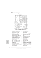 2
2 -
 3
3 -
 4
4 -
 5
5 -
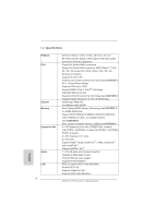 6
6 -
 7
7 -
8
-
9
-
10
-
11
-
12
-
13
-
14
-
15
-
16
-
17
-
18
-
19
-
20
-
21
-
22
-
23
-
24
-
25
-
26
-
27
-
28
-
29
-
30
-
31
-
32
-
33
-
34
-
35
-
36
-
37
-
38
-
39
-
40
-
41
-
42
-
43
-
44
-
45
-
46
-
47
-
48
-
49
-
50
-
51
-
52
-
53
-
54
-
55
-
56
-
57
-
58
-
59
-
60
-
61
-
62
-
63
-
64
-
65
-
66
-
67
-
68
-
69
-
70
-
71
-
72
-
73
-
74
-
75
-
76
-
77
-
78
-
79
-
80
-
81
-
82
-
83
-
84
-
85
-
86
-
87
-
88
-
89
-
90
-
91
-
92
-
93
-
94
-
95
-
96
-
97
-
98
-
99
-
100
-
101
-
102
-
103
-
104
-
105
-
106
-
107
-
108
-
109
-
110
-
111
-
112
-
113
-
114
-
115
-
116
-
117
-
118
-
119
-
120
-
121
-
122
-
123
-
124
-
125
-
126
-
127
-
128
-
129
-
130
-
131
-
132
-
133
-
134
-
135
-
136
-
137
-
138
-
139
-
140
-
141
-
142
-
143
-
144
-
145
-
146
-
147
-
148
-
149
-
150
-
151
-
152
-
153
-
154
-
155
-
156
-
157
-
158
-
159
-
160
-
161
-
162
-
163
-
164
-
165
-
166
-
167
-
168
-
169
-
170
-
171
-
172
-
173
-
174
-
175
-
176
-
177
-
178
-
179
-
180
-
181
-
182
-
183
-
184
-
185
-
186
-
187
-
188
-
189
-
190
-
191
-
192
-
193
-
194
-
195
-
196
-
197
-
198
-
199
-
200
-
201
-
202
-
203
-
204
-
205
-
206
-
207
-
208
-
209
-
210
-
211
-
212
-
213
-
214
-
215
-
216
-
217
-
218
-
219
-
220
-
221
-
222
-
223
-
224
-
225
-
226
-
227
-
228
-
229
-
230
-
231
-
232
-
233
-
234
-
235
-
236
-
237
-
238
-
239
-
240
-
241
-
242
-
243
-
244
-
245
-
246
-
247
-
248
-
249
-
250
-
251
-
252
-
253
-
254
-
255
-
256
-
257
-
258
-
259
-
260
-
261
-
262
-
263
-
264
-
265
-
266
-
267
-
268
-
269
-
270
-
271
-
272
-
273
-
274
-
275
-
276
-
277
-
278
-
279
-
280
-
281
-
282
-
283
 |
 |

1
ASRock
970 Extreme4
Motherboard
English
Copyright Notice:
No part of this installation guide may be reproduced, transcribed, transmitted, or trans-
lated in any language, in any form or by any means, except duplication of documentation
by the purchaser for backup purpose, without written consent of ASRock Inc.
Products and corporate names appearing in this guide may or may not be registered
trademarks or copyrights of their respective companies, and are used only for identi
fi
ca-
tion or explanation and to the owners’ bene
fi
t, without intent to infringe.
Disclaimer:
Speci
fi
cations and information contained in this guide are furnished for informational use
only and subject to change without notice, and should not be constructed as a commit-
ment by ASRock. ASRock assumes no responsibility for any errors or omissions that may
appear in this guide.
With respect to the contents of this guide, ASRock does not provide warranty of any kind,
either expressed or implied, including but not limited to the implied warranties or condi-
tions of merchantability or
fi
tness for a particular purpose. In no event shall ASRock, its
directors, of
fi
cers, employees, or agents be liable for any indirect, special, incidental, or
consequential damages (including damages for loss of pro
fi
ts, loss of business, loss of
data, interruption of business and the like), even if ASRock has been advised of the pos-
sibility of such damages arising from any defect or error in the guide or product.
This device complies with Part 15 of the FCC Rules. Operation is subject to the following
two conditions:
(1) this device may not cause harmful interference, and
(2) this device must accept any interference received, including interference that
may cause undesired operation.
CALIFORNIA, USA ONLY
The Lithium battery adopted on this motherboard contains Perchlorate, a toxic substance
controlled in Perchlorate Best Management Practices (BMP) regulations passed by the
California Legislature. When you discard the Lithium battery in California, USA, please
follow the related regulations in advance.
“Perchlorate Material-special handling may apply, see
www.dtsc.ca.gov/hazardouswaste/perchlorate”
ASRock Website: http://www.asrock.com
Published May 2011
Copyright
©
2011 ASRock INC. All rights reserved.