ASRock ALiveNF7G-FullHD R1.0 User Manual
ASRock ALiveNF7G-FullHD R1.0 Manual
 |
View all ASRock ALiveNF7G-FullHD R1.0 manuals
Add to My Manuals
Save this manual to your list of manuals |
ASRock ALiveNF7G-FullHD R1.0 manual content summary:
- ASRock ALiveNF7G-FullHD R1.0 | User Manual - Page 1
ALiveNF7G-FullHD User Manual Version 1.1/3.1 Published February 2008 Copyright©2008 ASRock INC. All rights reserved. 1 - ASRock ALiveNF7G-FullHD R1.0 | User Manual - Page 2
any form or by any means, except duplication of documentation by the purchaser for backup purpose, without written consent of ASRock Inc. Products and corporate names appearing in this manual may or may not be registered trademarks or copyrights of their respective companies, and are used only for - ASRock ALiveNF7G-FullHD R1.0 | User Manual - Page 3
HD-DVD Playback Support 10 1.5 1080p Blu-ray (BD) / HD-DVD Films Which Pass Our Lab Test . 11 1.6 Motherboard Layout (ALiveNF7G-FullHD R1.0 12 1.7 Motherboard Layout (ALiveNF7G-FullHD R3.0 13 1.8 ASRock and Operation Guide ....... 33 2.14 Driver Installation Guide 35 2.15 Installing Windows® 2000 - ASRock ALiveNF7G-FullHD R1.0 | User Manual - Page 4
3.5 Boot Screen 54 3.5.1 Boot Settings Configuration 54 3.6 Security Screen 55 3.7 Exit Screen 56 4 . Software Support 57 4.1 Install Operating System 57 4.2 Support CD Information 57 4.2.1 Running Support CD 57 4.2.2 Drivers Menu 57 4.2.3 Utilities Menu 57 4.2.4 Contact Information 57 4 - ASRock ALiveNF7G-FullHD R1.0 | User Manual - Page 5
the model you are using. www.asrock.com/support/index.asp 1.1 Package Contents 1 x ASRock ALiveNF7G-FullHD Motherboard (Micro ATX Form Factor: 9.6-in x 8.6-in, 24.4 cm x 21.8 cm) 1 x ASRock ALiveNF7G-FullHD Quick Installation Guide 2 x ASRock ALiveNF7G-FullHD Support CD 1 x Ultra ATA 66/100/133 - ASRock ALiveNF7G-FullHD R1.0 | User Manual - Page 6
CH Windows® VistaTM Premium Level HD Audio (ALC662 Audio Codec) - Chipset embedded HDMI Audio - Realtek PHY RTL8201CL (ALiveNF7G-FullHD R1.0) - Speed: 10/100 Ethernet (ALiveNF7G-FullHD R1.0) - Gigabit LAN 10/100/1000 Mb/s (ALiveNF7G-FullHD R3.0) - Giga PHY RTL8211B (ALiveNF7G-FullHD R3.0) - Supports - ASRock ALiveNF7G-FullHD R1.0 | User Manual - Page 7
Events - Supports jumperfree - SMBIOS 2.3.1 Support - Drivers, Utilities, AntiVirus Software (Trial Version) - CPU Temperature Sensing - Chassis Temperature Sensing - CPU Fan Tachometer - Chassis Fan Tachometer - CPU Quiet Fan - Voltage Monitoring: +12V, +5V, +3.3V, Vcore - Microsoft® Windows® 2000 - ASRock ALiveNF7G-FullHD R1.0 | User Manual - Page 8
the installation guide of memory modules on page 17 for proper installation. 3. Whether 1066MHz memory speed is supported depends on the AM2+ CPU you heatsink when you install the PC system. 7. This motherboard supports ASRock AM2 Boost overclocking technology. If you enable this function in the - ASRock ALiveNF7G-FullHD R1.0 | User Manual - Page 9
read the "SATAII Hard Disk Setup Guide" on page 31 to adjust Windows® VistaTM 64-bit / VistaTM / XP 64-bit / XP SP1 or SP2 / 2000 SP4. 13. WiFi/E header supports WiFi+AP function with ASRock Driver DVI with HDCP * If you use onboard VGA with total system memory size 512MB and plan to submit Windows - ASRock ALiveNF7G-FullHD R1.0 | User Manual - Page 10
/ HD-DVD playback support on this motherboard requires the proper hardware configuration. Please refer to below table for the minimum hardware requirement. CPU VGA Memory Suggested OS AMD Phenom X4 9100 Onboard VGA with DVI-D port Dual Channel DDR2 800, 1GB x 2 Windows® VistaTM or Windows® VistaTM - ASRock ALiveNF7G-FullHD R1.0 | User Manual - Page 11
GLORY ROAD MPEG-4-AVC THE LEAGUE OF MPEG-4-AVC EXTRAORDINARY GENTLEMEN HD- KING KONG VC-1 DVD MISSION IMPOSSIBLE III VC-1 THE CHRONICLES port Memory Dual Channel DDR2 800, 1GB x 2 OS Windows® VistaTM or Windows® VistaTM 64 Playback Software CyberLink PowerDVD Ultra DVD Player Pioneer - ASRock ALiveNF7G-FullHD R1.0 | User Manual - Page 12
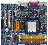
1.6 Motherboard Layout (ALiveNF7G-FullHD R1.0) 12 3 45 21.8cm (8.6-in) 1 PS2_USB_PW1 ATX12V1 67 Panel Header (PANEL1) 3 ATX 12V Power Connector (ATX12V1) 19 SPI Flash Memory (4Mb) 4 AM2 940-Pin CPU Socket 20 DeskExpress Hot Plug Detection Header 5 CPU Heatsink Retention Module (IR1) 6 - ASRock ALiveNF7G-FullHD R1.0 | User Manual - Page 13
1.7 Motherboard Layout (ALiveNF7G-FullHD R3.0) 12 3 45 21.8cm (8.6-in) 1 PS2_USB_PW1 ATX12V1 B: USB1 Top: RJ-45 AM2+ Quad Core CPU ATXPWR1 Top: LINE IN Center: FRONT Bottom: MIC IN USB 2.0 T: USB2 B: USB3 LAN PHY CD1 1 HD_AUDIO1 AUDIO CODEC ALiveNF7G-FullHD PCIE1 NVIDIA GeForce 7050 / - ASRock ALiveNF7G-FullHD R1.0 | User Manual - Page 14
1.8 ASRock 6CH_DVI I/O 1 2 3 4 5 6 11 10 1 PS/2 Mouse Port (Green) 2 Parallel Port 3 RJ-45 Port 4 Line In (Light use front panel audio. Then reboot your system. For Windows® VistaTM: After restarting your computer, please double-click "Realtek HD Audio Manager" on the system tray. Set "Speaker - ASRock ALiveNF7G-FullHD R1.0 | User Manual - Page 15
2. Installation This is a Micro ATX form factor (9.6-in x 8.6-in, 24.4 cm x 21.8 cm) motherboard. Before you install the motherboard, study the configuration of your chassis to ensure that the motherboard fits into it. Pre-installation Precautions Take note of the following precautions before you - ASRock ALiveNF7G-FullHD R1.0 | User Manual - Page 16
other. Then connect the CPU fan to the CPU FAN connector (CPU_FAN1, see Page 12/13, No. 2). For proper installation, please kindly refer to the instruction manuals of the CPU fan and the heatsink. 16 - ASRock ALiveNF7G-FullHD R1.0 | User Manual - Page 17
2.3 Installation of Memory Modules (DIMM) This motherboard provides four 240-pin DDR2 (Double Data Rate 2) DIMM slots, and supports Dual Channel Memory Technology. For dual channel configuration, you always need to install identical (the same brand, speed, size and chip-type) DDR2 DIMM pair - ASRock ALiveNF7G-FullHD R1.0 | User Manual - Page 18
Installing a DIMM Please make sure to disconnect power supply before adding or removing DIMMs or the system components. Step 1. Step 2. Unlock a DIMM slot by pressing the retaining clips outward. Align a DIMM on the slot such that the notch on the DIMM matches the break on the slot. notch break - ASRock ALiveNF7G-FullHD R1.0 | User Manual - Page 19
2.4 Expansion Slots (PCI and PCI Express Slots) There are 2 PCI slots and 2 PCI Express slots on this motherboard. PCI slots: PCI slots are used to install expansion cards that have the 32-bit PCI interface. PCIE slots: PCIE1 (PCIE x1 slot) is used for PCI Express cards with x1 lane width cards, - ASRock ALiveNF7G-FullHD R1.0 | User Manual - Page 20
yet, please install onboard VGA driver from our support CD to your system and restart your computer. Then you can start to use dual monitor function provided by VGA/DVI-D and VGA/D-Sub ports with this motherboard. When you playback HDCP-protected video from Blu-ray (BD) or HD-DVD disc, the content - ASRock ALiveNF7G-FullHD R1.0 | User Manual - Page 21
display upgrade. With the internal dual VGA output support (DVI-D and D-Sub) and the external add you have installed the onboard VGA driver and the add-on PCI Express VGA card driver already, there is no need to install them again. 5. Set up a multi-monitor display. For Windows® 2000 / XP / XP - ASRock ALiveNF7G-FullHD R1.0 | User Manual - Page 22
function with this motherboard, you need to adopt the monitor that supports HDCP function as well. Therefore, you can enjoy the superior display quality with high-definition HDCP encryption contents. Please refer to below instruction for more details about HDCP function. What is HDCP? HDCP stands - ASRock ALiveNF7G-FullHD R1.0 | User Manual - Page 23
sometimes. For Windows® XP / XP 64-bit OS Step 1: Set up BIOS. A. Enter BIOS SETUP UTILITY Advanced screen Chipset Configuration. B. Set the option "OnBoard HDMI HD Audio" to [Auto]. Step 2: Install HDMI audio driver to your system. Install "Onboard HDMI HD Audio Driver" from ASRock Support CD to - ASRock ALiveNF7G-FullHD R1.0 | User Manual - Page 24
2.7 Jumpers Setup The illustration shows how jumpers are setup. When the jumper cap is placed on pins, the jumper is "Short". If no jumper cap is placed on pins, the jumper is "Open". The illustration shows a 3-pin jumper whose pin1 and pin2 are "Short" when jumper cap is placed on these 2 pins. - ASRock ALiveNF7G-FullHD R1.0 | User Manual - Page 25
IDE devices 80-conductor ATA 66/100/133 cable Note: Please refer to the instruction of your IDE device vendor for the details. Serial ATAII Connectors (SATAII_1 (PORT SATAII_4 (PORT 3) These four Serial ATAII (SATAII) connectors support SATAII or SATA hard disk for internal storage devices. The - ASRock ALiveNF7G-FullHD R1.0 | User Manual - Page 26
Front Panel Audio Header (9-pin HD_AUDIO1) (see p.12/13, No. 28) GND PRESENCE# MIC_RET OUT_RET 1 OUT2_L J_SENSE OUT2_R MIC2_R MIC2_L 26 This header supports WiFi+AP function with ASRock WiFi-802.11g or WiFi-802.11n module, an easy-to-use wireless local area network (WLAN) adapter. It allows you to - ASRock ALiveNF7G-FullHD R1.0 | User Manual - Page 27
wire on the chassis must support HDA to function correctly. Please follow the instruction in our manual and chassis manual to install your system. 2. [Enabled]. F. Enter Windows system. Click the icon on the lower right hand taskbar to enter Realtek HD Audio Manager. For Windows® 2000 / XP - ASRock ALiveNF7G-FullHD R1.0 | User Manual - Page 28
Though this motherboard provides 4-Pin CPU fan (Quiet Fan) support, the 3-Pin CPU fan still can work successfully even without the fan speed control function. If cause power up failure. RRXD1 DDTR#1 DDSR#1 CCTS#1 1 RRI#1 RRTS#1 GND TTXD1 DDCD#1 This COM1 header supports a serial port module. 28 - ASRock ALiveNF7G-FullHD R1.0 | User Manual - Page 29
HDMI_SPDIF Header (3-pin HDMI_SPDIF1) (see p.12/13 No. 25) 1 GND SPDIFOUT +5V HDMI_SPDIF header, providing SPDIF audio output to HDMI VGA card, allows the system to connect HDMI Digital TV/ projector/LCD devices. Please connect the HDMI_SPDIF connector of HDMI VGA card to this header. HDMI_SPDIF - ASRock ALiveNF7G-FullHD R1.0 | User Manual - Page 30
Guide installation of HDMI VGA card, please refer to the installation guide on page 19. Step 2. Connect the black end VGA card, please refer to the user manual of HDMI VGA card vendor. Incorrect connection card. Please refer to the VGA card user manual for connector usage in advance. Step 4. Step - ASRock ALiveNF7G-FullHD R1.0 | User Manual - Page 31
guide. Some default setting of SATAII hard disks may not be at SATAII mode, which operate with the best performance. In order to enable SATAII function, please follow the below instruction 's website for details: http://www.hitachigst.com/hdd/support/download.htm The above examples are just for your - ASRock ALiveNF7G-FullHD R1.0 | User Manual - Page 32
hard disks on this motherboard for internal storage devices. This section will guide you to install the SATA / SATAII hard disks. STEP 1: Install Plug and Hot Swap Functions for SATA / SATAII HDDs This motherboard supports Hot Plug and Hot Swap functions for SATA / SATAII Devices in RAID - ASRock ALiveNF7G-FullHD R1.0 | User Manual - Page 33
is installed into system properly. The latest SATA / SATAII driver is available on our support website: www.asrock.com 4. Make sure to use the SATA power cable & data cable, which are from our motherboard package. 5. Please follow below instructions step by step to reduce the risk of HDD crash or - ASRock ALiveNF7G-FullHD R1.0 | User Manual - Page 34
the SATA / SATAII HDD. How to Hot Unplug a SATA / SATAII HDD: Points of attention, before you process the Hot Unplug: Please do follow below instruction sequence to process the Hot Unplug, improper procedure will cause the SATA / SATAII HDD damage and data loss. Step 1 Unplug SATA data cable from - ASRock ALiveNF7G-FullHD R1.0 | User Manual - Page 35
Mode" option to [AHCI]. STEP 2: Make a SATA / SATAII driver diskette. A. Insert the ASRock Support CD into your optical drive to boot your system. (There are two ASRock Support CD in the motherboard gift box pack, please choose the one for Windows® 2000 / XP / XP 64-bit.) B. During POST at - ASRock ALiveNF7G-FullHD R1.0 | User Manual - Page 36
system will start to format the floppy diskette and copy SATA / SATAII drivers into the floppy diskette. STEP 3: Install Windows® 2000 / XP / XP 64-bit OS on your system. After making a SATA / SATAII driver diskette, you can start to install Windows® 2000 / XP / XP 64-bit on your system. At the - ASRock ALiveNF7G-FullHD R1.0 | User Manual - Page 37
to boot your system, and follow the instruction to install Windows® VistaTM / Windows® VistaTM 64-bit OS on your system. When you see "Where do you want to install Windows?" page, please insert the ASRock Support CD into your optical drive, and click the "Load Driver" button on the left on the - ASRock ALiveNF7G-FullHD R1.0 | User Manual - Page 38
the Support CD: .. \ RAID Installation Guide NOTE. Currently, the RAID driver for Windows® 2000 / Windows® XP / Windows® XP 64-bit OS is not ready yet. As long as we get the Windows® 2000 / Windows® XP / Windows® XP 64-bit RAID driver, we will update it to our website in the future. ASRock website - ASRock ALiveNF7G-FullHD R1.0 | User Manual - Page 39
to boot your system, and follow the instruction to install Windows® VistaTM / Windows® VistaTM 64-bit OS on your system. When you see "Where do you want to install Windows?" page, please insert the ASRock Support CD into your optical drive, and click the "Load Driver" button on the left on the - ASRock ALiveNF7G-FullHD R1.0 | User Manual - Page 40
3. BIOS SETUP UTILITY 3.1 Introduction This section explains how to use the BIOS SETUP UTILITY to configure your system. The Flash Memory on the motherboard stores the BIOS SETUP UTILITY. You may run the BIOS SETUP UTILITY when you start up the computer. Please press during the Power-On-Self- - ASRock ALiveNF7G-FullHD R1.0 | User Manual - Page 41
. BIOS SETUP UTILITY Main Advanced H/W Monitor Boot Security Exit System Overview System Time System Date [17:00:09] [Wed 01/30/2008] BIOS Version : ALiveNF7G-FullHD BIOS P1.0 Processor Type : AMD Athlon(tm) 64 Processor 3500+ (64bit) Processor Speed : 2200 MHz Microcode Update : 40FF2/0 L1 - ASRock ALiveNF7G-FullHD R1.0 | User Manual - Page 42
If AUTO, multiplier and voltage will be left at the rated frequency/voltage. If Manual, multiplier and voltage will be set based on User Selection in Setup. +F1 , American Megatrends, Inc. AM2 Boost If you set this option to [Enabled], you will enable ASRock AM2 Boost function, which will improve - ASRock ALiveNF7G-FullHD R1.0 | User Manual - Page 43
] and [Disabled]. If you install Windows® VistaTM and want to enable this function support the Halt State (C1). The C1 state is supported through the native processor instructions HLT and MWAIT and requires no hardware support default. If it is set to [Manual], you may adjust the value of Processor - ASRock ALiveNF7G-FullHD R1.0 | User Manual - Page 44
BIOS SETUP UTILITY Advanced CPU Configuration AM2 Boost Overclock Mode CPU Frequency (MHz) PCIE Frequency ( this item. Processor Voltage This item will show when "Multiplier/Voltage Change" is set to [Manual]; otherwise, it will be hidden. The range of the value depends on the CPU you adopt on - ASRock ALiveNF7G-FullHD R1.0 | User Manual - Page 45
TRAS Use this to adjust TRAS values. Configuration options: [Auto], [5CLK] to [18CLK]. The default value is [Auto]. TRRD Use this to adjust TRRD values. Configuration options: [Auto], [2CLK], [3CLK], [4CLK] and [5CLK]. The default value is [Auto]. TRC Use this to adjust TRC values. Configuration - ASRock ALiveNF7G-FullHD R1.0 | User Manual - Page 46
will be disabled when PCI Sound Card is plugged. Front Panel Select [Auto], [Enabled] or [Disabled] for the onboard HD Audio Front Panel. Share Memory This allows you to set share memory feature. The default value is [Auto]. Configuration options: [Auto], [32MB], [64MB], [128MB] and [ - ASRock ALiveNF7G-FullHD R1.0 | User Manual - Page 47
Suspend-toRAM feature. Select [Auto] will enable this feature if the OS supports it. If you set this item to [Disabled], the function "Repost Video the feature Check Ready Bit. Away Mode Support Use this item to enable or disable Away Mode support under Windows® XP Media Center OS. The default value - ASRock ALiveNF7G-FullHD R1.0 | User Manual - Page 48
if you plan to use this motherboard to submit Windows® VistaTM certification. 3.3.4 IDE Configuration BIOS SETUP UTILITY can not be accessed until you finish configuring RAID functions in NVIDIA BIOS / Windows RAID Utility. IDE Device Configuration You may set the IDE configuration for the device - ASRock ALiveNF7G-FullHD R1.0 | User Manual - Page 49
:Hard Disk :MAXTOR 6L080J4 :80.0 GB :Supported :16Sectors :4 :MultiWord DMA-2 :Ultra DMA-6 :Supported Type LBA/Large Mode Block (Multi-Sector Transfer select the LBA/Large mode for a hard disk > 512 MB under DOS and Windows; for Netware and UNIX user, select [Disabled] to disable the LBA/Large mode - ASRock ALiveNF7G-FullHD R1.0 | User Manual - Page 50
S.M.A.R.T. Use this item to enable or disable the S.M.A.R.T. (Self-Monitoring, Analysis, and Reporting Technology) feature. Configuration options: [Disabled], [Auto], [Enabled]. 32Bit Data Transfer Use this item to enable 32-bit access to maximize the IDE hard disk data transfer rate. 3.3.5 PCIPnP - ASRock ALiveNF7G-FullHD R1.0 | User Manual - Page 51
to set the address for the onboard infrared port or disable it. Configuration options: [Disabled], [2F8 / IRQ3], and [2E8 / IRQ3]. If you plan to use ASRock DeskExpress on this motherboard, please keep this item on [Disabled] option. 51 - ASRock ALiveNF7G-FullHD R1.0 | User Manual - Page 52
parallel port. Configuration options: [IRQ5] and [IRQ7]. 3.3.8 USB Configuration BIOS SETUP UTILITY Advanced USB Configuration USB Controller USB 2.0 Support Legacy USB Support [Enabled] [Enabled] [Disabled] To enable or disable the onboard USB controllers. +F1 F9 F10 ESC Select Screen Select - ASRock ALiveNF7G-FullHD R1.0 | User Manual - Page 53
3.4 Hardware Health Event Monitoring Screen In this section, it allows you to monitor the status of the hardware on your system, including the parameters of the CPU temperature, motherboard temperature, CPU fan speed, chassis fan speed, and the critical voltage. BIOS SETUP UTILITY Main Advanced - ASRock ALiveNF7G-FullHD R1.0 | User Manual - Page 54
3.5 Boot Screen In this section, it will display the available devices on your system for you to configure the boot settings and the boot priority. Main BIOS SETUP UTILITY Advanced H/W Monitor Boot Security Exit Boot Settings Boot Settings Configuration 1st Boot Device 2nd Boot Device 3rd - ASRock ALiveNF7G-FullHD R1.0 | User Manual - Page 55
3.6 Security Screen In this section, you may set or change the supervisor/user password for the system. For the user password, you may also clear it. BIOS SETUP UTILITY Main Advanced H/W Monitor Boot Security Exit Security Settings Supervisor Password : Not Installed User Password : Not - ASRock ALiveNF7G-FullHD R1.0 | User Manual - Page 56
3.7 Exit Screen Main BIOS SETUP UTILITY Advanced H/W Monitro Boot Security Exit Exit Options Save Changes and Exit Discard Changes and Exit Discard Changes Load Optimal Defaults Exit system setup after saving the changes. F10 key can be used for this operation. Select Screen Select Item - ASRock ALiveNF7G-FullHD R1.0 | User Manual - Page 57
install the necessary drivers to activate the devices. 4.2.3 Utilities Menu The Utilities Menu shows the applications software that the motherboard supports. Click on a specific item then follow the installation wizard to install it. 4.2.4 Contact Information If you need to contact ASRock or want to
-
 1
1 -
 2
2 -
 3
3 -
 4
4 -
 5
5 -
 6
6 -
 7
7 -
8
-
9
-
10
-
11
-
12
-
13
-
14
-
15
-
16
-
17
-
18
-
19
-
20
-
21
-
22
-
23
-
24
-
25
-
26
-
27
-
28
-
29
-
30
-
31
-
32
-
33
-
34
-
35
-
36
-
37
-
38
-
39
-
40
-
41
-
42
-
43
-
44
-
45
-
46
-
47
-
48
-
49
-
50
-
51
-
52
-
53
-
54
-
55
-
56
-
57
 |
 |
1
ALiveNF7G-FullHD
User Manual
Version 1.
1
/3.
1
Published
Febr
uary 2008
Copyright©2008 ASRock INC. All rights reserved.