ASRock ALiveNF7G-GLAN User Manual
ASRock ALiveNF7G-GLAN Manual
 |
View all ASRock ALiveNF7G-GLAN manuals
Add to My Manuals
Save this manual to your list of manuals |
ASRock ALiveNF7G-GLAN manual content summary:
- ASRock ALiveNF7G-GLAN | User Manual - Page 1
ALiveNF7G-GLAN User Manual Version 1.0 Published February 2009 Copyright©2009 ASRock INC. All rights reserved. 1 - ASRock ALiveNF7G-GLAN | User Manual - Page 2
purchaser for backup purpose, without written consent of ASRock Inc. Products and corporate names appearing in this manual may or may not be registered trademarks or copyrights USA ONLY The Lithium battery adopted on this motherboard contains Perchlorate, a toxic substance controlled in Perchlorate - ASRock ALiveNF7G-GLAN | User Manual - Page 3
Blu-ray (BD) / HD-DVD Playback Support 10 1.4 1080p Blu-ray (BD) / HD-DVD Films Which Pass Our Lab Test . 11 1.5 Motherboard Layout 12 1.6 I/O Panel 13 2 . Installation 14 Pre-installation Precautions 14 2.1 CPU Installation 15 2.2 Installation of CPU Fan and Heatsink 15 2.3 Installation of - ASRock ALiveNF7G-GLAN | User Manual - Page 4
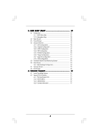
3.1.1 BIOS Menu Bar 37 3.1.2 Navigation Keys 38 3.2 Main Screen 38 3.3 Smart Screen 39 3.4 Advanced Screen 40 3.4.1 CPU Configuration 56 4 . Software Support 57 4.1 Install Operating System 57 4.2 Support CD Information 57 4.2.1 Running Support CD 57 4.2.2 Drivers Menu 57 4.2.3 Utilities - ASRock ALiveNF7G-GLAN | User Manual - Page 5
about the model you are using. www.asrock.com/support/index.asp 1.1 Package Contents 1 x ASRock ALiveNF7G-GLAN Motherboard (Micro ATX Form Factor: 9.6-in x 8.2-in, 24.4 cm x 20.8 cm) 1 x ASRock ALiveNF7G-GLAN Quick Installation Guide 2 x ASRock ALiveNF7G-GLAN Support CD 1 x Ultra ATA 66/100/133 IDE - ASRock ALiveNF7G-GLAN | User Manual - Page 6
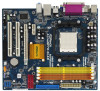
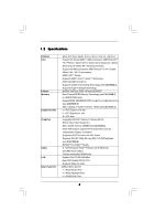
1.2 Specifications Platform CPU Chipset Memory Expansion Slot Graphics Audio LAN Rear Panel I/O - Micro ATX Form Factor: 9.6-in x 8.2-in, 24.4 cm x 20.8 cm - Support for Socket AM2+ / AM2 processors: AMD PhenomTM FX / Phenom / Athlon 64 FX / Athlon 64 X2 Dual-Core / Athlon X2 Dual-Core / Athlon 64 - ASRock ALiveNF7G-GLAN | User Manual - Page 7
" - ACPI 1.1 Compliance Wake Up Events - Supports jumperfree - SMBIOS 2.3.1 Support - Supports Smart BIOS - Drivers, Utilities, AntiVirus Software (Trial Version) - ASRock OC Tuner (see CAUTION 10) - Intelligent Energy Saver (see CAUTION 11) - Instant Boot - Hybrid Booster: - CPU Frequency Stepless - ASRock ALiveNF7G-GLAN | User Manual - Page 8
supported depends on the AM2+ CPU you adopt. If you want to adopt DDR2 1066 memory module on this motherboard, please refer to the memory support list on our website for the compatible memory modules. ASRock website http://www.asrock read the "SATAII Hard Disk Setup Guide" on page 28 to adjust your - ASRock ALiveNF7G-GLAN | User Manual - Page 9
under Windows® environment. Please visit our website for the operation procedures of ASRock OC Tuner. ASRock website: http://www.asrock. CPU and the heatsink when you install the PC system. 14. This motherboard supports ASRock AM2 Boost overclocking technology. If you enable this function in the BIOS - ASRock ALiveNF7G-GLAN | User Manual - Page 10
-DVD playback support on this motherboard requires the proper hardware configuration. Please refer to below table for the minimum hardware requirement. CPU VGA Memory Suggested OS AMD Phenom X4 9100 Onboard VGA with DVI-D port Dual Channel DDR2 800, 1GB x 2 Windows® VistaTM or Windows® VistaTM 64 - ASRock ALiveNF7G-GLAN | User Manual - Page 11
(BD) / HD-DVD Films in Our Lab Test DVD Film Name Format Type Blu-ray SWORDFISH VC-1 DVD THE TRANSPORTER tested under below configuration. Items Configurations CPU AMD Phenom X4 9100 VGA Onboard VGA with DVI-D port Memory Dual Channel DDR2 800, 1GB x 2 OS Windows® VistaTM or Windows - ASRock ALiveNF7G-GLAN | User Manual - Page 12
-pin module) AT X P W R 1 24.4cm (9.6-in) PARALLEL PORT SOCKET AM2 VGA1 30 29 28 27 Top: Line In Center: Line Out Bottom: Mic In USB 2.0 T: USB2 B: USB3 USB 2.0 T: USB0 B: USB1 Top: RJ-45 LAN PHY Phenom II DDR2 1066 ALiveNF7G-GLAN Dual Channel PCIE1 NVIDIA GeForce 7050 / nForce 630A MCP - ASRock ALiveNF7G-GLAN | User Manual - Page 13
1.6 ASRock 6CH_DVI I/O 1 2 3 4 5 6 11 10 9 87 1 PS/2 Mouse next to the LAN port. Please refer to the table below for the LAN port LED indications. LAN Port LED Indications steps for the software setting of Multi-Streaming. For Windows® XP: After restarting your computer, you will find - ASRock ALiveNF7G-GLAN | User Manual - Page 14
2. Installation This is a Micro ATX form factor (9.6-in x 8.2-in, 24.4 cm x 20.8 cm) motherboard. Before you install the motherboard, study the configuration of your chassis to ensure that the motherboard fits into it. Pre-installation Precautions Take note of the following precautions before you - ASRock ALiveNF7G-GLAN | User Manual - Page 15
Socker Corner Small Triangle STEP 2 / STEP 3: Match The CPU Golden Triangle To The Socket Corner Small Triangle STEP 4: Push Down And Lock The Socket Lever 2.2 Installation of CPU Fan and Heatsink After you install the CPU into this motherboard, it is necessary to install a larger heatsink and - ASRock ALiveNF7G-GLAN | User Manual - Page 16
2.3 Installation of Memory Modules (DIMM) This motherboard provides four 240-pin DDR2 (Double Data Rate 2) DIMM slots, and supports Dual Channel Memory Technology. For dual channel configuration, you always need to install identical (the same brand, speed, size and chip-type) DDR2 DIMM pair - ASRock ALiveNF7G-GLAN | User Manual - Page 17
matches the break on the slot. notch break notch break The DIMM only fits in one correct orientation. It will cause permanent damage to the motherboard and the DIMM if you force the DIMM into the slot at incorrect orientation. Step 3. Firmly insert the DIMM into the slot until the retaining - ASRock ALiveNF7G-GLAN | User Manual - Page 18
Slots) There are 2 PCI slots and 2 PCI Express slots on this motherboard. PCI slots: PCI slots are used to install expansion cards that have x1 slot) is used for PCI Express cards with x1 lane width cards, such as Gigabit LAN card, SATA2 card, etc. PCIE2 (PCIE x16 slot) is used for PCI Express cards - ASRock ALiveNF7G-GLAN | User Manual - Page 19
benefits of dual monitor function provided by VGA/DVI-D and VGA/D-Sub ports with this motherboard after your system boots. If you haven't installed onboard VGA driver yet, please install onboard VGA driver from our support CD to your system and restart your computer. Then you can start to use dual - ASRock ALiveNF7G-GLAN | User Manual - Page 20
BIOS setup, the default value of "Share Memory", [Auto], will disable VGA/D-Sub function when the add-on VGA card is inserted to this motherboard. 4. Install the onboard VGA driver and the add-on PCI Express VGA card driver one, two, three and four. For Windows® VistaTM / VistaTM 64-bit OS: Right - ASRock ALiveNF7G-GLAN | User Manual - Page 21
DVI-D port on this motherboard. To use HDCP function with this motherboard, you need to adopt the monitor that supports HDCP function as well. Therefore, you can enjoy the superior display quality with high-definition HDCP encryption contents. Please refer to below instruction for more details about - ASRock ALiveNF7G-GLAN | User Manual - Page 22
sometimes. For Windows® XP / XP 64-bit OS Step 1: Set up BIOS. A. Enter BIOS SETUP UTILITY Advanced screen Chipset Configuration. B. Set the option "OnBoard HDMI HD Audio" to [Auto]. Step 2: Install HDMI audio driver to your system. Install "Onboard HDMI HD Audio Driver" from ASRock Support CD to - ASRock ALiveNF7G-GLAN | User Manual - Page 23
see p.12, No. 1) +5V +5VSB +5VSB (standby) for PS/2 or USB wake up events. Note: To select +5VSB, it requires 2 Amp and higher standby current not clear the CMOS right after you update the BIOS. If you need to clear the CMOS when you just finish updating the BIOS, you must boot up the system - ASRock ALiveNF7G-GLAN | User Manual - Page 24
end to the motherboard connect the black end to the IDE devices 80-conductor ATA 66/100/133 cable Note: Please refer to the instruction of your IDE device Data Cable (Optional) These four Serial ATAII (SATAII) connectors support SATAII or SATA hard disk for internal storage devices. The current - ASRock ALiveNF7G-GLAN | User Manual - Page 25
panel, there are three USB 2.0 headers on this motherboard. Each USB 2.0 header can support two USB 2.0 ports. Infrared Module Header (5-pin supports Jack Sensing, but the panel wire on the chassis must support HDA to function correctly. Please follow the instruction in our manual and chassis manual - ASRock ALiveNF7G-GLAN | User Manual - Page 26
BIOS Setup Utility. Enter Advanced Settings, and then select Chipset Configuration. Set the Front Panel Control option from [Auto] to [Enabled]. F. Enter Windows pin. CPU Fan Connector (4-pin CPU_FAN1) (see p.12 No. 5) 4 3 2 1 GND +12V CPU_FAN_SPEED FAN_SPEED_CONTROL Please connect the CPU fan - ASRock ALiveNF7G-GLAN | User Manual - Page 27
4-Pin CPU fan (Quiet Fan) support, the 3-Pin CPU fan still can work successfully even without the fan speed control function. If you plan to connect the 3-Pin CPU fan to the CPU fan connector on this motherboard, please connect it to Pin 1-3. Pin 1-3 Connected 3-Pin Fan Installation ATX Power - ASRock ALiveNF7G-GLAN | User Manual - Page 28
guide. Some default setting of SATAII hard disks may not be at SATAII mode, which operate with the best performance. In order to enable SATAII function, please follow the below instruction website for details: http://www.hitachigst.com/hdd/support/download.htm The above examples are just for your - ASRock ALiveNF7G-GLAN | User Manual - Page 29
NVIDIA® GeForce 7050 / nForce 630A MCP chipset that supports Serial ATA (SATA) / Serial ATAII (SATAII) hard disks and RAID functions. You may install SATA / SATAII hard disks on this motherboard for internal storage devices. This section will guide you to install the SATA / SATAII hard disks. STEP - ASRock ALiveNF7G-GLAN | User Manual - Page 30
is installed into system properly. The latest SATA / SATAII driver is available on our support website: www.asrock.com 4. Make sure to use the SATA power cable & data cable, which are from our motherboard package. 5. Please follow below instructions step by step to reduce the risk of HDD crash or - ASRock ALiveNF7G-GLAN | User Manual - Page 31
cable to (White) to the power supply 1x4-pin cable. the motherboard's SATAII connector. SATA power cable 1x4-pin power connector (White) Step attention, before you process the Hot Unplug: Please do follow below instruction sequence to process the Hot Unplug, improper procedure will cause the SATA - ASRock ALiveNF7G-GLAN | User Manual - Page 32
Mode" option to [AHCI]. STEP 2: Make a SATA / SATAII driver diskette. A. Insert the ASRock Support CD into your optical drive to boot your system. (There are two ASRock Support CD in the motherboard gift box pack, please choose the one for Windows® XP / XP 64-bit.) B. During POST at the - ASRock ALiveNF7G-GLAN | User Manual - Page 33
to boot your system, and follow the instruction to install Windows® VistaTM / Windows® VistaTM 64-bit OS on your system. When you see "Where do you want to install Windows?" page, please insert the ASRock Support CD into your optical drive, and click the "Load Driver" button on the left on the - ASRock ALiveNF7G-GLAN | User Manual - Page 34
(There are two ASRock Support CD in the motherboard gift box pack, please choose the one for Windows® VistaTM / VistaTM 64-bit.) .. \ I386 \ AHCI_Vista (For Windows® VistaTM OS) .. \ AMD64\ AHCI_Vista64 (For Windows® VistaTM 64-bit OS) After that, please insert Windows® VistaTM / Windows® VistaTM 64 - ASRock ALiveNF7G-GLAN | User Manual - Page 35
" button on the left on the bottom to load the NVIDIA® RAID drivers. NVIDIA® RAID drivers are in the following path in our Support CD: (There are two ASRock Support CD in the motherboard gift box pack, please choose the one for Windows® VistaTM / VistaTM 64-bit.) .. \ I386 \ RAID_Vista (For - ASRock ALiveNF7G-GLAN | User Manual - Page 36
Mode" to [RAID] in BIOS first. Then, please set the RAID configuration by using the Windows RAID installation guide in the following path in the Support CD: .. \ RAID Installation Guide 2 . 1 6 Untied Overclocking Technology This motherboard supports Untied Overclocking Technology, which means - ASRock ALiveNF7G-GLAN | User Manual - Page 37
motherboard stores the BIOS SETUP UTILITY. You may run the BIOS SETUP UTILITY when you start up the computer. Please press during the Power-On-Self-Test (POST) to enter the BIOS back on. Because the BIOS software is constantly being updated, the following BIOS setup screens and descriptions are - ASRock ALiveNF7G-GLAN | User Manual - Page 38
Exit System Overview System Time System Date [17:00:09] [Mon 02/09/2009] BIOS Version : ALiveNF7G-GLAN P1.0 Processor Type : AMD Phenom(tm) 9750 Quad-Core Processor (64bit) Processor Speed : 2400MHz Microcode Update : 100F23/1000083 L1 Cache Size : 512KB L2 Cache Size : 2048KB L3 Cache Size - ASRock ALiveNF7G-GLAN | User Manual - Page 39
will pop-out the following message, "Save configuration changes and exit setup?" Select [OK] to save the changes and exit the BIOS SETUP UTILITY. Load BIOS Defaults Load BIOS default values for all the setup questions. F9 key can be used for this operation. Load Performance Setup Default (IDE/SATA - ASRock ALiveNF7G-GLAN | User Manual - Page 40
BIOS SETUP UTILITY Advanced CPU Configuration AM2 Boost Overclock Mode CPU Frequency (MHz) PCIE Frequency (MHz) CPU frequency/voltage. If Manual, multiplier and voltage will AM2 Boost This option appears only when you adopt AM2 CPU. If you set this option to [Enabled], you will enable ASRock AM2 - ASRock ALiveNF7G-GLAN | User Manual - Page 41
] and [Disabled]. If you install Windows® VistaTM and want to enable this appears only when you adopt AM2 CPU. When this option is set CPU. All processors support the Halt State (C1). The C1 state is supported through the native processor instructions HLT and MWAIT and requires no hardware support - ASRock ALiveNF7G-GLAN | User Manual - Page 42
BIOS SETUP UTILITY Advanced CPU Configuration AM2 Boost Overclock Mode CPU Frequency (MHz) PCIE Frequency (MHz) CPU AM2 CPU. This item will show when "Multiplier/Voltage Change" is set to [Manual]; otherwise, it will be hidden. The range of the value depends on the CPU you adopt on this motherboard - ASRock ALiveNF7G-GLAN | User Manual - Page 43
values. Configuration options: [Auto], [1CLK], [2CLK] and [3CLK]. The default value is [Auto]. TRWTTO This option appears only when you adopt AM2 CPU. Use this to adjust TRWTTD values. Configuration options: [Auto], [2CLK], [3CLK], [4CLK], [5CLK], [6CLK], [7CLK], [8CLK] and [9CLK]. The default value - ASRock ALiveNF7G-GLAN | User Manual - Page 44
TWRWR values. Configuration options: [Auto], [1CLK], [2CLK] and [3CLK]. The default value is [Auto]. TRDRD This option appears only when you adopt AM2 CPU. Use this to adjust TRWTTD values. Configuration options: [Auto], [2CLK], [3CLK], [4CLK] and [5CLK]. The default value is [Auto]. MA Timing Use - ASRock ALiveNF7G-GLAN | User Manual - Page 45
BIOS SETUP UTILITY Advanced Chipset Settings Onboard LAN Onboard HDMI HD Audio Onboard HD Audio Front Panel Share Memory Primary Graphics Adapter [Enabled] [Disabled] [Auto] [Auto] [Auto] [PCI] HT Bus Speed HT Bus Width [Auto] [Auto] DRAM Voltage Chipset Voltage GPU Frequency (MHz) CPU - ASRock ALiveNF7G-GLAN | User Manual - Page 46
], [1.268V], [1.283V] and [1.312V]. The default value is [Auto]. GPU Frequency (MHz) Use this to set GPU frequency. The range is from 420MHz to 999MHz. CPU Thermal Throttle Use this to enable CPU internal thermal control mechanism to keep the CPU from overheated. The default value is [Enabled]. 46 - ASRock ALiveNF7G-GLAN | User Manual - Page 47
3.4.3 ACPI Configuration BIOS SETUP UTILITY Advanced ACPI Settings Suspend To RAM Check Ready Bit Away Mode Support Restore on AC / or disable the feature Check Ready Bit. Away Mode Support Use this item to enable or disable Away Mode support under Windows® XP Media Center OS. The default value is - ASRock ALiveNF7G-GLAN | User Manual - Page 48
this motherboard to submit Windows® VistaTM certification. 3.4.4IDE Configuration Advanced IDE Configuration BIOS SETUP HDDs can not be accessed until you finish configuring RAID functions in NVIDIA BIOS / Windows RAID Utility. IDE Device Configuration You may set the IDE configuration for the - ASRock ALiveNF7G-GLAN | User Manual - Page 49
BIOS SETUP UTILITY Advanced IDE Master Device Vendor Size LBA Mode Block Mode PIO Mode Async DMA Ultra DMA S.M.A.R.T. :Hard Disk :MAXTOR 6L080J4 :80.0 GB :Supported :16Sectors :4 :MultiWord DMA-2 :Ultra DMA-6 :Supported hard disk > 512 MB under DOS and Windows; for Netware and UNIX user, select [ - ASRock ALiveNF7G-GLAN | User Manual - Page 50
Auto], [Enabled]. 32Bit Data Transfer Use this item to enable 32-bit access to maximize the IDE hard disk data transfer rate. 3.4.5PCIPnP Configuration BIOS SETUP UTILITY Advanced Advanced PCI / PnP Settings PCI Latency Timer PCI IDE BusMaster [32] [Enabled] Value in units of PCI clocks for PCI - ASRock ALiveNF7G-GLAN | User Manual - Page 51
Address Parallel Port Mode EPP Version ECP Mode DMA Channel Parallel Port IRQ [Enabled] [3F8 / IRQ4] [Disabled] [378] [ECP + EPP] [1.9] [DMA3] [IRQ7] Allow BIOS to Enable or Disable Floppy Controller. +F1 F9 F10 ESC Select Screen Select Item Change Option General Help Load Defaults Save and Exit - ASRock ALiveNF7G-GLAN | User Manual - Page 52
the IRQ for the parallel port. Configuration options: [IRQ5] and [IRQ7]. 3.4.8USB Configuration BIOS SETUP UTILITY Advanced USB Configuration USB Controller USB 2.0 Support Legacy USB Support [Enabled] [Enabled] [BIOS Setup Only] To enable or disable the onboard USB controllers. +F1 F9 F10 ESC - ASRock ALiveNF7G-GLAN | User Manual - Page 53
allowed to use only under BIOS setup and Windows / Linux OS. 3.5 Hardware Health Event Monitoring Screen In this section, it allows you to monitor the status of the hardware on your system, including the parameters of the CPU temperature, motherboard temperature, CPU fan speed, chassis fan speed - ASRock ALiveNF7G-GLAN | User Manual - Page 54
F10 Save and Exit ESC Exit v02.54 (C) Copyright 1985-2005, American Megatrends, Inc. 3.6.1 Boot Settings Configuration BIOS SETUP UTILITY Boot Boot Settings Configuration Boot From Onboard LAN Bootup Num-Lock [Disabled] [On] To enable or disable the boot from network feature. +F1 F9 F10 ESC - ASRock ALiveNF7G-GLAN | User Manual - Page 55
section, you may set or change the supervisor/user password for the system. For the user password, you may also clear it. BIOS SETUP UTILITY Main Smart Advanced H/W Monitor Boot Security Exit Security Settings Supervisor Password : Not Installed User Password : Not Installed Change Supervisor - ASRock ALiveNF7G-GLAN | User Manual - Page 56
and exit setup?" Select [OK] to save the changes and exit the BIOS SETUP UTILITY. Discard Changes and Exit When you select this option, it message, "Discard changes and exit setup?" Select [OK] to exit the BIOS SETUP UTILITY without saving any changes. Discard Changes When you select this option - ASRock ALiveNF7G-GLAN | User Manual - Page 57
install the necessary drivers to activate the devices. 4.2.3 Utilities Menu The Utilities Menu shows the applications software that the motherboard supports. Click on a specific item then follow the installation wizard to install it. 4.2.4 Contact Information If you need to contact ASRock or want to
-
 1
1 -
 2
2 -
 3
3 -
 4
4 -
 5
5 -
 6
6 -
 7
7 -
8
-
9
-
10
-
11
-
12
-
13
-
14
-
15
-
16
-
17
-
18
-
19
-
20
-
21
-
22
-
23
-
24
-
25
-
26
-
27
-
28
-
29
-
30
-
31
-
32
-
33
-
34
-
35
-
36
-
37
-
38
-
39
-
40
-
41
-
42
-
43
-
44
-
45
-
46
-
47
-
48
-
49
-
50
-
51
-
52
-
53
-
54
-
55
-
56
-
57
 |
 |

1
ALiveNF7G-GLAN
User Manual
Version 1.0
Published February 2009
Copyright©2009 ASRock INC. All rights reserved.