ASRock B365M Pro4-F User Manual
ASRock B365M Pro4-F Manual
 |
View all ASRock B365M Pro4-F manuals
Add to My Manuals
Save this manual to your list of manuals |
ASRock B365M Pro4-F manual content summary:
- ASRock B365M Pro4-F | User Manual - Page 1
- ASRock B365M Pro4-F | User Manual - Page 2
change without notice, and should not be constructed as a commitment by ASRock. ASRock assumes no responsibility for any errors or omissions that may appear in CALIFORNIA, USA ONLY The Lithium battery adopted on this motherboard contains Perchlorate, a toxic substance controlled in Perchlorate Best - ASRock B365M Pro4-F | User Manual - Page 3
if the goods fail to be of acceptable quality and the failure does not amount to a major failure. If you require assistance please call ASRock Tel : +886-2-28965588 ext.123 (Standard International call charges apply) The terms HDMI® and HDMI High-Definition Multimedia Interface, and the HDMI logo - ASRock B365M Pro4-F | User Manual - Page 4
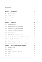
Specifications 2 1.3 Motherboard Layout 6 1.4 I/O Panel 8 Chapter 2 Installation 10 2.1 Installing the CPU 11 2.2 Installing the CPU Fan and Heatsink 14 2.3 Installing Memory Modules (DIMM) 15 2.4 Expansion Slots (PCI Express Slots) 17 2.5 Jumpers Setup 18 2.6 Onboard Headers and - ASRock B365M Pro4-F | User Manual - Page 5
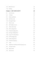
3.3.3 BIOS & Drivers 34 3.3.4 Setting 38 Chapter 4 UEFI SETUP UTILITY 39 4.1 Introduction 39 4.2 EZ Mode 40 4.3 Advanced Mode 41 4.3.1 UEFI Menu Bar 41 4.3.2 Navigation Keys 42 4.4 Main Screen 43 4.5 OC Tweaker Screen 44 4.6 Advanced Screen 54 4.6.1 CPU Configuration 55 4.6.2 - ASRock B365M Pro4-F | User Manual - Page 6
- ASRock B365M Pro4-F | User Manual - Page 7
the latest VGA cards and CPU support list on ASRock's website as well. ASRock website http://www.asrock.com. 1.1 Package Contents • ASRock B365M Pro4-F Motherboard (Micro ATX Form Factor) • ASRock B365M Pro4-F Quick Installation Guide • ASRock B365M Pro4-F Support CD • 2 x Serial ATA (SATA) Data - ASRock B365M Pro4-F | User Manual - Page 8
® Extreme Memory Profile (XMP) 2.0 • 15μ Gold Contact in DIMM Slots Expansion Slot • 2 x PCI Express 3.0 x16 Slots (PCIE1/PCIE3: single at x16 (PCIE1); dual at x16 (PCIE1) / x4 (PCIE3)) * Supports NVMe SSD as boot disks • 1 x PCI Express 3.0 x1 Slot (Flexible PCIe) • Supports AMD Quad CrossFireXTM - ASRock B365M Pro4-F | User Manual - Page 9
B365M Pro4-F • HWAEncode/Decode: AVC/H.264, HEVC/H.265 8-bit, HEVC/H.265 10-bit, VP8, VP9 8-bit, VP9 10-bit (Decode only), MPEG2, MJPEG, VC-1 (Decode only) • Three graphics output options: D-Sub, DVI-D and HDMI • Supports Triple Monitor • Supports HDMI 1.4 with max. resolution up to 4K x 2K ( - ASRock B365M Pro4-F | User Manual - Page 10
x4 (32 Gb/s)* * Supports Intel® OptaneTM Technology * Supports NVMe SSD as boot disks * Supports ASRock U.2 Kit Connector • 1 x COM Port Header • 1 x TPM Header • 1 x Chassis Intrusion and Speaker Header • 1 x CPU Fan Connector (4-pin) * The CPU Fan Connector supports the CPU fan of maximum 1A - ASRock B365M Pro4-F | User Manual - Page 11
B365M Pro4-F BIOS Feature Hardware Monitor OS Certifications • AMI UEFI Legal BIOS with multilingual GUI support • ACPI 6.0 Compliant wake up events • SMBIOS 2.7 Support • CPU, DRAM, PCH 1.0V, VCCSA, VCCST Voltage Multi- adjustment • Temperature Sensing: CPU, CPU/Water Pump, Chassis/Water Pump - ASRock B365M Pro4-F | User Manual - Page 12
1.3 Motherboard Layout USB 2.0 T: USB1 B: USB2 PS2 Keyboard /Mouse ATX12V1 CPU_FAN1 RoHS PCIe Gen3 x4 SATA3_2 B365M Pro4-F PCIE2 CMOS Battery HD_AUDIO1 1 COM1 1 CLRMOS1 1 PCIE3 TPMS1 CHA_FAN3/WP CHA_FAN2/WP 1 1 USB3_4 USB5_6 1 Intel B365 SATA3_4 BIOS ROM SATA3_1 SATA3_0 SPK_CI1 - ASRock B365M Pro4-F | User Manual - Page 13
2.0 Header (USB3_4) 18 Chassis/Water Pump Fan Connector (CHA_FAN2/WP) 19 Chassis/Water Pump Fan Connector (CHA_FAN3/WP) 20 TPM Header (TPMS1) 21 Clear CMOS Jumper (CLRMOS1) 22 COM Port Header (COM1) 23 Front Panel Audio Header (HD_AUDIO1) 24 Chassis/Water Pump Fan Connector (CHA_FAN1/WP) B365M Pro4 - ASRock B365M Pro4-F | User Manual - Page 14
)* 2 D-Sub Port 3 LAN RJ-45 Port** 4 Line In (Light Blue)*** 5 Front Speaker (Lime)*** 6 Microphone (Pink)*** No. Description 7 USB 3.2 Gen1 Ports (USB3_3_4) 8 USB Power (+5VDUAL). The USB1 is optimal for connecting the USB Type speaker and headset. ** There are two LEDs on the LAN port. Please - ASRock B365M Pro4-F | User Manual - Page 15
B365M Pro4-F *** To configure 7.1 CH HD Audio, it is required to use an HD front panel audio module and enable the multichannel audio feature through the audio driver. Please set Speaker Configuration to "7.1 Speaker"in the Realtek HD Audio Manager. Function of the Audio Ports in 7.1-channel - ASRock B365M Pro4-F | User Manual - Page 16
Pre-installation Precautions Take note of the following precautions before you install motherboard components or change any motherboard settings. • Make sure to unplug the power cord before installing or removing the motherboard components. Failure to do so may cause physical injuries and damages to - ASRock B365M Pro4-F | User Manual - Page 17
B365M Pro4-F 2.1 Installing the CPU 1. Before you insert the 1151-Pin CPU into the socket, please check if the PnP cap is on the socket, if the - ASRock B365M Pro4-F | User Manual - Page 18
4 5 12 3 English - ASRock B365M Pro4-F | User Manual - Page 19
B365M Pro4-F Please save and replace the cover if the processor is removed. The cover must be placed if you wish to return the motherboard for after service. 13 English - ASRock B365M Pro4-F | User Manual - Page 20
2.2 Installing the CPU Fan and Heatsink 1 2 CPU_FAN English 14 - ASRock B365M Pro4-F | User Manual - Page 21
B365M Pro4-F 2.3 Installing Memory Modules (DIMM) This motherboard provides four 288-pin DDR4 (Double Data Rate 4) DIMM slots, and supports Dual Channel Memory Technology. 1. For dual channel configuration, you always need to install identical (the same brand, speed, size and chip-type) DDR4 DIMM - ASRock B365M Pro4-F | User Manual - Page 22
1 2 3 16 English - ASRock B365M Pro4-F | User Manual - Page 23
B365M Pro4-F 2.4 Expansion Slots (PCI Express Slots) There are 3 PCI Express slots on the motherboard. Before installing an expansion card, x4 For a better thermal environment, please connect a chassis fan to the motherboard's chassis fan connector (CHA_FAN1/WP, CHA_FAN2/WP or CHA_FAN3/WP) when - ASRock B365M Pro4-F | User Manual - Page 24
the pins on CLRMOS1 for 5 seconds. However, please do not clear the CMOS right after you update the BIOS. If you need to clear the CMOS when you just finish updating the BIOS, you must boot up the system first, and then shut it down before you do the clear-CMOS action - ASRock B365M Pro4-F | User Manual - Page 25
B365M Pro4-F 2.6 Onboard Headers and Connectors Onboard headers and connectors are NOT jumpers. Do NOT place jumper caps over these headers and connectors. Placing jumper caps over the headers and connectors will cause permanent damage to the motherboard. System Panel Header (9-pin PANEL1) (see - ASRock B365M Pro4-F | User Manual - Page 26
USB5_6) (see p.6, No. 16) USB_PWR PP+ GND DUMMY 1 GND P+ PUSB_PWR There is one header on this motherboard. This USB 2.0 header can support two ports. USB 3.2 Gen1 Header (19-pin USB3_5_6) (see p.6, No. 7) Vbus IntA_PA_SSRXIntA_PA_SSRX+ GND IntA_PA_SSTXIntA_PA_SSTX+ GND IntA_PA_DIntA_PA_D+ Vbus - ASRock B365M Pro4-F | User Manual - Page 27
B365M Pro4-F 1. High Definition Audio supports Jack Sensing, but the panel wire on the chassis must support HDA to function correctly. Please follow the instructions in our manual and chassis manual to install your system. 2. If you use an AC'97 audio panel, please install it to the front panel - ASRock B365M Pro4-F | User Manual - Page 28
along Pin 1 and Pin 13. 8 5 This motherboard pro- vides a 8-pin ATX 12V 4 1 power connector. To use a 4-pin ATX power supply, please plug it along Pin 1 and Pin 5. RRXD1 DDTR#1 DDSR#1 CCTS#1 1 RRI#1 RRTS#1 GND TTXD1 DDCD#1 This COM1 header supports a serial port module. This connector - ASRock B365M Pro4-F | User Manual - Page 29
B365M Pro4-F 2.7 CrossFireXTM and Quad CrossFireXTM Operation Guide This motherboard supports CrossFireXTM and Quad CrossFireXTM that to enable CrossFireXTM. Please refer to AMD graphics card manuals for detailed installation guide. 2.7.1 Installing Two CrossFireXTM-Ready Graphics Cards Step 1 - ASRock B365M Pro4-F | User Manual - Page 30
Step 3 Connect a VGA cable or a DVI cable to the monitor connector or the DVI connector of the graphics card that is inserted to PCIE1 slot. 24 English - ASRock B365M Pro4-F | User Manual - Page 31
B365M Pro4-F 2.7.2 Driver Installation and Setup Step 1 Power on your computer and boot into OS. Step 2 Remove the AMD drivers if you have any VGA drivers installed - ASRock B365M Pro4-F | User Manual - Page 32
2.8 M.2_SSD (NGFF) Module Installation Guide (M2_1) The M.2, also known as the Next Generation Form Factor (NGFF), is a small size and versatile card edge connector that aims to replace mPCIe and mSATA. The Ultra M.2 Socket (M2_1) supports M Key type 2242/2260/2280 M.2 PCI Express module up to Gen3 - ASRock B365M Pro4-F | User Manual - Page 33
C B A C B A C B A B365M Pro4-F Step 3 Move the standoff based on the module type and protective film on the nut to be used. Hand tighten the standoff into the desired nut location on the motherboard. Step 5 Gently insert the M.2 (NGFF) SSD module into the M.2 slot. Please be aware that the - ASRock B365M Pro4-F | User Manual - Page 34
(MZHPV512HDGL) SM951 (NVME) XP941-512G (MZHPU512HCGL) SD6PP4M-128G SD6PP4M-256G TM8FP2240G0C101 TM8FP2480GC110 WDS256G1X0C-00ENX0 (NVME) WDS512G1X0C-00ENX0 (NVME) For the latest updates of M.2_SSD (NFGG) module support list, please visit our website for details: http://www.asrock.com English 28 - ASRock B365M Pro4-F | User Manual - Page 35
B365M Pro4-F Chapter 3 Software and Utilities Operation 3.1 Installing Drivers The Support CD that comes with the motherboard contains necessary drivers and useful utilities that enhance the motherboard's features. Running The Support CD To begin using the support CD, insert the CD into your CD-ROM - ASRock B365M Pro4-F | User Manual - Page 36
and improved utilities. 3.2.1 Installing A-Tuning A-Tuning can be downloaded from ASRock Live Update & APP Shop. After the installation, you will find , A-Tuning main menu will pop up. 3.2.2 Using A-Tuning There are four sections in A-Tuning main menu: Operation Mode, System Info, FAN-Tastic Tuning - ASRock B365M Pro4-F | User Manual - Page 37
Info View information about the system. *The System Browser tab may not appear for certain models. B365M Pro4-F FAN-Tastic Tuning Configure up to five different fan speeds using the graph. The fans will automatically shift to the next speed level when the assigned temperature is met. English 31 - ASRock B365M Pro4-F | User Manual - Page 38
Settings Configure ASRock A-Tuning. Click to select "Auto run at Windows Startup" if you want A-Tuning to be launched when you start up the Windows operating system. 32 English - ASRock B365M Pro4-F | User Manual - Page 39
B365M Pro4-F 3.3 ASRock Live Update & APP Shop The ASRock Live Update & APP Shop is an online store for purchasing and downloading software applications for your ASRock computer. You can quickly and easily install various apps and support utilities. With ASRock Live Update & APP Shop, you can - ASRock B365M Pro4-F | User Manual - Page 40
on the right. Please scroll up and down to see more apps listed. You can check the price of the app and whether you have already intalled it or not. - The red icon displays the price or "Free" if the app is free of charge. - The green "Installed" icon means the app - ASRock B365M Pro4-F | User Manual - Page 41
B365M Pro4-F Step 3 If you want to install the app, click on the red icon to start downloading. Step 4 When installation completes, you can find the green " - ASRock B365M Pro4-F | User Manual - Page 42
Upgrading an App You can only upgrade the apps you have already installed. When there is an available new version for your app, you will find the mark of "New Version" appears below the installed app icon. Step 1 Click on the app icon to see more details. Step 2 Click on the yellow icon to start - ASRock B365M Pro4-F | User Manual - Page 43
B365M Pro4-F 3.3.3 BIOS & Drivers Installing BIOS or Drivers When the "BIOS & Drivers" tab is selected, you will see a list of recommended or critical updates for the BIOS or drivers. Please update them all soon. Step 1 Please check the item information before update. Click on Step 2 to see more - ASRock B365M Pro4-F | User Manual - Page 44
3.3.4 Setting In the "Setting" page, you can change the language, select the server location, and determine if you want to automatically run the ASRock Live Update & APP Shop on Windows startup. 38 English - ASRock B365M Pro4-F | User Manual - Page 45
B365M Pro4-F Chapter 4 UEFI SETUP UTILITY 4.1 Introduction This section explains how to use the UEFI SETUP UTILITY to configure your system. You may run the UEFI SETUP - ASRock B365M Pro4-F | User Manual - Page 46
Mode screen appears when you enter the BIOS setup program by default. EZ mode is a dashboard which contains multiple readings of the system's current status. You can check the most crucial information of your system, such as CPU speed, DRAM frequency, SATA information, fan speed, etc. Press or - ASRock B365M Pro4-F | User Manual - Page 47
B365M Pro4-F 4.3 Advanced Mode The Advanced Mode provides more options to configure the BIOS settings. Refer to the following sections for bar with the following selections: Main For setting system time/date information OC Tweaker For overclocking configurations Advanced For advanced system - ASRock B365M Pro4-F | User Manual - Page 48
4.3.2 Navigation Keys Use < > key or < > key to choose among the selections on the menu bar, and use < > key or < > key to move the cursor up or down to select items, then press to get into the sub screen. You can also use the mouse to click your required item. Please check the following - ASRock B365M Pro4-F | User Manual - Page 49
B365M Pro4-F 4.4 Main Screen When you enter the UEFI SETUP UTILITY, the Main screen will appear and display the system overview. My Favorite Display your collection of BIOS items. Press F5 to add/remove your favorite items. 43 English - ASRock B365M Pro4-F | User Manual - Page 50
In the OC Tweaker screen, you can set up overclocking features. Because the UEFI software is constantly being updated on your screen. CPU Configuration Boot Performance Mode Select the performance state that the BIOS will set before OS handoff. FCLK Frequency Configure the FCLK Frequency. AVX Ratio - ASRock B365M Pro4-F | User Manual - Page 51
B365M Pro4-F of the BCLK frequency when calculating the CPU V/F curves. This is ideal for BCLK the highest performance state. Intel Speed Shift Technology Enable/Disable Intel Speed Shift Technology support. Enabling will expose the CPPC v2 interface to allow for hardware controlled P-states. - ASRock B365M Pro4-F | User Manual - Page 52
Setting Load XMP settings to overclock the memory and perform beyond standard specifications. DRAM Reference Clock Select Auto for optimized settings. DRAM Frequency If [Auto] is selected, the motherboard will detect the memory module(s) inserted and assign the appropriate frequency automatically - ASRock B365M Pro4-F | User Manual - Page 53
B365M Pro4-F Command Rate (CR) The delay between when a memory chip is selected and when the first active command can be issued. Secondary Timing Write Recovery Time ( - ASRock B365M Pro4-F | User Manual - Page 54
tREFI Configure refresh cycles at an average periodic interval. tCKE Configure the period of time the DDR4 initiates a minimum of one refresh command internally once it enters Self-Refresh mode. Turn Around Timing tRDRD_sg Configure between module read to read delay. tRDRD_dg Configure between - ASRock B365M Pro4-F | User Manual - Page 55
A. IO-L (CH B) Configure IO latency for channel B. IO-L Offset (CH A) Configure IO latency offset for channel A. IO-L Offset (CH B) Configure IO latency offset for channel B. B365M Pro4-F 49 English - ASRock B365M Pro4-F | User Manual - Page 56
die termination resistors' WR for channel B2. ODT NOM (A1) Use this to change ODT (CH A1) Auto/Manual settings. The default is [Auto]. ODT NOM (A2) Use this to change ODT (CH A2) Auto/Manual settings. The default is [Auto]. ODT NOM (B1) Use this to change ODT (CH B1) Auto - ASRock B365M Pro4-F | User Manual - Page 57
B365M Pro4-F ODT PARK (B2) Configure the memory on die termination resistors' PARK for channel B2. COMP Setting RCOMP0: DQ ODT (Read) Default is 121. RCOMP1: DQ / - ASRock B365M Pro4-F | User Manual - Page 58
. MRS tCCD_L Configure the tCL for Memory MRS MR6. Advanced Setting ASRock Timing Optimization Configure the fast path through the MRC. Realtime Memory Timing timing changes after MRC_DONE. Command Tristate Configure the Command Tristate Support. Exit On Failure Configure the Exit On Failure for MRC - ASRock B365M Pro4-F | User Manual - Page 59
B365M Pro4-F CPU Load-Line Calibration CPU Load-Line Calibration helps prevent CPU voltage droop when the system is under heavy loading. GT Voltage Configure the voltage - ASRock B365M Pro4-F | User Manual - Page 60
UEFI setup utility. Full HD UEFI When [Auto] is selected, the resolution will be set to 1920 x 1080 if the monitor supports Full HD resolution. If the monitor does not support Full HD resolution, then the resolution will be set to 1024 x 768. When [Disable] is selected, the resolution will be set - ASRock B365M Pro4-F | User Manual - Page 61
B365M Pro4-F Intel Hyper Threading Technology Intel Hyper Threading Technology allows multiple threads to run on each core, so that the overall performance on threaded software is improved. Active Processor Cores Select the number of cores to enable in each processor package. CPU C States Support - ASRock B365M Pro4-F | User Manual - Page 62
CPU, PCIe, Memory, Graphics C State Support for power saving. CFG Lock This item allows you to disable or enable better performance. Software Guard Extensions (SGX) Intel SGX is a set of new CPU instructions that can be used by applications to set aside private regions of code and data. 56 English - ASRock B365M Pro4-F | User Manual - Page 63
4.6.2 Chipset Configuration B365M Pro4-F Primary Graphics Adapter Select a primary VGA. Above 4G Decoding Enable or disable 64bit capable Devices to be decoded in Above 4G Address Space (only if the system supports 64 bit PCI decoding). VT-d Intel® Virtualization Technology for Directed I/O helps - ASRock B365M Pro4-F | User Manual - Page 64
This option enables/disables the control of ASPM on CPU side of the DMI Link. PCH DMI ASPM Support This option enables/disables the ASPM support for all PCH DMI devices. Share Memory Configure the size of memory that is allocated to the integrated graphics processor when the system boots up. - ASRock B365M Pro4-F | User Manual - Page 65
B365M Pro4-F WAN Radio Enable/disable the WiFi module's connectivity. Bluetooth Enable/disable the bluetooth. Deep Sleep Configure deep sleep mode for power saving when the computer is shut down. Restore on AC/Power Loss Select the power state after a - ASRock B365M Pro4-F | User Manual - Page 66
Link Power Management allows SATA devices to enter a low power state during periods of inactivity to save power. It is only supported by AHCI mode. Hard Disk S.M.A.R.T. S.M.A.R.T stands for Self-Monitoring, Analysis, and Reporting Technology. It is a monitoring system for computer hard disk - ASRock B365M Pro4-F | User Manual - Page 67
4.6.4 Super IO Configuration B365M Pro4-F Serial Port Enable or disable the Serial port. Serial Port Address Select the address of the Serial port. PS2 Y-Cable Enable the PS2 Y-Cable or set this option to Auto. 61 English - ASRock B365M Pro4-F | User Manual - Page 68
4.6.5 ACPI Configuration Suspend to RAM Select disable for ACPI suspend type S1. It is recommended to select auto for ACPI S3 power saving. ACPI HEPT Table Enable the High Precision Event Timer for better performance. PS/2 Keyboard Power On Allow the system to be waked up by a PS/2 Keyboard. PCIE - ASRock B365M Pro4-F | User Manual - Page 69
B365M Pro4-F USB Keyboard/Remote Power On Allow the system to be waked up by an USB keyboard or remote controller. USB Mouse Power On Allow the system to be waked up by an USB mouse. 63 English - ASRock B365M Pro4-F | User Manual - Page 70
for USB 2.0 devices. If you encounter USB compatibility issues it is recommended to disable legacy USB support. Select UEFI Setup Only to support USB devices under the UEFI setup and Windows/Linux operating systems only. PS/2 Simulator Enable PS/2 Simulator. This should be enabled for the complete - ASRock B365M Pro4-F | User Manual - Page 71
4.6.7 Trusted Computing B365M Pro4-F Security Device Support Enable or disable BIOS support for security device. English 65 - ASRock B365M Pro4-F | User Manual - Page 72
4.7 Tools UEFI Tech Service Contact ASRock Tech Service if you are having trouble with your PC. Please setup network configuration before using UEFI Tech Service. SSD Secure Erase Tool Use this tool to securely erase SSD. Instant Flash Save UEFI files in your USB storage device and run Instant Flash - ASRock B365M Pro4-F | User Manual - Page 73
Network Configuration Use this to configure internet connection settings for Internet Flash. B365M Pro4-F Internet Setting Enable or disable sound effects in the setup utility. UEFI Download Server Select a server to download the UEFI firmware. English 67 - ASRock B365M Pro4-F | User Manual - Page 74
the status of the hardware on your system, including the parameters of the CPU temperature, motherboard temperature, fan speed and voltage. Fan Tuning Measure Fan Min Duty Cycle. Fan-Tastic Tuning Select a fan mode for CPU Fan, or choose Customize to set 5 CPU temperatures and assign a respective - ASRock B365M Pro4-F | User Manual - Page 75
B365M Pro4-F CPU Fan 2 Control Mode Select PWM mode or DC mode for CPU fan 2. CPU Fan 2 Setting Select a fan mode for CPU Fan 2, or choose Customize to set 5 CPU temperatures and assign a respective fan speed for each temperature. CPU Fan 2 Temp Source Select a fan temperature source for CPU Fan 2. - ASRock B365M Pro4-F | User Manual - Page 76
or DC mode for Chassis Fan 3. Chassis Fan 3 Setting Select a fan mode for Chassis Fan 3, or choose Customize to set 5 CPU temperatures and assign a respective fan speed for each temperature. Chassis Fan 3 Temp Source Select a fan temperature source for Chassis Fan 3. Chassis Fan 3 Step Up Set the - ASRock B365M Pro4-F | User Manual - Page 77
B365M Pro4-F 4.9 Security Screen In this section you may set or change the supervisor blank and press enter to remove the password. Secure Boot Use this item to enable or disable support for Secure Boot. Intel(R) Platform Trust Technology Enable/disable Intel PTT in ME. Disable this option to - ASRock B365M Pro4-F | User Manual - Page 78
priority. Fast Boot Fast Boot minimizes your computer's boot time. In fast mode you may not boot from an USB storage device. The VBIOS must support UEFI GOP if you are using an external graphics card. Please notice that Ultra Fast mode will boot so fast that the only way to - ASRock B365M Pro4-F | User Manual - Page 79
B365M Pro4-F Full Screen Logo Enable to display the boot logo or disable a number of times the system automatically restores the default settings. CSM (Compatibility Support Module) CSM Enable to launch the Compatibility Support Module. Please do not disable unless you're running a WHCK test. Launch - ASRock B365M Pro4-F | User Manual - Page 80
Launch Storage OpROM Policy Select UEFI only to run those that support UEFI option ROM only. Select Legacy only to run those that support legacy option ROM only. Select Do not launch to not execute both legacy and UEFI option ROM. Other PCI Device ROM Priority For PCI devices - ASRock B365M Pro4-F | User Manual - Page 81
4.11 Exit Screen B365M Pro4-F Save Changes and Exit When you select this option the following message, "Save configuration changes and exit setup?" will pop out. Select [OK] to save - ASRock B365M Pro4-F | User Manual - Page 82
dealer for further information. For technical questions, please submit a support request form at https://event.asrock.com/tsd.asp ASRock Incorporation 2F., No.37, Sec. 2, Jhongyang S. Rd., Beitou District, Taipei City 112, Taiwan (R.O.C.) ASRock EUROPE B.V. Bijsterhuizen 11-11 6546 AR Nijmegen The - ASRock B365M Pro4-F | User Manual - Page 83
Per FCC Part 2 Section 2.1077(a) Responsible Party Name: ASRock Incorporation Address: 13848 Magnolia Ave, Chino, CA91710 Phone/Fax No: +1-909-590-8308/+1-909-590-1026 hereby declares that the product Product Name : Motherboard Model Number : B365M Pro4-F Conforms to the following speci cations: FCC - ASRock B365M Pro4-F | User Manual - Page 84
EU Declaration of Conformity For the following equipment: Motherboard (Product Name) B365M Pro4-F / ASRock (Model Designation / Trade Name) ASRock Incorporation (Manufacturer Name) 2F., No.37, Sec. 2, Jhongyang S. Rd., Beitou District, Taipei City 112, Taiwan (R.O.C.) (Manufacturer Address) ڛ
-
 1
1 -
 2
2 -
 3
3 -
 4
4 -
 5
5 -
 6
6 -
 7
7 -
8
-
9
-
10
-
11
-
12
-
13
-
14
-
15
-
16
-
17
-
18
-
19
-
20
-
21
-
22
-
23
-
24
-
25
-
26
-
27
-
28
-
29
-
30
-
31
-
32
-
33
-
34
-
35
-
36
-
37
-
38
-
39
-
40
-
41
-
42
-
43
-
44
-
45
-
46
-
47
-
48
-
49
-
50
-
51
-
52
-
53
-
54
-
55
-
56
-
57
-
58
-
59
-
60
-
61
-
62
-
63
-
64
-
65
-
66
-
67
-
68
-
69
-
70
-
71
-
72
-
73
-
74
-
75
-
76
-
77
-
78
-
79
-
80
-
81
-
82
-
83
-
84
 |
 |