ASRock Fatal1ty X299 Gaming K6 Quick Installation Guide
ASRock Fatal1ty X299 Gaming K6 Manual
 |
View all ASRock Fatal1ty X299 Gaming K6 manuals
Add to My Manuals
Save this manual to your list of manuals |
ASRock Fatal1ty X299 Gaming K6 manual content summary:
- ASRock Fatal1ty X299 Gaming K6 | Quick Installation Guide - Page 1
documentation are furnished for informational use only and subject to change without notice, and should not be constructed as a commitment by ASRock. ASRock assumes no responsibility for any errors or omissions that may appear in this documentation. With respect to the contents of this documentation - ASRock Fatal1ty X299 Gaming K6 | Quick Installation Guide - Page 2
replaced if the goods fail to be of acceptable quality and the failure does not amount to a major failure. If you require assistance please call ASRock Tel : +886-2-28965588 ext.123 (Standard International call charges apply) - ASRock Fatal1ty X299 Gaming K6 | Quick Installation Guide - Page 3
Fatal1ty Story Who knew that at age 19, I would be a World Champion PC gamer. When I was 13, I actually played competitive billiards in professional tournaments and won four or five games off guys who played at the highest level. I actually thought of making a career of it, but at that young age - ASRock Fatal1ty X299 Gaming K6 | Quick Installation Guide - Page 4
all about getting the computer processing faster and allowing more fluid movement around the maps. My vision for Fatal1ty hardware is to allow gamers to focus on the game without worrying about their equipment, something I've preached since I began competing. I don't want to worry about my equipment - ASRock Fatal1ty X299 Gaming K6 | Quick Installation Guide - Page 5
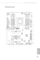
Fatal1ty X299 Gaming K6 Series Motherboard Layout 12 3 4 56 7 USB 2.0 T: USB3 B: USB4 PS2 Keyboard /Mouse CLRC BTN1 ATXPWR1 CPU_FAN1 1 8 RGB_LED2 9 10 11 1 1 12 USB3_7_8 SATA3_0_1 M2_2 PCIE2 X299 Gaming K6 PCIE3 M2_3 AUDIO CODEC PCIE4 HD_AUDIO1 1 CLRMOS1 RGB_LED1 1 1 1 T B1 PCIE5 - ASRock Fatal1ty X299 Gaming K6 | Quick Installation Guide - Page 6
x 288-pin DDR4 DIMM Slots (DDR4_C2, DDR4_D2) 6 2 x 288-pin DDR4 DIMM Slots (DDR4_C1, DDR4_D1) 7 CPU Fan Connector (CPU_FAN1) 8 RGB LED Header (RGB_LED2) 9 ATX Power Connector (ATXPWR1) 10 Virtual RAID On CPU Header (VROC1) 11 USB 3.0 Header (USB3_5_6) 12 USB 3.0 Header (USB3_7_8) 13 SATA3 Connectors - ASRock Fatal1ty X299 Gaming K6 | Quick Installation Guide - Page 7
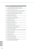
I/O Panel 1 2 Fatal1ty X299 Gaming K6 Series 3 4 57 68 17 16 15 No. Description 1 USB 2.0 Port (USB_3) 2 Fatal1ty Mouse Port (USB_4) 3 LAN RJ-45 Port (Intel® I211AT)* 4 LAN RJ-45 Port (Intel® I219V)* 5 Central / Bass (Orange) 6 Rear Speaker (Black) 7 Line In (Light Blue) 8 - ASRock Fatal1ty X299 Gaming K6 | Quick Installation Guide - Page 8
** If you use a 2-channel speaker, please connect the speaker's plug into "Front Speaker Jack". See the table below for connection details in accordance with the type of speaker you use. Audio Output Channels 2 4 6 8 Front Speaker (No. 8) V V V V Rear Speaker (No. 6) -V V V Central / Bass (No. - ASRock Fatal1ty X299 Gaming K6 | Quick Installation Guide - Page 9
cards and CPU support list on ASRock's website as well. ASRock website http://www.asrock.com. 1.1 Package Contents • ASRock Fatal1ty X299 Gaming K6 Series Motherboard (ATX Form Factor) • ASRock Fatal1ty X299 Gaming K6 Series Quick Installation Guide • ASRock Fatal1ty X299 Gaming K6 Series Support CD - ASRock Fatal1ty X299 Gaming K6 | Quick Installation Guide - Page 10
Max Technology 3.0 * Please note that the 4-Core processors only support Intel® Turbo Boost Technology 2.0. • Supports ASRock Hyper BCLK Engine III Chipset • Intel® X299 Memory • Quad Channel DDR4 Memory Technology • 8 x DDR4 DIMM Slots • Supports DDR4 4400+(OC)*/4266(OC)/4133(OC)/4000 (OC)/3866 - ASRock Fatal1ty X299 Gaming K6 | Quick Installation Guide - Page 11
Fatal1ty X299 Gaming K6 Series ** If PCIE4 slot is occupied, M2_2 slot will support M.2 PCI Express module up to Gen3 x2 (16 Gb/s). • Supports AMD Quad CrossFireXTM, 3-Way CrossFireXTM and CrossFireXTM *** • Supports NVIDIA® Quad SLITM, 3-Way SLITM and SLITM*** *** 3-Way CrossFireXTM and 3-Way - ASRock Fatal1ty X299 Gaming K6 | Quick Installation Guide - Page 12
Gen3 x4 (32 Gb/s)** ** If PCIE4 slot is occupied, M2_2 slot will support M.2 PCI Express module up to Gen3 x2 (16 Gb/s). ** Supports Intel® OptaneTM Technology ** Supports NVMe SSD as boot disks ** Supports ASRock U.2 Kit Connector • 1 x Virtual RAID On CPU Header • 1 x TPM Header • 1 x Power LED - ASRock Fatal1ty X299 Gaming K6 | Quick Installation Guide - Page 13
Fatal1ty X299 Gaming K6 Series BIOS Feature • 1 x CPU Fan Connector (4-pin) * The CPU Fan Connector supports the CPU fan of maximum 1A (12W) fan power. • 1 x CPU Optional/Water Pump Fan Connector (4-pin) * The CPU Optional/Water Pump Fan supports . • 1 x 24 pin ATX Power Connector (Hi-Density Power - ASRock Fatal1ty X299 Gaming K6 | Quick Installation Guide - Page 14
• FCC, CE • ErP/EuP ready (ErP/EuP ready power supply is required) * For detailed product information, please visit our website: http://www.asrock.com Please realize that there is a certain risk involved with overclocking, including adjusting the setting in the BIOS, applying Untied Overclocking - ASRock Fatal1ty X299 Gaming K6 | Quick Installation Guide - Page 15
Fatal1ty X299 Gaming K6 Series Chapter 2 Installation This is an ATX form factor motherboard. Before you install the motherboard, study the configuration of your chassis to ensure that the motherboard fits into it. Pre-installation Precautions - ASRock Fatal1ty X299 Gaming K6 | Quick Installation Guide - Page 16
situation is found. Otherwise, the CPU will be seriously damaged. 2. Unplug all power cables before installing the CPU. CAUTION: Please note that X299 platform is only compatible with the LGA 2066 socket, which is incompatible with the LGA 2011-3 socket (for X99 platform). 1 A B A 2 B 12 English - ASRock Fatal1ty X299 Gaming K6 | Quick Installation Guide - Page 17
Fatal1ty X299 Gaming K6 Series A 3 B 4 5 13 English - ASRock Fatal1ty X299 Gaming K6 | Quick Installation Guide - Page 18
6 A B 7 A B 8 Please save and replace the cover if the processor is removed. The cover must be placed if you wish to return the motherboard for after service. 14 English - ASRock Fatal1ty X299 Gaming K6 | Quick Installation Guide - Page 19
Fatal1ty X299 Gaming K6 Series 2.2 Installing the CPU Fan and Heatsink 1 2 CPU_FAN 15 English - ASRock Fatal1ty X299 Gaming K6 | Quick Installation Guide - Page 20
2.3 Installation of Memory Modules (DIMM) This motherboard provides eight 288-pin DDR4 (Double Data Rate 4) DIMM slots, and supports Quad Channel Memory Technology. 1. For quad channel configuration, you always need to install identical (the same brand, speed, size and chip-type) DDR4 DIMM pairs. 2. - ASRock Fatal1ty X299 Gaming K6 | Quick Installation Guide - Page 21
Fatal1ty X299 Gaming K6 Series • For CPU with 16 PCIe lanes, please install the memory modules on DDR4_C1, C2, D1 and D2 only. 1 2 3 17 English - ASRock Fatal1ty X299 Gaming K6 | Quick Installation Guide - Page 22
lanes, PCIE1/PCIE2/PCIE3/PCIE5 will run at x16/x4/ x0/x0 or x8/x4/x8/x0. * If PCIE4 slot is occupied, M2_2 slot will support M.2 PCI Express module up to Gen3 x2 (16 Gb/s). PCIe Slot Configurations (For CPU with 44 PCIe lanes) Single Graphics Card PCIE1 x16 PCIE2 N/A PCIE3 - ASRock Fatal1ty X299 Gaming K6 | Quick Installation Guide - Page 23
Fatal1ty X299 Gaming K6 Series PCIe Slot Configurations (For CPU with 28 PCIe lanes) PCIE1 PCIE2 PCIE3 Single Graphics Card x16 N/A N/A PCIE4 N/A PCIE5 N/A Two Graphics Cards in CrossFireXTM or - ASRock Fatal1ty X299 Gaming K6 | Quick Installation Guide - Page 24
2.5 Jumpers Setup The illustration shows how jumpers are setup. When the jumper cap is placed on the pins, the jumper is "Short". If no jumper cap is placed on the pins, the jumper is "Open". The illustration shows a 3-pin jumper whose pin1 and pin2 are "Short" when a jumper cap is placed on these 2 - ASRock Fatal1ty X299 Gaming K6 | Quick Installation Guide - Page 25
Fatal1ty X299 Gaming K6 Series 2.6 Onboard Headers and Connectors Onboard headers and connectors are NOT jumpers. Do NOT place jumper caps over these headers and connectors. Placing jumper caps - ASRock Fatal1ty X299 Gaming K6 | Quick Installation Guide - Page 26
. 14) (SATA3_4_5: see p.1, No. 15) (SATA3_6_7: see p.1, No. 16) SATA3_6 SATA3_4 SATA3_2 SATA3_0 SATA3_7 SATA3_5 SATA3_3 SATA3_1 These eight SATA3 connectors support SATA data cables for internal storage devices with up to 6.0 Gb/s data transfer rate. * If M2_1 is occupied by a SATA-type M.2 device - ASRock Fatal1ty X299 Gaming K6 | Quick Installation Guide - Page 27
Fatal1ty X299 Gaming K6 Series USB 3.0 Headers (19-pin USB3_5_6) (see p.1, No. 11) (19-pin High Definition Audio supports Jack Sensing, but the panel wire on the chassis must support HDA to function correctly. Please follow the instructions in our manual and chassis manual to install your system - ASRock Fatal1ty X299 Gaming K6 | Quick Installation Guide - Page 28
. If you plan to connect a 3-Pin CPU water cooler fan, please connect it to Pin 1-3. ATX Power Connector (24-pin ATXPWR1) (see p.1, No. 9) 12 24 1 13 This motherboard provides a 24-pin ATX power connector. To use a 20-pin ATX power supply, please plug it along Pin 1 and Pin 13. English 24 - ASRock Fatal1ty X299 Gaming K6 | Quick Installation Guide - Page 29
Fatal1ty X299 Gaming K6 Series ATX 12V Power Connector (8-pin ATX12V1) (see p.1, No. 3) 8 5 4 1 8-pin ATX 12V power connector. To use a 4-pin ATX power supply, please plug it along Pin 1 and Pin 5. This connector supports Trusted Platform further instructions on these two headers. English 25 - ASRock Fatal1ty X299 Gaming K6 | Quick Installation Guide - Page 30
of operation: SKU HW key required Key features Pass-thru Not needed • Pass-thru only (no RAID) • 3rd party NVMe SSD support • LED Management • Hot Plug Support • RAID 0 support for Intel Fultondale NVMe SSDs Standard Standard Key • Pass-thru SKU features • RAID 0, 1, 10 • 3rd party NVMe SSD - ASRock Fatal1ty X299 Gaming K6 | Quick Installation Guide - Page 31
Fatal1ty X299 Gaming K6 Series 2.7 Smart Switches The motherboard has a smart switch: Clear CMOS Switch, allowing users to clear the CMOS values. Clear CMOS Switch (CLRCBTN) (see p.3, No. 16) - ASRock Fatal1ty X299 Gaming K6 | Quick Installation Guide - Page 32
. Debug is used to provide code information, which makes troubleshooting even easier. Please see the diagrams below for reading the Dr. Debug codes. Code Description 00 Please check if the CPU is installed correctly and then clear CMOS. 0d Problem related to memory, VGA card or other devices - ASRock Fatal1ty X299 Gaming K6 | Quick Installation Guide - Page 33
Fatal1ty X299 Gaming K6 Series b4 Problem related to USB devices. Please try removing all USB devices. b7 Problem related to memory. Please re-install the CPU and memory then clear CMOS. If the problem still exists, please install only one memory module or try using other memory modules. d6 - ASRock Fatal1ty X299 Gaming K6 | Quick Installation Guide - Page 34
2.9 M.2_SSD (NGFF) Module Installation Guide The M.2, also known as the Next Generation Form SATA3_4, SATA3_5, SATA3_6 and SATA3_7 will be disabled. * If PCIE4 slot is occupied, M2_2 slot will support M.2 PCI Express module up to Gen3 x2 (16 Gb/s). Installing the M.2_SSD (NGFF) Module The following - ASRock Fatal1ty X299 Gaming K6 | Quick Installation Guide - Page 35
E D C B A E D C B A C B A E D C B A E D NUT2 NUT1 Fatal1ty X299 Gaming K6 Series Step 3 Move the standoff based on the module type and length. The standoff is placed at the nut location D by default. Skip Step 3 and 4 - ASRock Fatal1ty X299 Gaming K6 | Quick Installation Guide - Page 36
M.2_SSD (NGFF) Module Support List Vendor ADATA ADATA ADATA ADATA ADATA ADATA ADATA Crucial Crucial Intel Intel Intel Kingston Kingston OCZ Plextor Plextor Plextor Plextor Plextor Plextor Samsung Samsung - ASRock Fatal1ty X299 Gaming K6 | Quick Installation Guide - Page 37
Fatal1ty X299 Gaming K6 Series WD SATA3 WDS100T1B0B-00AS40 WD SATA3 WDS240G1G0B-00RC30 WD PCIe3 x4 WDS256G1X0C-00ENX0 (NVME) WD PCIe3 x4 WDS512G1X0C-00ENX0 (NVME) For the latest updates of M.2_SSD (NFGG) module support list, please visit our website for details: http://www.asrock.com - ASRock Fatal1ty X299 Gaming K6 | Quick Installation Guide - Page 38
ASRock RGB LED ASRock 1 12V G RGB_LED2 R B 1 FATAL TY RGB_LED1 1 12V G R B X299 Gaming K6 1 B 12V G R 1. Never install the RGB LED cable in the wrong orientation come with the package. 2. The RGB LED header supports standard 5050 RGB LED strip (12V/G/R/B), with a maximum power rating of 3A - ASRock Fatal1ty X299 Gaming K6 | Quick Installation Guide - Page 39
Utility Now you can adjust the RGB LED color through the ASRock RGB LED utility. Download this utility from the ASRock Live Update & APP Shop and start coloring your PC style your way! Drag the tab to customize your preference. Toggle on/off the RGB LED - ASRock Fatal1ty X299 Gaming K6 | Quick Installation Guide - Page 40
und Prozessoren auf der ASRock-Webseite: ASRock-Website http://www.asrock.com. 1.1 Lieferumfang • ASRock-Motherboard der Fatal1ty X299 Gaming K6 Series (ATX-Formfaktor) • Schnellinstallationsanleitung zur ASRock Fatal1ty X299 Gaming K6 Series • Support-CD zur ASRock Fatal1ty X299 Gaming K6 Series - ASRock Fatal1ty X299 Gaming K6 | Quick Installation Guide - Page 41
Fatal1ty X299 Gaming K6 Series 1.2 Technische Daten Plattform Prozessor Chipsatz • ATX-Formfaktor • 8-Layer-PCB • Unterstützt Prozessoren der Informationen finden Sie in der Speicherkompatibilitätsliste auf der ASRock-Webseite. (http://www.asrock.com/) • Unterstützt Non-ECC-RDIMM (Registered - ASRock Fatal1ty X299 Gaming K6 | Quick Installation Guide - Page 42
ützt PXE • 1 x PS/2-Maus-/Tastaturanschluss • 1 x Optischer SPDIF-Ausgang • 4 x USB-2.0-Ports (unterstützt Schutz gegen elektrostatische Entladung) * 1 x Fatal1ty-Mausanschluss (USB 2.0) ist inklusive • 1 x USB 3.1-Typ-A-Port (10 Gb/s) (ASMedia ASM3142) (unterstützt Schutz gegen elektrostatische - ASRock Fatal1ty X299 Gaming K6 | Quick Installation Guide - Page 43
Fatal1ty X299 Gaming K6 Series Speicher Anschluss • 1 x USB 3.1-Typ-C-Port (10 Gb/s) (ASMedia ASM3142) (unterst Gb/s). ** Unterstützt Intel® OptaneTM-Technologie ** Unterstützt NVMe-SSD als Bootplatte ** Unterstützt ASRock U.2-Kit • 1 x Virtual RAID an der CPU-Stiftleiste • 1 x TPM-Stiftleiste • 1 - ASRock Fatal1ty X299 Gaming K6 | Quick Installation Guide - Page 44
A (18 W). * CHA_FAN1 und CHA_FAN2 können automatisch erkennen, ob ein 3- oder 4-poliger Lüfter verwendet wird. • 1 x 24-poliger ATX-Netzanschluss (hochdichter Netzanschluss). • 1 x 8-poliger 12-V-Netzanschluss (hochdichter Netzanschluss) • 1 x Audioanschluss an der Frontblende (15μ goldene Audioan - ASRock Fatal1ty X299 Gaming K6 | Quick Installation Guide - Page 45
Fatal1ty X299 Gaming K6 Series Hardwareüberwachung • Temperaturerkennung: CPU-, Optionale-CPU-/Wasserpumpen-, Geh -Netzteil erforderlich) * Detaillierte Produktinformationen finden Sie auf unserer Webseite: http://www.asrock.com Bitte beachten Sie, dass mit einer Übertaktung, zu der die Anpassung - ASRock Fatal1ty X299 Gaming K6 | Quick Installation Guide - Page 46
1.3 Jumpereinstellung Die Abbildung zeigt, wie die Jumper eingestellt werden. Wenn die Jumper-Kappe auf den Kontakten angebracht ist, ist der Jumper „kurzgeschlossen". Wenn keine JumperKappe auf den Kontakten angebracht ist, ist der Jumper „offen". Die Abbildung zeigt einen 3-poligen Jumper, dessen - ASRock Fatal1ty X299 Gaming K6 | Quick Installation Guide - Page 47
Fatal1ty X299 Gaming K6 Series 1.4 Integrierte Stiftleisten und Anschlüsse Integrierte Stiftleisten und Anschlüsse sind KEINE Jumper. Bringen Sie KEINE Jumper-Kappen an diesen Stiftleisten und Anschlüssen - ASRock Fatal1ty X299 Gaming K6 | Quick Installation Guide - Page 48
Betrieb-LED- und Lautsprecher-Stiftleiste (7-polig, SPK_PLED1) (siehe S. 1, Nr. 17) Serial-ATA-III-Anschlüsse (SATA3_0_1: siehe S. 1, Nr. 13) (SATA3_2_3: siehe S. 1, Nr. 14) (SATA3_4_5: siehe S. 1, Nr. 15) (SATA3_6_7: siehe S. 1, Nr. 16) SATA3_6 SATA3_4 SATA3_2 SATA3_0 SATA3_7 SATA3_5 SATA3_3 - ASRock Fatal1ty X299 Gaming K6 | Quick Installation Guide - Page 49
Fatal1ty X299 Gaming K6 Series USB 3.0-Stiftleisten (19-polig, USB3_5_6) (siehe S. 1, Nr. 11) (19-polig, USB3_7_8) (siehe S. 1, Nr. 12) Vbus IntA_PA_SSRXIntA_PA_SSRX+ GND IntA_PA_SSTXIntA_PA_SSTX+ GND IntA_PA_DIntA_PA_D+ Vbus IntA_PB_SSRXIntA_PB_SSRX+ GND IntA_PB_SSTXIntA_PB_SSTX+ - ASRock Fatal1ty X299 Gaming K6 | Quick Installation Guide - Page 50
bietet einen 4-poligen Wasserkühlung-CPU-Lüfteranschluss. Falls Sie einen 3-poligen CPU-Wasserkühlerlüfter anschließen möchten, verbinden Sie ihn bitte mit Kontakt 1 bis 3. ATX-Netzanschluss (24-polig, ATXPWR1) (siehe S. 1, Nr. 9) 12 24 1 13 Dieses Motherboard bietet einen 24-poligen - ASRock Fatal1ty X299 Gaming K6 | Quick Installation Guide - Page 51
Fatal1ty X299 Gaming K6 Series ATX-12-V-Netzanschluss 8 5 (8-polig, ATX12V1) (siehe S. 1, Nr. 3) 4 1 TPM-Stiftleiste (17-polig, TPMS1) (siehe S. 1, Nr. 24) 1 ThunderboltErweiterungskarten anschluss (5-polig, TB1) (siehe S. 1, Nr. 25) RGB-LED-Stiftleisten (4-polig, - ASRock Fatal1ty X299 Gaming K6 | Quick Installation Guide - Page 52
Virtual RAID an der CPU-Stiftleiste (4-polig VROC1) (siehe S. 1, Nr. 10) 1 GND +3VSB GND VROC RAID KEY Dieser Anschluss unterstützt Intel® Virtual RAID an CPU und NVME/AHCI RAID an CPU PCIE. Deutsch 48 - ASRock Fatal1ty X299 Gaming K6 | Quick Installation Guide - Page 53
Fatal1ty X299 Gaming K6 Series 1.5 Intelligente Schalter Das Motherboard hat einen intelligenten Schalter: Mit dem CMOS-löschen-Schalter können Benutzer die CMOS-Werte löschen. CMOS-löschen-Schalter (CLRCBTN) (siehe S. 3, - ASRock Fatal1ty X299 Gaming K6 | Quick Installation Guide - Page 54
de ASRock. Site Internet ASRock http://www.asrock.com. 1.1 Contenu de l'emballage • Carte mère ASRock Fatal1ty X299 Gaming K6 Series (facteur de forme ATX) • Guide d'installation rapide pour la ASRock Fatal1ty X299 Gaming K6 Series • CD de support pour la ASRock Fatal1ty X299 Gaming K6 Series - ASRock Fatal1ty X299 Gaming K6 | Quick Installation Guide - Page 55
Fatal1ty X299 Gaming K6 Series 1.2 Spécifications Plateforme Processeur Chipset Mémoire • Facteur de forme ATX • PCB 8 couches • technologie Intel® Turbo Boost 2.0. Prend en charge le moteur Hyper BCLK III ASRock • Intel® X299 • Technologie mémoire quadruple canal DDR4 • 8 x fentes DIMM DDR4 - ASRock Fatal1ty X299 Gaming K6 | Quick Installation Guide - Page 56
• 1 x port souris/clavier PS/2 • 1 x port sortie optique SPDIF • 4 x ports USB 2.0 (Protection contre les décharges électrostatiques) * 1 x port souris Fatal1ty (USB 2.0) est inclus • 1 x port USB 3.1 type A (10 Go/s) (ASMedia ASM3142) (Protection contre les décharges électrostatiques) Français 52 - ASRock Fatal1ty X299 Gaming K6 | Quick Installation Guide - Page 57
Fatal1ty X299 Gaming K6 Series • 1 x port USB 3.1 type C (10 Go/s) (ASMedia ASM3142) (Protection contre les décharges ** Prend en charge les SSD NVMe comme disques de démarrage ** Prend en charge le kit ASRock U.2 Connecteur • 1 x Virtual RAID sur embase de processeur • 1 x embase TPM • 1 - ASRock Fatal1ty X299 Gaming K6 | Quick Installation Guide - Page 58
et CHA_FAN2 peuvent détecter automatiquement si un ventilateur 3 broches ou 4 broches est utilisé • 1 x connecteur d'alimentation ATX 24 broches (connecteur d'alimentation haute densité) • 1 x connecteur d'alimentation 12 V 8 broches (connecteur d'alimentation haute densité) • 1 x Connecteur - ASRock Fatal1ty X299 Gaming K6 | Quick Installation Guide - Page 59
Fatal1ty X299 Gaming K6 Series Surveillance du matériel • Détection de température : CPU, CPU optionnel pour des informations détaillées de nos produits, veuillez visiter notre site : http://www.asrock.com Il est important de signaler que l'overcloking présente certains risques, incluant des - ASRock Fatal1ty X299 Gaming K6 | Quick Installation Guide - Page 60
1.3 Configuration des cavaliers (jumpers) L'illustration ci-dessous vous renseigne sur la configuration des cavaliers (jumpers). Lorsque le capuchon du cavalier est installé sur les broches, le cavalier est « courtcircuité ». Si le capuchon du cavalier n'est pas installé sur les broches, le cavalier - ASRock Fatal1ty X299 Gaming K6 | Quick Installation Guide - Page 61
Fatal1ty X299 Gaming K6 Series 1.4 Embases et connecteurs de la carte mère Les embases et connecteurs situés sur la carte NE SONT PAS des cavaliers. Ne placez JAMAIS de - ASRock Fatal1ty X299 Gaming K6 | Quick Installation Guide - Page 62
Prise DEL d'alimentation et haut-parleur (SPK_PLED1 à 7 broches) (voir p.1, No. 17) SPEAKER DUMMY DUMMY +5V 1 PLED+ PLED+ PLED- Veuillez brancher la DEL d'alimentation du châssis et le haut-parleur du châssis sur ce connecteur. Connecteurs Serial ATA3 (SATA3_0_1: voir p.1, No. 13) (SATA3_2_3: - ASRock Fatal1ty X299 Gaming K6 | Quick Installation Guide - Page 63
Fatal1ty X299 Gaming K6 Series Embases USB 3.0 (USB3_5_6 à 19 broches) (voir p.1, No. 11) (USB3_7_8 à 19 é du châssis doit être compatible avec la HDA pour fonctionner correctement. Veuillez suivre les instructions figurant dans notre manuel et dans le manuel du châssis pour installer votre système. - ASRock Fatal1ty X299 Gaming K6 | Quick Installation Guide - Page 64
eau à 4 broches. Si vous envisagez de connecter un ventilateur de refroidisseur d'eau pour processeur à 3 broches, veuillez le brancher sur la Broche 1-3. Connecteur d'alimentation ATX (ATXPWR1 à 24 broches) (voir p.1, No. 9) 12 24 1 13 Cette carte mère est dotée d'un connecteur d'alimentation - ASRock Fatal1ty X299 Gaming K6 | Quick Installation Guide - Page 65
Fatal1ty X299 Gaming K6 Series Connecteur d'alimentation 8 ATX 12V (ATX12V1 à 8 broches) 4 (voir p.1, No. 3) 5 Cette carte mère est dotée d'un connecteur d'alimentation ATX 1 12V à 8 broches. Pour utiliser une alimentation ATX à 4 broches, veuillez effectuer les branchements sur la - ASRock Fatal1ty X299 Gaming K6 | Quick Installation Guide - Page 66
Virtual RAID sur embase de processeur (VROC1 à 4 broches) (voir p.1, No. 10) 1 GND +3VSB GND VROC RAID KEY Ce connecteur prend en charge Intel® Virtual RAID sur processeur et NVME/AHCI RAID sur processeur PCIE. Français 62 - ASRock Fatal1ty X299 Gaming K6 | Quick Installation Guide - Page 67
Fatal1ty X299 Gaming K6 Series 1.5 Boutons intelligents La carte mère dispose d'un commutateur intelligent : Le bouton d'effacement CMOS permet aux utilisateurs d'effacer les valeurs CMOS. Bouton d'effacement CMOS (CLRCBTN) ( - ASRock Fatal1ty X299 Gaming K6 | Quick Installation Guide - Page 68
Sito Web di ASRock http://www.asrock.com. 1.1 Contenuto della confezione • Scheda madre ASRock Fatal1ty X299 Gaming K6 Series (Form Factor ATX) • Guida all'installazione rapida di ASRock Fatal1ty X299 Gaming K6 Series • CD di supporto ASRock Fatal1ty X299 Gaming K6 Series • 1 x mascherina metallica - ASRock Fatal1ty X299 Gaming K6 | Quick Installation Guide - Page 69
Fatal1ty X299 Gaming K6 Series 1.2 Specifiche Piattaforma • Fattore di forma ATX • PCB a 8 layer CPU • Supporta la famiglia di informazioni fare riferimento all'elenco dei supporti di memoria sul sito di ASRock. (http://www.asrock.com/) • Supporta RDIMM non ECC (DIMM registrato) • Capacità - ASRock Fatal1ty X299 Gaming K6 | Quick Installation Guide - Page 70
pannello posteriore • 1 x porta mouse/tastiera PS/2 • 1 x porta uscita SPDIF ottico • 4 x porte USB 2.0 (supporta protezione da scariche elettrostatiche) * È inclusa 1 porta mouse Fatal1ty (USB 2.0) • 1 x Porta USB 3.1 di tipo A (10 Gb/s) (ASMedia ASM3142) (Supporto protezione ESD) Italiano 66 - ASRock Fatal1ty X299 Gaming K6 | Quick Installation Guide - Page 71
Fatal1ty X299 Gaming K6 Series • 1 x Porta USB 3.1 di tipo C (10 Gb/s) (ASMedia ASM3142) (Supporto protezione ESD Supporto di Intel® OptaneTM Technology ** Supporto di SSD NVMe come disco d'avvio ** Supporta kit ASRock U.2 Connettore • 1 x RAID virtuale su connettore CPU • 1 x connettore TPM • 1 - ASRock Fatal1ty X299 Gaming K6 | Quick Installation Guide - Page 72
di 1,5A (18W). * CHA_FAN1 e CHA_FAN2 sono in grado di rilevare se è in uso una ventola a 3 pin o 4 a pin. • 1 x connettore alimentazione ATX 24-pin (connettore alimentazione ad alta densità) • 1 x Connettore alimentazione 12V 8-pin (connettore alimentazione ad alta densità) • 1 x connettore audio - ASRock Fatal1ty X299 Gaming K6 | Quick Installation Guide - Page 73
Fatal1ty X299 Gaming K6 Series Hardware Monitor • Sensore di temperatura: ventole CPU, CPU optional/pompa dell' Per informazioni dettagliate sul prodotto, visitare il nostro sito Web: http://www.asrock.com Prestare attenzione al potenziale rischio previsto nella pratica di overclocking, inclusa la - ASRock Fatal1ty X299 Gaming K6 | Quick Installation Guide - Page 74
1.3 Impostazione jumper L'illustrazione mostra in che modo vengono impostati i jumper. Quando il cappuccio del jumper è posizionato sui pin, il jumper è "cortocircuitato". Se sui pin non è posizionato alcun cappuccio del jumper, il jumper è "aperto". L'illustrazione mostra un jumper a 3 pin i cui - ASRock Fatal1ty X299 Gaming K6 | Quick Installation Guide - Page 75
Fatal1ty X299 Gaming K6 Series 1.4 Header e connettori sulla scheda Gli header e i connettori sulla scheda NON sono jumper. NON posizionare cappucci del jumper su questi header e connettori. Il posizionamento di - ASRock Fatal1ty X299 Gaming K6 | Quick Installation Guide - Page 76
Connettore LED alimentazione e altoparlante (SPK_PLED1 7 pin) (vedere pag. 1, n. 17) Connettori Serial ATA3 (SATA3_0_1: vedere pag. 1, n. 13) (SATA3_2_3: vedere pag. 1, n. 14) (SATA3_4_5: vedere pag.1, n. 15) (SATA3_6_7: vedere pag.1, n. 16) Header USB 2.0 (USB_5_6 a 9 pin) (vedere pag. 1, n. 23) ( - ASRock Fatal1ty X299 Gaming K6 | Quick Installation Guide - Page 77
Fatal1ty X299 Gaming K6 Series Header USB 3.0 (USB3_5_6 a 19 pin) (vedere pag. 1, n. 11) (USB3_7_8 a 19 pin) ( deve supportare HDA per funzionare correttamente. Seguire le istruzioni presenti nel nostro manuale e nel manuale dello chassis per installare il sistema. 2. Se si utilizza un pannello - ASRock Fatal1ty X299 Gaming K6 | Quick Installation Guide - Page 78
con raffreddamento ad acqua a 4 pin. Se si decide di collegare una ventola della CPU con raffreddamento ad acqua a 3 pin, collegarla al pin 1-3. Connettore di alimentazione ATX (ATXPWR1 a 24 pin) (vedere pag. 1, n. 9) 12 24 1 13 Questa scheda madre è dotata di un connettore di alimentazione - ASRock Fatal1ty X299 Gaming K6 | Quick Installation Guide - Page 79
Fatal1ty X299 Gaming K6 Series Connettore di alimentazione 8 ATX da 12 V (ATX12V1 a 8 pin) 4 (vedere pag. 1, n. 3) Header TPM (TPMS1 a 17 pin) (vedere pag. 1, n. 24) 1 Connettore 1 Thunderbolt AIC (TB1 a 5 pin) (vedere pag. 1, n. 25) PCICLK FRAM E PCIRST # - ASRock Fatal1ty X299 Gaming K6 | Quick Installation Guide - Page 80
RAID virtuale su connettore CPU (VROC1 a 4 pin) (vedere pag. 1, n. 10) 1 GND +3VSB GND VROC RAID KEY Questo connettore supporta RAID virtuale Intel® su CPU e RAID NVME/AHCI su PCIE CPU. Italiano 76 - ASRock Fatal1ty X299 Gaming K6 | Quick Installation Guide - Page 81
Fatal1ty X299 Gaming K6 Series 1.5 Interruttori intuitivi La scheda madre dispone di un interruttore intuitivo: L'interruttore Clear CMOS consente di cancellare rapidamente i valori CMOS. Interruttore Clear CMOS (CLRCBTN) (vedere - ASRock Fatal1ty X299 Gaming K6 | Quick Installation Guide - Page 82
web de ASRock. Sitio web de ASRock http://www.asrock.com. 1.1 Contenido del paquete • Placa base ASRock Fatal1ty X299 Gaming K6 Series (factor de forma ATX) • Guía de instalación rápida de la ASRock Fatal1ty X299 Gaming K6 Series • CD de soporte ASRock Fatal1ty X299 Gaming K6 Series • 1 x escudo - ASRock Fatal1ty X299 Gaming K6 | Quick Installation Guide - Page 83
Fatal1ty X299 Gaming K6 Series 1.2 Especificaciones Plataforma CPU • Factor de forma ATX • Circuito impreso (PCB) de 8 capas • información, consulte la lista de memorias compatibles en el sitio web de ASRock. (http://www.asrock.com/) • Admite RDIMM no ECC (DIMM registrado) • Capacidad máxima - ASRock Fatal1ty X299 Gaming K6 | Quick Installation Guide - Page 84
PXE • 1 x puerto de ratón/teclado PS/2 • 1 x puerto de salida SPDIF óptica • 4 x puertos USB 2.0 (admite protección contra descargas electrostáticas) * 1 x Puerto para ratón Fatal1ty (USB 2.0) incluido • 1 x Puerto USB 3.1 Tipo A Port (10 Gb/s) (ASMedia ASM3142) (admite protección ESD) Español 80 - ASRock Fatal1ty X299 Gaming K6 | Quick Installation Guide - Page 85
Fatal1ty X299 Gaming K6 Series • 1 x Puerto USB 3.1 Tipo C Port (10 Gb/s) (ASMedia ASM3142) (admite protección ESD) ® ** Admite unidad de estado sólido de NVMe como disco de arranque ** Admite el kit U.2 de ASRock Conector • 1 x RAID virtual en base de conexiones de CPU • 1 x Conector TPM • 1 - ASRock Fatal1ty X299 Gaming K6 | Quick Installation Guide - Page 86
* CHA_FAN1 y CHA_FAN2 se pueden detectar automáticamente si se usa el ventilador de 3 o 4 pines. • 1 x Conector de alimentación de 24 pines y ATX (conector de alimentación de alta densidad) • 1 Conector de alimentación de 8 pines y 12V (conector de alimentación de alta densidad) • 1 x Conector de - ASRock Fatal1ty X299 Gaming K6 | Quick Installation Guide - Page 87
Fatal1ty X299 Gaming K6 Series Monitor de hardware SO Certificaciones • Detección de temperatura: CPU ErP/EuP) * Para obtener información detallada del producto, visite nuestro sitio Web: http://www.asrock.com Tenga en cuenta que hay un cierto riesgo implícito en las operaciones de aumento de la - ASRock Fatal1ty X299 Gaming K6 | Quick Installation Guide - Page 88
1.3 Instalación de los puentes La instalación muestra cómo deben instalarse los puentes. Cuando la tapa de puente se coloca en los pines, el puente queda "Corto". Si no coloca la tapa de puente en los pines, el puente queda "Abierto". La ilustración muestra un puente de 3 pines cuyo pin 1 y pin 2 - ASRock Fatal1ty X299 Gaming K6 | Quick Installation Guide - Page 89
Fatal1ty X299 Gaming K6 Series 1.4 Conectores y cabezales incorporados Los cabezales y conectores incorporados NO son puentes. NO coloque tapas de puente sobre estos cabezales y conectores. Si coloca tapas de puente - ASRock Fatal1ty X299 Gaming K6 | Quick Installation Guide - Page 90
LED de alimentación y base de conexiones para la altavoz (SPK_PLED1 de 7 pines) (consulte la pág.1, Nº 17) SPEAKER DUMMY DUMMY +5V 1 PLED+ PLED+ PLED- Conecte el LED de alimentación del chasis y el altavoz del chasis a esta base de conexiones. Conectores Serie ATA3 (SATA3_0_1: consulte la pág.1, - ASRock Fatal1ty X299 Gaming K6 | Quick Installation Guide - Page 91
Fatal1ty X299 Gaming K6 Series Cabezales USB 3.0 (USB3_5_6 de 19 pines) (consulte la pág.1, Nº 11) ( con HDA para que pueda funcionar correctamente. Siga las instrucciones que se indican en nuestro manual y en el manual del chasis para instalar su sistema. 2. Si utiliza un panel de audio AC'97, - ASRock Fatal1ty X299 Gaming K6 | Quick Installation Guide - Page 92
ón por agua de 4 pines. Si tiene pensando conectar un ventilador de disipador por agua de CPU de 3 pines, conéctelo al pin 1-3. Conector de alimentación ATX (ATXPWR1 de 24 pines) (consulte la pág.1, Nº 9) 12 24 1 13 Esta placa base contiene un conector de alimentaci - ASRock Fatal1ty X299 Gaming K6 | Quick Installation Guide - Page 93
Fatal1ty X299 Gaming K6 Series Conector de alimentación 8 5 ATX de 12V (ATX12V1 de 8 pines) 4 1 (consulte la pág.1, Nº 3) Cabezal TPM (TPMS1 de 17 pines) (consulte la pág.1, N.º 24) 1 Conector Thunderbolt AIC (TB1 de 5 pines) (consulte la pág.1, Nº 25) - ASRock Fatal1ty X299 Gaming K6 | Quick Installation Guide - Page 94
RAID virtual en base de conexiones de CPU (VROC1 de 4 pines) (consulte la pág.1, Nº 10) 1 GND +3VSB GND VROC RAID KEY Este conector admite RAID virtual en CPU de Intel® y RAID NVME/ AHCI en CPU PCIE. Español 90 - ASRock Fatal1ty X299 Gaming K6 | Quick Installation Guide - Page 95
Fatal1ty X299 Gaming K6 Series 1.5 Interruptores inteligentes La placa base tiene un conmutador inteligente: El interruptor de borrado de CMOS permite a los usuarios borrar los valores de CMOS. Interruptor - ASRock Fatal1ty X299 Gaming K6 | Quick Installation Guide - Page 96
1 ASRock Fatal1ty X299 Gaming K6 Series ASRock ASRock BIOS ASRock ASRock VGA ASRock http://www.asrock.com. 1.1 ASRock Fatal1ty X299 Gaming K6 Series ATX ASRock Fatal1ty X299 Gaming K6 Series ASRock Fatal1ty X299 Gaming K6 Series • 1 x 1 x карта ASRock SLI_HB_Bridge_2S 1 x - ASRock Fatal1ty X299 Gaming K6 | Quick Installation Guide - Page 97
Fatal1ty X299 Gaming K6 Series 1.2 ATX • 8 Intel® CoreTM серии X LGA 2066. • Digi Power design 11 Intel® Turbo Boost Max 3.0 4 Intel® Turbo Boost 2.0 ASRock Hyper BCLK Engine III Чипсет • Intel® X299 Память DDR4 • 8 x DDR4 DIMM DDR4 4400+(OC)*/4266(OC)/4133(OC)/4000(OC)/ - ASRock Fatal1ty X299 Gaming K6 | Quick Installation Guide - Page 98
SoundBlaster Cinema3 • Gigabit Ethernet 10/100/1000 1 x Giga PHY Intel® I219V, 1 x GigaLAN Intel® I211AT Energy Efficient Ethernet 802.3az PXE • 1 x порт PS/2 1 x SPDIF • 4 x порта USB 2.0 1 x Fatal1ty (USB 2.0 1 x Порт USB 3.1 тип А (10 ASMedia ASM3142) (с 94 - ASRock Fatal1ty X299 Gaming K6 | Quick Installation Guide - Page 99
Fatal1ty X299 Gaming K6 Series • 1 x Порт USB 3.1 тип C (10 ASMedia ASM3142 • 4 x порта USB 3.0 • 2 x RJ-45 ACT/LINK и СИД SPEED) • 1 (32 M PCIE4 M2_2 M.2 PCI Express Gen3 x2 (16 Intel® OptaneTM SSD NVMe ASRock U.2. • 1 x RAID 1 x 1 x 2 x RGB- 12 В/3 А, 36 Вт). 95 - ASRock Fatal1ty X299 Gaming K6 | Quick Installation Guide - Page 100
BIOS • 1 x 4 1 А (12 Вт). • 1 x 4 1,5 А (18 Вт). • 2 x 4 1 x 4 1,5 А (18 CHA_FAN1 и CHA_FAN2 3- или 4 1 x ATX (24 1 x 12 В (8 1 x 15 1 x AIC Thunderbolt (5 3 x USB 2.0 (6 порта USB 2.0 2 x USB 3.0 4 USB 3.0 ASMedia ASM1074 1 x Dr. Debug с СИД • 2 - ASRock Fatal1ty X299 Gaming K6 | Quick Installation Guide - Page 101
Fatal1ty X299 Gaming K6 Series 12 В, +5 В, +3,3 B DRAM, PCH 1,0 В, VCCIO, VCCSA, VCCSFR. Microsoft® Windows® 10 (64 • FCC, CE ErP/EuP ErP/EuP) http://www.asrock.com BIOS Untied Overclocking 97 - ASRock Fatal1ty X299 Gaming K6 | Quick Installation Guide - Page 102
1.3 3 1 и 2 CMOS (CLRMOS1 1, № 27) CMOS CLRMOS1 CMOS 15 2 и 3 на CLRMOS1 на 5 CMOS BIOS CMOS BIOS CMOS CMOS. 98 - ASRock Fatal1ty X299 Gaming K6 | Quick Installation Guide - Page 103
Fatal1ty X299 Gaming K6 Series 1.4 9 PANEL1 1,№ 19) PLED+ PLEDPWRBTN# GND 1 GND RESET# GND HDLEDHDLED+ PWRBTN RESET PLED S1/S3 S4 S5 HDLED 99 - ASRock Fatal1ty X299 Gaming K6 | Quick Installation Guide - Page 104
7 SPK_ PLED1 1, № 17) Serial ATA3 (SATA3_0_1 1, № 13) (SATA3_2_3 1, № 14) (SATA3_4_5 1,№ 15) (SATA3_6_7 1,№ 16) USB 2.0 (9 USB_5_6 1, № 23) (9 USB_7_8 1, № 22) (9 USB_9_10 1, № 21) SPEAKER DUMMY DUMMY +5V 1 PLED+ PLED+ PLED- SATA3_6 SATA3_4 SATA3_2 SATA3_0 SATA3_7 SATA3_5 - ASRock Fatal1ty X299 Gaming K6 | Quick Installation Guide - Page 105
Fatal1ty X299 Gaming K6 Series USB 3.0 (19 USB3_5_6 1, № 11) (19 USB3_7_8 1, № 12) Vbus IntA_PA_SSRXIntA_PA_SSRX+ GND IntA_PA_SSTXIntA_PA_SSTX+ GND IntA_PA_DIntA_PA_D+ Vbus IntA_PB_SSRXIntA_PB_SSRX+ GND IntA_PB_SSTXIntA_PB_SSTX+ GND IntA_PB_DIntA_PB_D+ Dummy 1 1 Dummy IntA_PB_D+ IntA_PB_D- - ASRock Fatal1ty X299 Gaming K6 | Quick Installation Guide - Page 106
/W_PUMP 1,№ 4) 4 3 21 FAN_SPEED_CONTROL CHA_FAN_SPEED FAN_VOLTAGE GND 4 3 1-3. FAN_SPEED_CONTROL CPU_FAN_SPEED FAN_VOLTAGE GND 1 2 34 FAN_SPEED_CONTROL CPU_FAN_SPEED FAN_VOLTAGE GND 1 2 34 4 3 1-3. 4 3 1-3. 24 ATXPWR1 1, № 9) 12 24 1 13 24 20 ATX 1 13. 102 - ASRock Fatal1ty X299 Gaming K6 | Quick Installation Guide - Page 107
Fatal1ty X299 Gaming K6 Series 12 В (8 ATX12B1 1, № 3) 8 5 4 1 17 TPMS1 1, № 24) 1 Thunderbolt AIC 1 (5 TB1) 1, № 25) SMB_DATA_MAIN LAD2 LAD1 GN D S_PWRDWN # SERIRQ # GND 8 12 4 ATX 1 5. Trusted Platform Module (TPM AIC Thunderbolt GPIO RGB RGB RGB 34 - ASRock Fatal1ty X299 Gaming K6 | Quick Installation Guide - Page 108
RAID 4 VROC1 1, № 10) 1 GND +3VSB GND VROC RAID KEY RAID Intel RAID NVME/AHCI PCIE ЦП. 104 - ASRock Fatal1ty X299 Gaming K6 | Quick Installation Guide - Page 109
Fatal1ty X299 Gaming K6 Series 1.5 CMOS CMOS. CMOS (CLRCBTN 3, № 16) CMOS CMOS. 105 - ASRock Fatal1ty X299 Gaming K6 | Quick Installation Guide - Page 110
no site da ASRock. Site da ASRock http://www.asrock.com. 1.1 Conteúdo da embalagem • Placa-mãe Fatal1ty X299 Gaming K6 Series da ASRock (ATX Form Factor) • Guia de Instalação Rápida da Placa-mãe Fatal1ty X299 Gaming K6 Series da ASRock • CD de Suporte da Placa-mãe Fatal1ty X299 Gaming K6 Series da - ASRock Fatal1ty X299 Gaming K6 | Quick Installation Guide - Page 111
Fatal1ty X299 Gaming K6 Series Português 1.2 Especificações Plataforma • Formato ATX • PCB 8 Camadas CPU • Suporta Processadores da a Lista de Suporte de Memória no site da ASRock para obter mais informação. (http://www.asrock.com/) • Suporta RDIMM não-ECC (DIMM Registrada) • Capacidade - ASRock Fatal1ty X299 Gaming K6 | Quick Installation Guide - Page 112
• Suporta PXE E/S do painel posterior • 1 x Porta PS/2 para mouse/teclado • 1 x Porta de saída SPDIF ótica • 4 x Portas USB 2.0 (Suporta Proteção ESD) * 1 x Porta de Mouse Fatal1ty (USB 2.0) é incluída • 1 x Porta USB 3.1 Tipo A (10 Gb/s) (ASMedia ASM3142) (Suporta Proteção ESD) Português 108 - ASRock Fatal1ty X299 Gaming K6 | Quick Installation Guide - Page 113
Fatal1ty X299 Gaming K6 Series Português • 1 x Porta USB 3.1 Tipo C (10 Gb/s) (ASMedia ASM3142) (Suporta /s). ** Suporta a Tecnologia Intel® OptaneTM ** Suporta NVMe SSD como discos de inicialização ** Suporta Kit ASRock U.2 Conector • 1 x RAID Virtual no cabeçote da CPU • 1 x Plataforma TPM • 1 - ASRock Fatal1ty X299 Gaming K6 | Quick Installation Guide - Page 114
do ventilador. * CHA_FAN1 e CHA_FAN2 podem detectar automaticamente se ventoinha de 3 pinos ou 4 pinos está em uso. • 1 x Conector de energia 24-pinos ATX (Conector de energia de alta densidade) • 1 x Conector de energia 8-pinos 12V (Conector de energia de alta densidade) • 1 x Conector de áudio de - ASRock Fatal1ty X299 Gaming K6 | Quick Installation Guide - Page 115
Fatal1ty X299 Gaming K6 Series Monitor de hardware SO Certificações • Sensor de Temperatura: Para obter informações detalhadas sobre o produto, por favor, visite o nosso site: http://www.asrock.com Por favor, observe que existe um certo risco envolvendo overclocking, incluindo o ajuste das defini - ASRock Fatal1ty X299 Gaming K6 | Quick Installation Guide - Page 116
1.3 Configuração dos jumpers A imagem abaixo mostra como os jumpers são configurados. Quando a tampa do jumper é colocada nos pinos, o jumper é "Curto". Se não for colocada uma tampa de jumper nos pinos, o jumper é "Aberto". A imagem mostra um jumper de 3 pinos cujos pino1 e pino2 estão "Curtos" - ASRock Fatal1ty X299 Gaming K6 | Quick Installation Guide - Page 117
Fatal1ty X299 Gaming K6 Series 1.4 Suportes e conectores onboard Os conectores e suportes onboard NÃO são jumpers. NÃO coloque tampas de jumpers sobre estes terminais e conectores Colocar tampas de jumpers sobre os terminais e conectores - ASRock Fatal1ty X299 Gaming K6 | Quick Installation Guide - Page 118
LED de alimentação e Cabeçote de Autofalante (SPK_PLED1 de 7 pinos) (ver p.1, N.º 17) SPEAKER DUMMY DUMMY +5V 1 PLED+ PLED+ PLED- Conecte o LED de alimentação do chassi e o autofalante do chassi a este cabeçote. Conectores série ATA3 (SATA3_0_1: ver p.1, N.º 13) (SATA3_2_3: ver pág.1 No. 14) ( - ASRock Fatal1ty X299 Gaming K6 | Quick Installation Guide - Page 119
Fatal1ty X299 Gaming K6 Series Suportes USB 3.0 (USB3_5_6 de 19 pinos) (ver p.1, N.º 11) (USB3_7_8 de no chassi deverá suportar HDA para funcionar corretamente. Por favor, siga as instruções no nosso manual e no manual do chassi para instalar o seu sistema. 2. Se utilizar um painel de áudio AC'97, - ASRock Fatal1ty X299 Gaming K6 | Quick Installation Guide - Page 120
refrigeração a água de 4 pinos. Se você pretende conectar um ventilador de refrigeração a água da CPU de 3 pinos, por favor, conecte-o ao Pino 1-3. Conector de alimentação ATX (ATXPWR1 de 24 pinos) (ver p.1, N.º 9) 12 24 1 13 Esta placa-mãe inclui um conector de alimenta - ASRock Fatal1ty X299 Gaming K6 | Quick Installation Guide - Page 121
Fatal1ty X299 Gaming K6 Series Conector de alimentação 8 5 de 12V ATX (ATX12V1 de 8 pinos) (ver p.1, N.º 3) 4 1 Suporte TPM (TPMS1 de 17 pinos) (ver p.1, N.º 24) 1 Conector Thunderbolt AIC (TB1 de 5 pinos ) (ver p.1, N.º 25) Cabeçotes de LED RGB ( - ASRock Fatal1ty X299 Gaming K6 | Quick Installation Guide - Page 122
RAID Virtual no cabeçote da CPU (VROC1 de 4 pinos) (ver p.1, N.º 10) 1 GND +3VSB GND VROC RAID KEY Este conector suporta Intel® Virtual RAID na CPU e RAID NVME/AHCI na CPU PCIE. Português 118 - ASRock Fatal1ty X299 Gaming K6 | Quick Installation Guide - Page 123
Fatal1ty X299 Gaming K6 Series 1.5 Interruptores inteligentes A placa mãe em uma chave inteligente: A Chave CMOS que permite aos usuários apagar os valores CMOS rapidamente. Interruptor para apagar o CMOS (CLRCBTN) ( - ASRock Fatal1ty X299 Gaming K6 | Quick Installation Guide - Page 124
destek listesini de ASRock'ın web sitesinde bulabilirsiniz. ASRock web sitesi http://www.asrock.com. 1.1 Ambalaj İçeriği • ASRock Fatal1ty X299 Gaming K6 Series Ana Kart (ATX Form Faktörü) • ASRock Fatal1ty X299 Gaming K6 Series Hızlı Kurulum Kılavuzu • ASRock Fatal1ty X299 Gaming K6 Series Destek - ASRock Fatal1ty X299 Gaming K6 | Quick Installation Guide - Page 125
Fatal1ty X299 Gaming K6 Series 1.2 Özellikler Platform • ATX Form Faktörü • 8 Katman PCB İşlemci • LGA 2066 Yuva için Intel® CoreTM ğişiklik gösterebilir. * Ayrıntılı bilgi için ASRock'ın web sitesindeki Bellek Desteği Listesine bakın. (http://www.asrock.com/) • ECC olmayan RDIMM'ı (Kayıtlı DIMM - ASRock Fatal1ty X299 Gaming K6 | Quick Installation Guide - Page 126
• 1 tane PS/2 Fare/Klavye Bağlantı Noktası • 1 tane Optik SPDIF Çıkışı Bağlantı Noktası • 4 tane USB 2.0 Bağlantı Noktası (ESD Korumasını destekler) * 1 tane Fatal1ty Fare Yuvası (USB 2.0) dahildir • 1 tane USB 3.1 Tip A Bağlantı Noktası (10 Gb/sn.) (ASMedia ASM3142) (ESD Koruması Destekler) 122 - ASRock Fatal1ty X299 Gaming K6 | Quick Installation Guide - Page 127
Fatal1ty X299 Gaming K6 Series Türkçe • 1 tane USB 3.1 Tip C Bağlantı Noktası (10 Gb/sn.) ( ülünü destekleyecektir. ** Intel® OptaneTM Teknolojisini destekler ** Önyükleme diskleri olarak NVMe SSD destekler ** ASRock U.2 Takımını destekler Bağlayıcı • 1 tane CPU Bağlantısında Sanal RAID • 1 - ASRock Fatal1ty X299 Gaming K6 | Quick Installation Guide - Page 128
ı fan destekler. * CHA_FAN1 ve CHA_FAN2, 3 pimli fanın mı yoksa 4 pimli fanın mı kullanımda olduğunu otomatik olarak algılayabilir. • 1 tane 24 pim ATX Güç Bağlayıcısı (Yüksek Yoğunluklu Güç Bağlayıcı) • 1 tane 8 pim 12 V Güç Bağlayıcısı (Yüksek Yoğunluklu Güç Bağlayıcısı) • 1 tane Ön Panel Ses Ba - ASRock Fatal1ty X299 Gaming K6 | Quick Installation Guide - Page 129
Fatal1ty X299 Gaming K6 Series Donanım Monitörü • Sıcaklık Algılama: İşlemci, İşlemci İsteğe güç beslemesi gereklidir) * Detaylı ürün bilgisi için lütfen web sitemizi ziyaret edin: http://www.asrock.com Lütfen, BIOS ayarlarını düzenleme, Bağımsız Hız Aşırtma Teknolojisinin uygulanması veya üçünc - ASRock Fatal1ty X299 Gaming K6 | Quick Installation Guide - Page 130
1.3 Bağlantı Teli Kurulumu Çizim, bağlantı tellerinin kurulumunu göstermektedir. Tel kapağı, pimlerin üzerine yerleştirildiğinde, tel "Kısa" olur. Pimlerin üzerinde tel kapağı bulunmadığında, tel "Açık" olur. Çizim, pin1 ve pin2 alanları "Kısa" olan ve bu iki pim üzerinde bir bağlantı teli kapağı - ASRock Fatal1ty X299 Gaming K6 | Quick Installation Guide - Page 131
Fatal1ty X299 Gaming K6 Series 1.4 Yerleşik Bağlantılar ve Bağlayıcılar Yerleşik bağlantılar ve bağlayıcılar bağlantı teli değildir. Bağ - ASRock Fatal1ty X299 Gaming K6 | Quick Installation Guide - Page 132
Türkçe Güç LED'i ve Hoparlör Bağlantısı (7 pimli SPK_PLED1) (bkz. s.1, No. 17) Seri ATA3 Bağlayıcıları (SATA3_0_1: bkz. s.1, No. 13) (SATA3_2_3: bkz. s.1, No. 14) (SATA3_4_5: bkz. s.1, No. 15) (SATA3_6_7: bkz. s.1, No. 16) USB 2.0 Bağlantıları (9 pimli USB_5_6) (bkz. s.1, No. 23) (9 pimli USB_7_8) - ASRock Fatal1ty X299 Gaming K6 | Quick Installation Guide - Page 133
Fatal1ty X299 Gaming K6 Series USB 3.0 Bağlantıları (19 pimli USB3_5_6) (bkz. s.1, No. 11) (19 pimli USB3_7_8) (bkz. s.1, No. 12) Vbus IntA_PA_SSRXIntA_PA_SSRX+ GND IntA_PA_SSTXIntA_PA_SSTX+ GND IntA_PA_DIntA_PA_D+ Vbus IntA_PB_SSRXIntA_PB_SSRX+ - ASRock Fatal1ty X299 Gaming K6 | Quick Installation Guide - Page 134
ı Bağlayıcı (4 pimli CPU_FAN1) (bkz. s.1, No. 7) İşlemci İsteğe Bağlı/Su Pompalı Fan Bağlayıcısı (4 pimli CPU_OPT/W_PUMP) (bkz. s.1, No. 4) ATX Güç Bağlayıcısı (24 pimli ATXPWR1) (bkz. s.1, No. 9) FAN_SPEED_CONTROL CPU_FAN_SPEED FAN_VOLTAGE GND 1 2 34 Bu ana kart, 4 pimli bir işlemci fanı (Sessiz - ASRock Fatal1ty X299 Gaming K6 | Quick Installation Guide - Page 135
Fatal1ty X299 Gaming K6 Series ATX 12V Güç Bağlayıcısı 8 5 (8 pimli ATX12V1) (bkz. s.1, No. 3) 4 1 TPM Bağlantısı (17 LAD2 LAD1 GN D S_PWRDWN # SERIRQ # GND Bu ana kart, 8 pimli ATX 12V güç bağlayıcısı sağlar. 4 pimli ATX güç beslemesi kullanmak için lütfen Pim 1 ve Pim 5'e bağlayın. Bu - ASRock Fatal1ty X299 Gaming K6 | Quick Installation Guide - Page 136
CPU Bağlantısında Sanal RAID (4 pimli VROC1) (bkz. s.1, No. 10) 1 GND +3VSB GND VROC RAID KEY Bu bağlayıcı, CPU'da Intel® Sanal RAID ve CPU PCIE'de NVME/ AHCI RAID'i destekler. Türkçe 132 - ASRock Fatal1ty X299 Gaming K6 | Quick Installation Guide - Page 137
Fatal1ty X299 Gaming K6 Series 1.5 Akıllı Anahtarlar Anakartta akıllı anahtar bulunur: CMOS Temizleme Düğmesi, kullanıcıların CMOS değerlerini temizlemelerini sağlar. CMOS Temizleme Düğmesi (CLRCBTN) (bkz. - ASRock Fatal1ty X299 Gaming K6 | Quick Installation Guide - Page 138
1 개요 ASRock Fatal1ty X299 Gaming K6 Series ASRock ASRock BIOS ASRock ASRock VGA 카드와 CPU ASRock http://www.asrock.com. 1.1 • ASRock Fatal1ty X299 Gaming K6 Series ATX ASRock Fatal1ty X299 Gaming K6 Series ASRock Fatal1ty X299 Gaming K6 Series 지원 CD • I/O 1 개 • ASRock SLI_HB_Bridge_2S - ASRock Fatal1ty X299 Gaming K6 | Quick Installation Guide - Page 139
Fatal1ty X299 Gaming K6 Series 한국어 1.2 규격 플랫폼 • ATX 8 레이어 PCB CPU • LGA 2066 소켓용 Intel® CoreTM X • Digi 11 Intel® Turbo Boost Max Technology 3.0 지원 * 4 Intel® Turbo Boost Technology 2.0 ASRock Hyper BCLK Engine III 지원 칩세트 • Intel®X299 메모리 DDR4 DDR4 DIMM 슬롯 8 개 • DDR4 4400+(OC)*/ - ASRock Fatal1ty X299 Gaming K6 | Quick Installation Guide - Page 140
지원 LAN • Gigabit LAN 10/100/1000 Mb/s • Giga PHY Intel® I219V 1 개 , GigaLAN Intel® I211AT 1 개 • Wake-On-LAN ESD 802.3az 지원 • PXE 지원 I/O • PS/2 1 SPDIF 1 개 • USB 2.0 포트 4 개 (ESD Fatal1ty USB 2.0) 1 USB 3.1 타입 A 포트 1 개 (10 Gb/s) (ASMedia ASM3142) (ESD 136 - ASRock Fatal1ty X299 Gaming K6 | Quick Installation Guide - Page 141
한국어 Fatal1ty X299 Gaming K6 Series • USB 3.1 타입 C 포트 1 개 (10 Gb/s) (ASMedia ASM3142) (ESD • USB 3.0 포트 4 개 (ESD LED 장착 4 32 Gb/s)* ** PCIE4 M2_2 슬롯이 Gen3 M.2 PCI Express 모듈을 2 개 (16 Gb/s Intel® OptaneTM NVMe SSD ASRock U.2 커넥터 • 가상 RAID On CPU 헤더 1 개 • TPM 헤더 1 LED 1 개 • RGB LED 헤더 - ASRock Fatal1ty X299 Gaming K6 | Quick Installation Guide - Page 142
• CPU 4 핀 ) 1 개 * CPU 1A(12W) 인 CPU CPU 4 핀 ) 1 개 * CPU 1.5A(18W 4 핀 ) 2 4 핀 ) 1 1.5A(18W 3 핀 또는 4 CHA_FAN1 과 CHA_FAN2 24 핀 ATX 1 8 핀 12V 1 1 개 (15 Thunderbolt AIC 커넥터 1 개 (5 핀 ) • USB 2.0 헤더 3 개 (USB 2.0 포트 6 ESD USB 3.0 헤더 2 개 (USB 3.0 포트 4 ASMedia ASM1074 허브 ) (ESD LED 탑재 Dr. - ASRock Fatal1ty X299 Gaming K6 | Quick Installation Guide - Page 143
Fatal1ty X299 Gaming K6 Series OS 인증 CPU, CPU CPU, CPU CPU CPU, CPU CPU, CPU 12V, +5V, +3.3V, CPU Vcore, DRAM, PCH 1.0V, VCCIO, VCCSA, VCCSFR • Microsoft® Windows® 10 64- 비트 • FCC, CE • ErP/EuP ErP/EuP http://www.asrock.com BIOS Untied Overclocking Technology - ASRock Fatal1ty X299 Gaming K6 | Quick Installation Guide - Page 144
1.3 3 1 과 핀 2 Clear CMOS 점퍼 (CLRMOS1) (1 27 기본값 Clear CMOS CLRMOS1 CMOS 15 CLRMOS1 의 핀 2 와 핀 3 을 5 BIOS CMOS BIOS CMOS CMOS CMOS 한 국 어 140 - ASRock Fatal1ty X299 Gaming K6 | Quick Installation Guide - Page 145
Fatal1ty X299 Gaming K6 Series 1.4 9 핀 PANEL1) (1 19 PLED+ PLEDPWRBTN# GND 1 GND RESET# GND HDLEDHDLED+ PWRBTN RESET PLED LED LED S1/S3 LED S4 S5 LED HDLED LED LED LED LED LED 한국어 141 - ASRock Fatal1ty X299 Gaming K6 | Quick Installation Guide - Page 146
한 국 어 전원 LED 7 핀 SPK_PLED1) (1 17 SPEAKER DUMMY DUMMY +5V 1 PLED+ PLED+ PLED- 시리얼 ATA3 커넥터 (SATA3_0_1: 1 13 SATA3_2_3: 1 14 SATA3_4_5: 1 15 SATA3_6_7: 1 16 SATA3_6 SATA3_4 SATA3_2 SATA3_0 SATA3_7 SATA3_5 SATA3_3 SATA3_1 LED 이들 8 개의 SATA3 6.0 Gb/s SATA SATA- 타입 M.2 M2_1 - ASRock Fatal1ty X299 Gaming K6 | Quick Installation Guide - Page 147
Fatal1ty X299 Gaming K6 Series USB 3.0 헤더 (19 핀 USB3_5_6) (1 11 (19 핀 USB3_7_8) (1 12 Vbus IntA_PA_SSRXIntA_PA_SSRX+ GND IntA_PA_SSTXIntA_PA_SSTX+ GND IntA_PA_DIntA_PA_D+ Vbus IntA_PB_SSRXIntA_PB_SSRX+ GND IntA_PB_SSTXIntA_PB_SSTX+ GND IntA_PB_DIntA_PB_D+ Dummy 1 1 Dummy IntA_PB_D+ - ASRock Fatal1ty X299 Gaming K6 | Quick Installation Guide - Page 148
20 4 3 21 FAN_SPEED_CONTROL CHA_FAN_SPEED FAN_VOLTAGE GND 4 2 3 핀 CPU 1-3 CPU 4 핀 CPU_FAN1) (1 7 CPU 4 핀 CPU_OPT/W_ PUMP) (1 4 ATX 24 핀 ATXPWR1) (1 9 FAN_SPEED_CONTROL CPU_FAN_SPEED FAN_VOLTAGE GND 1 2 34 FAN_SPEED_CONTROL CPU_FAN_SPEED FAN_VOLTAGE GND 1 2 34 12 24 1 13 - ASRock Fatal1ty X299 Gaming K6 | Quick Installation Guide - Page 149
Fatal1ty X299 Gaming K6 Series ATX 12V 8 (8 핀 ATX12V1) (1 3 4 TPM 헤더 (17 핀 TPMS1) (1 24 1 Thunderbolt AIC 커넥터 1 (5 핀 TB1) (1 25 PCICLK FRAM E PCIRST # LAD3 +3V LAD0 +3VS B GN D GN D SMB_CLK_MAIN SMB_DATA_MAIN LAD2 LAD1 GN D S_PWRDWN # SERIRQ # GND 5 8 핀 ATX 12V 1 4 - ASRock Fatal1ty X299 Gaming K6 | Quick Installation Guide - Page 150
가상 RAID On CPU 헤더 (4 핀 VROC1) (1 10 1 GND +3VSB GND VROC RAID KEY Intel® 가상 RAID on CPU 와 NVME/AHCI RAID on CPU PCIE 한 국 어 146 - ASRock Fatal1ty X299 Gaming K6 | Quick Installation Guide - Page 151
Fatal1ty X299 Gaming K6 Series 1.5 CMOS CMOS CMOS CLRCBTN) (3 16 CMOS CMOS 한국어 147 - ASRock Fatal1ty X299 Gaming K6 | Quick Installation Guide - Page 152
ASRock Fatal1ty X299 Gaming K6 Series ASRock BIOS ASRock ASRock VGA CPU ASRock http://www.asrock.com. 1.1 • ASRock Fatal1ty X299 Gaming K6 Series ATX ASRock Fatal1ty X299 Gaming K6 Series ASRock Fatal1ty X299 Gaming K6 Series αϙʔτ CD • 1 x I/O 1 x ASRock SLI_HB_Bridge_2S 1 x ASRock - ASRock Fatal1ty X299 Gaming K6 | Quick Installation Guide - Page 153
日本語 Fatal1ty X299 Gaming K6 Series 1.2 仕様 • ATX 8 ϨΠϠʔ PCB CPU • LGA 2066 ༻ Intel® CoreTM X • Digi Power design • 11 • Intel Max 3.0 ʹରԠ * 4 Intel 2.0 ͷΈ ASRock ϋΠύʔ BCLK Τϯδϯ III ʹରԠ νοϓηοτ • Intel® X299 ϝϞϦ DDR4 8 x DDR4 DIMM DDR4 4400+(OC)*/4266(OC)/4133(OC)/ - ASRock Fatal1ty X299 Gaming K6 | Quick Installation Guide - Page 154
Cinema3 ʹରԠ LAN LAN 10/100/1000 Mb/s • 1 x Giga PHY Intel Ŕ I219Vɺ1 x GigaLAN Intel® I211AT • Wake-On-LAN ESD 802.3az PXE Λαϙʔτ ϦΞύωϧ I/O • 1 x PS/2 1 x ޫ SPDIF 4 x USB 2.0 ESD 1 x Fatal1ty USB 2.0 1 x USB 3.1 Type-A ϙʔτʢ10 Gb/sʣʢASMedia ASM3142ʣʢ੩ి ESD 150 - ASRock Fatal1ty X299 Gaming K6 | Quick Installation Guide - Page 155
Fatal1ty X299 Gaming K6 Series 日本語 • 1 x USB 3.1 Type-C ϙʔτʢ10 Gb/sʣʢASMedia ASM3142 ESD • 4 x USB 3.0 ESD LED ͖ 2 x RJ-45 LAN Gen3 x2 (16 Gb/s) ·Ͱͷ M.2 PCI Express Intel® OptaneTM NVMe SSD ʹରԠ ** ASRock U.2 • 1 x CPU RAID • 1 x TPM 1 x LED 2 x RGB LED 12V/3Aɺ36W ·Ͱͷ LED 151 - ASRock Fatal1ty X299 Gaming K6 | Quick Installation Guide - Page 156
* CPU 1A (12W CPU 1 x CPU 4 ϐϯʣ * CPU 1.5A (18W 2 x 4 1 x 4 ϐ 1.5A (18W CPU_FAN1 ͓Αͼ CHA_FAN2 3 ϐϯ·ͨ 4 1 x 24 ϐϯ ATX ʔʣ • 1 x 8 ϐϯ 12V 1 x 15 1 x Thunderbolt AIC ίωΫλ (5 ϐϯ ) • 3 x USB 2.0 ϔομʔʢ6 ͭͷ USB 2.0 ిʢESD 2 x USB 3.0 ϔομʔʢ4 ͭͷ USB 3.0 ASMedia ASM1074 ESD 1 x Dr - ASRock Fatal1ty X299 Gaming K6 | Quick Installation Guide - Page 157
Fatal1ty X299 Gaming K6 Series OS ೝূ CPUɺCPU CPUɺCPU CPU CPUɺCPU CPUɺCPU 12Vɺ+5Vɺ+3.3VɺCPU VcoreɺDRAMɺPCH 1.0Vɺ VCCIOɺVCCSAɺVCCSFR • Microsoft® Windows® 10 64-bit • FCCɺCE • ErP/EuP Readʢy ErP/EuP http://www.asrock.com BIOS 日本語 153 - ASRock Fatal1ty X299 Gaming K6 | Quick Installation Guide - Page 158
日本語 1.3 3 1 ͱϐϯ 2 CMOS CLRMOS1) ʢp.1ɺNo. 27 ࢀরʣ σϑΥϧτ CMOS ͷΫϦΞ CLRMOS1 Λͬͯ CMOS 15 CLRCMOS1 ͷϐϯ 2 ͱϐϯ 3 Λ 5 BIOS CMOS BIOS CMOS CMOS CMOS 154 - ASRock Fatal1ty X299 Gaming K6 | Quick Installation Guide - Page 159
日本語 Fatal1ty X299 Gaming K6 Series 1.4 9 ϐϯ PANEL1ʣ ʢp.1ɺNo. 19 ࢀরʣ PLED+ PLEDPWRBTN# GND 1 GND RESET# GND HDLEDHDLED+ PWRBTN RESET PLED LED LED S1/S3 LED S4 S5 LED HDLED LED LED LED LED LED 155 - ASRock Fatal1ty X299 Gaming K6 | Quick Installation Guide - Page 160
日本語 ి ݯLED 7 ϐϯ SPK_PLED1ʣ ʢp.1ɺNo. 17 ࢀরʣ SPEAKER DUMMY DUMMY +5V 1 PLED+ PLED+ PLED- LED γϦΞϧ ATA3 SATA3_0_1: p.1ɺNo. 13 ࢀরʣ (SATA3_2_3: p.1ɺNo. 14 ࢀরʣ ʢSATA3_4_5: p.1ɺNo. 15 ࢀরʣ (SATA3_6_7: p.1ɺNo. 16 ࢀরʣ SATA3_6 SATA3_4 SATA3_2 SATA3_0 SATA3_7 SATA3_5 SATA3_3 SATA3_1 ͜ΕΒ 8 ͭͷ SATA3 - ASRock Fatal1ty X299 Gaming K6 | Quick Installation Guide - Page 161
Fatal1ty X299 Gaming K6 Series 日本語 USB 3.0 ϔομʔ ʢ19 ϐϯ USB3_5_6ʣ ʢp.1ɺNo. 11 ࢀরʣ ʢ19 ϐϯ USB3_7_8ʣ ʢp.1ɺNo. 12 ࢀরʣ Vbus IntA_PA_SSRXIntA_PA_SSRX+ GND IntA_PA_SSTXIntA_PA_SSTX+ GND IntA_PA_DIntA_PA_D+ Vbus IntA_PB_SSRXIntA_PB_SSRX+ GND IntA_PB_SSTXIntA_PB_SSTX+ GND IntA_PB_DIntA_PB_D+ Dummy 1 1 - ASRock Fatal1ty X299 Gaming K6 | Quick Installation Guide - Page 162
4 ϐϯ CPU_FAN1ʣ ʢp.1ɺNo. 7 ࢀরʣ FAN_SPEED_CONTROL CPU_FAN_SPEED FAN_VOLTAGE GND 1 2 34 4 ϐϯ CPU 3 ϐϯͷ CPU 1-3 CPU 4 ϐϯ CPU_OPT/W_ PUMP) ʢp.1ɺNo. 4 ࢀরʣ FAN_SPEED_CONTROL CPU_FAN_SPEED FAN_VOLTAGE GND 1 2 34 4 CPU 3 ϐϯͷ CPU 1-3 ATX 24 ϐϯ ATXPWR1ʣ ʢp.1ɺNo. 9 ࢀরʣ 12 24 1 13 24 - ASRock Fatal1ty X299 Gaming K6 | Quick Installation Guide - Page 163
日本語 Fatal1ty X299 Gaming K6 Series ATX 12V 8 5 ʢ8 ϐϯ ATX12V1ʣ ʢp.1ɺNo. 3 ࢀরʣ 4 1 TPM ϔομʔ ʢ17 ϐϯ TPMS1ʣ ʢp.1ɺNo. 24 ࢀরʣ 1 Thunderbolt AIC SMB_DATA_MAIN LAD2 LAD1 GN D S_PWRDWN # SERIRQ # GND 8 ϐϯ ATX12V 4 ϐϯͷ ATX 1 ͱ 5 TPM TPM GPIO Thunderbolt AIC ͜ΕΒ 2 ͭͷ RGB RGB LED - ASRock Fatal1ty X299 Gaming K6 | Quick Installation Guide - Page 164
CPU RAID (4 ϐϯ VROC1) ʢp.1ɺNo. 10 ࢀরʣ 1 GND +3VSB GND VROC RAID KEY CPU ্ͷ Intel® Ծ RAID ͓Αͼ CPU PCIE ্ ͷ NVME/AHCI RAID 日本語 160 - ASRock Fatal1ty X299 Gaming K6 | Quick Installation Guide - Page 165
Fatal1ty X299 Gaming K6 Series 1.5 1 CMOS CMOS ΫϦΞ CMOS εΠον (CLRCBTN) ʢp.3ɺNo. 16 ΫϦΞ CMOS CMOS 日本語 161 - ASRock Fatal1ty X299 Gaming K6 | Quick Installation Guide - Page 166
1 简介 Fatal1ty X299 Gaming K6 Series BIOS VGA 卡和 CPU http://www.asrock.com。 1.1 • 华擎 Fatal1ty X299 Gaming K6 Series 主板(ATX Fatal1ty X299 Gaming K6 Series Fatal1ty X299 Gaming K6 Series 1 x I/O 面板 • 1 x 华擎 SLI_HB_Bridge_2S 1 x 华擎 3-Way SLI-2S1S Bridge 4 x 串行 ATA (SATA 3 x M.2 - ASRock Fatal1ty X299 Gaming K6 | Quick Installation Guide - Page 167
Fatal1ty X299 Gaming K6 Series 1.2 规格 平台 CPU 扩充槽 • ATX 8 层 PCB LGA 2066 Socket 的 Intel® CoreTM X Digi Power design • 11 Intel® Turbo Boost Max Technology 3.0 4 Intel® Turbo Boost Technology 2.0 BCLK 引擎 III • Intel® X299 DDR4 8 x DDR4 DIMM DDR4 4400+(OC)*/4266(OC)/4133(OC)/4000( - ASRock Fatal1ty X299 Gaming K6 | Quick Installation Guide - Page 168
LAN • Gigabit LAN 10/100/1000 Mb/s • 1 x Giga PHY Intel® I219V, 1 x GigaLAN Intel® I211AT • 支持 Wake-On-LAN ESD 802.3az • 支持 PXE 后面板 I/O • 1 x PS/2 1 x 光学 SPDIF 4 x USB 2.0 ESD 保护 ) * 1 x Fatal1ty USB 2.0 1 x USB 3.1 A 10 Gb/s)(ASMedia ASM3142)(支持 ESD 保护) 164 - ASRock Fatal1ty X299 Gaming K6 | Quick Installation Guide - Page 169
Fatal1ty X299 Gaming K6 Series • 1 x USB 3.1 C 10 Gb/s)(ASMedia ASM3142)(支持 ESD 保护) • 4 x USB 3.0 ESD 2 x RJ-45 LAN LED(ACT/LINK LED 和 SPEED LED) • 1 x 清除 CMOS 麦克风 • 8 x SATA3 6.0 Gb/s RAID(RAID 0、RAID 1、 RAID 5、 - ASRock Fatal1ty X299 Gaming K6 | Quick Installation Guide - Page 170
x CPU 4 针 ) * CPU 1A (12W) 功率的 CPU 1 x CPU 4 针 ) * CPU 1.5A (18W 2 x 4 1 x 4 1.5A (18W CHA_FAN1 和 CHA_FAN2 3 针脚或 4 • 1 x 24 针 ATX 1 x 8 针 12V 1 x 15 1 x Thunderbolt AIC 接口 (5 针 ) • 3 x USB 2.0 6 个 USB 2.0 ESD 2 x USB 3.0 4 个 USB 3.0 端口)(ASMedia ASM1074 ESD 1 x Dr. Debug LED - ASRock Fatal1ty X299 Gaming K6 | Quick Installation Guide - Page 171
Fatal1ty X299 Gaming K6 Series 硬件监控 CPU、CPU CPU、CPU CPU CPU、CPU CPU、CPU 12V、+5V、+3.3V、CPU Vcore、DRAM、 PCH 1.0V、VCCIO、VCCSA、VCCSFR • Microsoft® Windows® 10 64-bit • FCC、CE • ErP/EuP ErP/EuP http://www.asrock.com BIOS 167 - ASRock Fatal1ty X299 Gaming K6 | Quick Installation Guide - Page 172
1.3 3 1 和针脚 2 清除 CMOS 跳线 (CLRMOS1) ( 见第 1 页,第 27 个) 默认 清除 CMOS CLRMOS1 CMOS 15 CLRMOS1 2 和针脚 3 短接 5 BIOS CMOS BIOS CMOS CMOS CMOS 168 - ASRock Fatal1ty X299 Gaming K6 | Quick Installation Guide - Page 173
1.4 Fatal1ty X299 Gaming K6 Series 9 针 PANEL1) ( 见第 1 页, 第 19 个 ) PLED+ PLEDPWRBTN# GND 1 GND RESET# GND HDLEDHDLED+ PWRBTN RESET PLED LED LED S1/S3 LED S4 S5) 时,此 LED 熄灭。 HDLED LED LED LED 亮起。 LED LED 169 - ASRock Fatal1ty X299 Gaming K6 | Quick Installation Guide - Page 174
电源 LED 7 针 SPK_PLED1) ( 见第 1 页,第 17 个 ) 串行 ATA3 接口 (SATA3_0_1: 见第 1 页, 第 13 个 ) (SATA3_2_3: 见第 1 页, 第 14 个 ) (SATA3_4_5: 见第 1 页,第 15 个 ) (SATA3_6_7: 见第 1 页,第 16 个 ) SATA3_6 SATA3_4 SATA3_2 SATA3_0 SATA3_7 SATA3_5 SATA3_3 SATA3_1 SPEAKER DUMMY DUMMY +5V 1 PLED+ PLED+ PLED- LED 这八个 SATA3 - ASRock Fatal1ty X299 Gaming K6 | Quick Installation Guide - Page 175
Fatal1ty X299 Gaming K6 Series USB 3.0 接脚 (19 针 USB3_5_6) ( 见第 1 页,第 11 个 ) (19 针 USB3_7_8) ( 见第 1 页,第 12 个 ) Vbus IntA_PA_SSRXIntA_PA_SSRX+ GND IntA_PA_SSTXIntA_PA_SSTX+ GND IntA_PA_DIntA_PA_D+ Vbus IntA_PB_SSRXIntA_PB_SSRX+ GND IntA_PB_SSTXIntA_PB_SSTX+ GND IntA_PB_DIntA_PB_D+ Dummy 1 1 - ASRock Fatal1ty X299 Gaming K6 | Quick Installation Guide - Page 176
1-3。 CPU 4 针 CPU_FAN1) ( 见第 1 页, 第 7 个 ) CPU 4 针 CPU_OPT/W_ PUMP) ( 见第 1 页, 第 4 个 ) FAN_SPEED_CONTROL CPU_FAN_SPEED FAN_VOLTAGE GND 1 2 34 FAN_SPEED_CONTROL CPU_FAN_SPEED FAN_VOLTAGE GND 1 2 34 4 针 CPU 3 针 CPU 1-3。 4 3 针 CPU 1-3。 ATX 24 针 ATXPWR1) ( 见第 1 页,第 9 个 ) 12 24 1 13 24 - ASRock Fatal1ty X299 Gaming K6 | Quick Installation Guide - Page 177
Fatal1ty X299 Gaming K6 Series ATX 12V 8 针 ATX12V1) ( 见第 1 页,第 3 个 ) 8 5 8 针 ATX 12V 4 4 1 针 ATX 1 和针脚 5 GN D SMB_CLK_MAIN SMB_DATA_MAIN LAD2 LAD1 GN D S_PWRDWN # SERIRQ # GND TPM 接脚 (17 针 TPMS1) ( 见第 1 页,第 24 个 ) 1 Trusted Platform Module TPM TPM PCICLK FRAM E - ASRock Fatal1ty X299 Gaming K6 | Quick Installation Guide - Page 178
CPU RAID (4- 针 VROC1) ( 见第 1 页,第 10 个 ) 1 GND +3VSB GND VROC RAID KEY CPU 上 Intel® 虚拟 RAID 和 CPU PCIE 上 NVME/ AHCI RAID。 174 - ASRock Fatal1ty X299 Gaming K6 | Quick Installation Guide - Page 179
Fatal1ty X299 Gaming K6 Series 1.5 1 CMOS CMOS 值。 清除 CMOS 开关 (CLRCBTN) ( 见第 3 页,第 16 个 ) 清除 CMOS CMOS 值。 175 - ASRock Fatal1ty X299 Gaming K6 | Quick Installation Guide - Page 180
SJ/T 11364-2006 10 年。 图一 部件名称 Pb) 镉 (Cd) 汞 (Hg Cr(VI PBB PBDE) X O O O O O X O O O O O O SJ/T 11363-2006 X SJ/T 11363-2006 2002/95/EC 176 - ASRock Fatal1ty X299 Gaming K6 | Quick Installation Guide - Page 181
繁體中文 Fatal1ty X299 Gaming K6 Series 1 簡介 Fatal1ty X299 Gaming K6 Series BIOS VGA 卡及 CPU http://www.asrock.com。 1.1 • 華擎 Fatal1ty X299 Gaming K6 Series ATX Fatal1ty X299 Gaming K6 Series Fatal1ty X299 Gaming K6 Series 1 x I/O 1 x 華擎 SLI_HB_Bridge_2S 1 x 華擎 3-Way SLI-2S1S 4 x Serial - ASRock Fatal1ty X299 Gaming K6 | Quick Installation Guide - Page 182
Intel® Turbo Boost 技術 2.0 Hyper BCLK 引擎 III 晶片組 • Intel® X299 記憶體 DDR4 8 x DDR4 DIMM DDR4 4400+(OC)*/4266(OC)/4133(OC)/4000(OC)/3866 (OC)/3800(OC)/3733(OC)/3600(OC)/3200(OC)/2933(OC)/2800 (OC)/2666/2400/2133 非 ECC http://www.asrock.com ECC RDIMM (Registered DIMM 128GB • 支援 Intel® Extreme - ASRock Fatal1ty X299 Gaming K6 | Quick Installation Guide - Page 183
Fatal1ty X299 Gaming K6 Series 繁體中文 ** 如果 PCIE4 M2_2 M.2 PCI Express 模 Gen3 x2 (16 Gb/s AMD Quad I211AT • 支援 Energy Efficient Ethernet 802.3az • 支援 PXE 後面板 I/O • 1 x PS/2 1 x 光纖 SPDIF 4 x USB 2.0 1 x Fatal1ty USB 2.0 1 x USB 3.1 A 10 Gb/s) (ASMedia ASM3142)(支 179 - ASRock Fatal1ty X299 Gaming K6 | Quick Installation Guide - Page 184
繁體中文 • 1 x USB 3.1 C 10 Gb/s) (ASMedia ASM3142 • 4 x USB 3.0 2 x RJ-45 LAN LED(ACT/LINK LED 及 SPEED LED) • 1 x 清除 CMOS 開關 • HD 儲存裝置 • 8 x SATA3 6.0 Gb/s RAID(RAID 0、RAID 1、RAID 5、RAID 10、Intel 15 及 Intel NCQ、AHCI * 若 M2_1 為 SATA 類型的 M.2 SATA3_0。 * 若 M2_2 為 SATA 類型的 M.2 SATA3_1。 * - ASRock Fatal1ty X299 Gaming K6 | Quick Installation Guide - Page 185
繁體中文 Fatal1ty X299 Gaming K6 Series • 1 x CPU 4-pin) * CPU 1A (12W CPU 1 x CPU 4-pin) * CPU 1.5A (18W • 2 x 4-pin 1 x 4-pin 1.5A (18W * 如果 3-pin 或 4-pin CHA_FAN1 和 CHA_FAN2。 • 1 x 24 pin ATX 1 x 8 pin 12V 1 x 15 1 x Thunderbolt AIC 接頭 (5-pin) • 3 x USB 2.0 6 個 USB 2.0 2 x USB - ASRock Fatal1ty X299 Gaming K6 | Quick Installation Guide - Page 186
繁體中文 CPU、CPU CPU、CPU CPU CPU、 CPU CPU、CPU 12V、+5V、+3.3V、CPU Vcore、DRAM、PCH 1.0V、VCCIO、VCCSA、VCCSFR • Microsoft® Windows® 10 64-bit • FCC、CE • ErP/EuP ready ErP/EuP ready http://www.asrock.com BIOS 182 - ASRock Fatal1ty X299 Gaming K6 | Quick Installation Guide - Page 187
繁體中文 Fatal1ty X299 Gaming K6 Series 1.3 3-pin pin1 及 pin2 清除 CMOS 跳線 (CLRMOS1 1 27) 預設 清除 CMOS CLRMOS1 清除 CMOS 15 CLRMOS1 上的 pin2 及 pin3 短路約 5 BIOS CMOS BIOS CMOS CMOS CMOS 183 - ASRock Fatal1ty X299 Gaming K6 | Quick Installation Guide - Page 188
繁體中文 1.4 (9-pin PANEL1 1 19) PLED+ PLEDPWRBTN# GND 1 GND RESET# GND HDLEDHDLED+ PWRBTN RESET PLED LED LED S1/S3 LED S4 S5) 時,LED HDLED LED LED LED LED LED 184 - ASRock Fatal1ty X299 Gaming K6 | Quick Installation Guide - Page 189
SATA3_6 SATA3_4 SATA3_2 SATA3_0 SATA3_7 SATA3_5 SATA3_3 SATA3_1 繁體中文 Fatal1ty X299 Gaming K6 Series 電源 LED 7-pin SPK_PLED1 1 17) SPEAKER DUMMY DUMMY +5V 1 PLED+ PLED+ PLED- LED Serial ATA3 接頭 (SATA3_0_1 1 13) (SATA3_2_3 1 14) (SATA3_4_5 1 15) (SATA3_6_7 1 16) 這八組 SATA3 SATA - ASRock Fatal1ty X299 Gaming K6 | Quick Installation Guide - Page 190
繁體中文 USB 3.0 排針 (19-pin USB3_5_6 1 11) (19-pin USB3_7_8 1 12) Vbus IntA_PA_SSRXIntA_PA_SSRX+ GND IntA_PA_SSTXIntA_PA_SSTX+ GND IntA_PA_DIntA_PA_D+ Vbus IntA_PB_SSRXIntA_PB_SSRX+ GND IntA_PB_SSTXIntA_PB_SSTX+ GND IntA_PB_DIntA_PB_D+ Dummy 1 1 Dummy IntA_PB_D+ IntA_PB_D- GND IntA_PB_SSTX+ - ASRock Fatal1ty X299 Gaming K6 | Quick Installation Guide - Page 191
繁體中文 Fatal1ty X299 Gaming K6 Series (4-pin CHA_FAN2 1 29) 4 3 21 FAN_SPEED_CONTROL CHA_FAN_SPEED FAN_VOLTAGE GND (4-pin CHA_FAN3/W_ PUMP2 1 20 FAN_VOLTAGE GND 1 2 34 4-Pin CPU 3-Pin CPU Pin 1-3。 4-Pin 水 冷 CPU 3-Pin CPU Pin 1-3。 ATX 24-pin ATXPWR1 1 9) 12 24 1 13 24-pin - ASRock Fatal1ty X299 Gaming K6 | Quick Installation Guide - Page 192
E PCIRST # LAD3 +3V LAD0 +3VS B GN D GN D SMB_CLK_MAIN SMB_DATA_MAIN LAD2 LAD1 GN D S_PWRDWN # SERIRQ # GND 5 8-pin ATX 12V 1 要使用 4-pin ATX 電源 Pin 1 及 Pin 5。 TPM TPM 請透過 GPIO 纜線將 Thunderbolt AIC RGB LED 排針 (4-pin RGB_LED1 1 26) (4-pin RGB_LED2 1 8) 1 12V G R B 1 12V - ASRock Fatal1ty X299 Gaming K6 | Quick Installation Guide - Page 193
Fatal1ty X299 Gaming K6 Series 1.5 CMOS CMOS 值。 清除 CMOS 開關 (CLRCBTN 3 16) 清除 CMOS CMOS 值。 繁體中文 189 - ASRock Fatal1ty X299 Gaming K6 | Quick Installation Guide - Page 194
Teknologi Intel® Turbo Boost Max 3.0 * Perlu diketahui bahwa prosesor 4-Core hanya mendukung Teknologi Intel® Turbo Boost 2.0. Mendukung Mesin ASRock Hyper BCLK III Chipset • Intel® X299 Memori • Teknologi Memori DDR4 Empat Kanal • 8 x Slot DIMM DDR4 • Mendukung DDR4 4400+(OC)*/4266(OC)/4133(OC - ASRock Fatal1ty X299 Gaming K6 | Quick Installation Guide - Page 195
Fatal1ty X299 Gaming K6 Series Bahasa Indonesia Audio LAN I/O Panel Belakang ** Jika slot x Port SPDIF Out Optik • 4 x Port USB 2.0 (Mendukung Perlindungan dari ESD) * 1 x Port Mouse Fatal1ty (USB 2.0) disertakan • 1 x USB 3.1 Port Tipe A (10 Gb/s) (ASMedia ASM3142) (Mendukung Perlindungan ESD) - ASRock Fatal1ty X299 Gaming K6 | Quick Installation Guide - Page 196
modul M.2 PCI Express hingga Gen3 x2 (16 Gb/s) ** Mendukung Intel® OptaneTM Technology ** Mendukung SSD NVMe sebagai disk boot ** Mendukung Kit ASRock U.2 Konektor • 1 x RAID Virtual pada Header CPU • 1 x Header TPM • 1 x Header LED Daya dan Speaker • 2 x Header LED RGB * Mendukung LED Strip - ASRock Fatal1ty X299 Gaming K6 | Quick Installation Guide - Page 197
Bahasa Indonesia Fatal1ty X299 Gaming K6 Series • 1 x Konektor Kipas CPU (4-pin) * Konektor Kipas CPU mendukung CHA_FAN2 dapat mendeteksi otomatis jika kipas 3-pin atau 4-pin sedang digunakan. • 1 x Konektor Daya ATX 24-pin (Konektor Daya dengan Kerapa- tan Tinggi) • 1 x Konektor Daya 12 V 8-pin - ASRock Fatal1ty X299 Gaming K6 | Quick Installation Guide - Page 198
/EuP (memerlukan catu daya untuk siap ErP/EuP) * Untuk informasi rinci tentang produk, kunjungi situs web kami: http://www.asrock.com Perlu diketahui, overclocking memiliki risiko tertentu, termasuk menyesuaikan pengaturan pada BIOS, menerapkan Teknologi Untied Overclocking, atau menggunakan alat - ASRock Fatal1ty X299 Gaming K6 | Quick Installation Guide - Page 199
or want to know more about ASRock, you're welcome to visit ASRock's website at http://www.asrock.com; or you may contact your dealer for further information. For technical questions, please submit a support request form at http://www.asrock.com/support/tsd.asp ASRock Incorporation 2F., No.37, Sec - ASRock Fatal1ty X299 Gaming K6 | Quick Installation Guide - Page 200
EC-Declaration of Conformity For the following equipment: Motherboard (Product Name) Fatal1ty X299 Gaming K6 Series / ASRock (Model Designation / Trade Name) ASRock Incorporation (Manufacturer Name) 2F., No.37, Sec. 2, Jhongyang S. Rd., Beitou District, Taipei City 112, Taiwan (R.O.C.) (Manufacturer
-
 1
1 -
 2
2 -
 3
3 -
 4
4 -
 5
5 -
 6
6 -
 7
7 -
8
-
9
-
10
-
11
-
12
-
13
-
14
-
15
-
16
-
17
-
18
-
19
-
20
-
21
-
22
-
23
-
24
-
25
-
26
-
27
-
28
-
29
-
30
-
31
-
32
-
33
-
34
-
35
-
36
-
37
-
38
-
39
-
40
-
41
-
42
-
43
-
44
-
45
-
46
-
47
-
48
-
49
-
50
-
51
-
52
-
53
-
54
-
55
-
56
-
57
-
58
-
59
-
60
-
61
-
62
-
63
-
64
-
65
-
66
-
67
-
68
-
69
-
70
-
71
-
72
-
73
-
74
-
75
-
76
-
77
-
78
-
79
-
80
-
81
-
82
-
83
-
84
-
85
-
86
-
87
-
88
-
89
-
90
-
91
-
92
-
93
-
94
-
95
-
96
-
97
-
98
-
99
-
100
-
101
-
102
-
103
-
104
-
105
-
106
-
107
-
108
-
109
-
110
-
111
-
112
-
113
-
114
-
115
-
116
-
117
-
118
-
119
-
120
-
121
-
122
-
123
-
124
-
125
-
126
-
127
-
128
-
129
-
130
-
131
-
132
-
133
-
134
-
135
-
136
-
137
-
138
-
139
-
140
-
141
-
142
-
143
-
144
-
145
-
146
-
147
-
148
-
149
-
150
-
151
-
152
-
153
-
154
-
155
-
156
-
157
-
158
-
159
-
160
-
161
-
162
-
163
-
164
-
165
-
166
-
167
-
168
-
169
-
170
-
171
-
172
-
173
-
174
-
175
-
176
-
177
-
178
-
179
-
180
-
181
-
182
-
183
-
184
-
185
-
186
-
187
-
188
-
189
-
190
-
191
-
192
-
193
-
194
-
195
-
196
-
197
-
198
-
199
-
200
 |
 |
Version 1.0
Published July 2017
Copyright©2017 ASRock INC. All rights reserved.
Copyright Notice:
No part of this documentation may be reproduced, transcribed, transmitted, or
translated in any language, in any form or by any means, except duplication of
documentation by the purchaser for backup purpose, without written consent of
ASRock Inc.
Products and corporate names appearing in this documentation may or may not
be registered trademarks or copyrights of their respective companies, and are used
only for identification or explanation and to the owners’ benefit, without intent to
infringe.
Disclaimer:
Specifications and information contained in this documentation are furnished for
informational use only and subject to change without notice, and should not be
constructed as a commitment by ASRock. ASRock assumes no responsibility for
any errors or omissions that may appear in this documentation.
With respect to the contents of this documentation, ASRock does not provide
warranty of any kind, either expressed or implied, including but not limited to
the implied warranties or conditions of merchantability or fitness for a particular
purpose.
In no event shall ASRock, its directors, officers, employees, or agents be liable for
any indirect, special, incidental, or consequential damages (including damages for
loss of profits, loss of business, loss of data, interruption of business and the like),
even if ASRock has been advised of the possibility of such damages arising from any
defect or error in the documentation or product.
°is device complies with Part 15 of the FCC Rules. Operation is subject to the following
two conditions:
(1)
this device may not cause harmful interference, and
(2)
this device must accept any interference received, including interference that
may cause undesired operation.
CALIFORNIA, USA ONLY
°e Lithium battery adopted on this motherboard contains Perchlorate, a toxic substance
controlled in Perchlorate Best Management Practices (BMP) regulations passed by the
California Legislature. When you discard the Lithium battery in California, USA, please
follow the related regulations in advance.
“Perchlorate Material-special handling may apply, see www.dtsc.ca.gov/hazardouswaste/
perchlorate”
ASRock Website: http://www.asrock.com