ASRock Fatal1ty X99 Professional Quick Installation Guide
ASRock Fatal1ty X99 Professional Manual
 |
View all ASRock Fatal1ty X99 Professional manuals
Add to My Manuals
Save this manual to your list of manuals |
ASRock Fatal1ty X99 Professional manual content summary:
- ASRock Fatal1ty X99 Professional | Quick Installation Guide - Page 1
change without notice, and should not be constructed as a commitment by ASRock. ASRock assumes no responsibility for any errors or omissions that may appear in CALIFORNIA, USA ONLY The Lithium battery adopted on this motherboard contains Perchlorate, a toxic substance controlled in Perchlorate Best - ASRock Fatal1ty X99 Professional | Quick Installation Guide - Page 2
Manufactured under license under U.S. Patent Nos: 5,956,674; 5,974,380; 6,487,535; 7,003,467 & other U.S. and worldwide patents issued & pending. DTS, the Symbol, & DTS and the Symbol together is a registered trademark & DTS Connect, DTS Interactive, DTS Neo:PC are trademarks of DTS, Inc. Product - ASRock Fatal1ty X99 Professional | Quick Installation Guide - Page 3
Fatal1ty Story Who knew that at age 19, I would be a World Champion PC gamer. When I was 13, I actually played competitive billiards in professional tournaments and won four or five games off guys who played at the highest level. I actually thought of making a career of it, but at that young age - ASRock Fatal1ty X99 Professional | Quick Installation Guide - Page 4
opened the doors necessary to become a professional. A DREAM Now, another dream is being realized - building the ultimate gaming computer, made up of the best around the maps. My vision for Fatal1ty hardware is to allow gamers to focus on the game without worrying about their equipment, something - ASRock Fatal1ty X99 Professional | Quick Installation Guide - Page 5
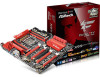
Motherboard Layout 12 Fatal1ty X99 Professional Series 3 4 5 FATAL TY CMOS Battery USB3_8 CHA_FAN3 19 20 21 22 S_SATA3_0_1 M2_1 S_SATA3_2_3 CT5 CT4 RoHS CT3 CT2 CT1 23 MINI_PCIE1 Purity SoundTM 2 CT5 HD_AUDIO1 1 T BT1 1 SATA3_0_1 PCIE2 PCIE3 X99 Professional PCIE4 Intel X99 - ASRock Fatal1ty X99 Professional | Quick Installation Guide - Page 6
No. Description 1 2 x 284-pin DDR4 DIMM Slots (DDR4_A1, DDR4_B1) 2 2 x 284-pin DDR4 DIMM Slots (DDR4_A2, DDR4_B2) 3 8 pin ATX 12V Power Connector (ATX12V1) 4 4 pin ATX 12V Power Connector (ATX12V2) 5 CPU Fan Connector (CPU_FAN1) 6 2 x 284-pin DDR4 DIMM Slots (DDR4_D2, DDR4_C2) 7 2 x 284-pin DDR4 - ASRock Fatal1ty X99 Professional | Quick Installation Guide - Page 7
COM Port Header (COM1) 42 PCIe Power Connector (PCIE_PWR1) 43 Thunderbolt AIC Connector (TB1) 44 Front Panel Audio Header (HD_AUDIO1) 45 Power Fan Connector (PWR_FAN1) Fatal1ty X99 Professional Series English 3 - ASRock Fatal1ty X99 Professional | Quick Installation Guide - Page 8
1.4 I/O Panel 1 2 46 3 57 15 14 13 12 11 10 98 No. Description No. Description 1 Fatal1ty Mouse Port (USB1) 10 USB 3.0 Ports (USB3_56) 2 USB 2.0 Port (USB2) 11 USB 3.0 Ports (USB3_34) 3 LAN RJ-45 Port (ASMedia ASM1074 hub) (Qualcomm® Atheros® KillerTM E2200 - ASRock Fatal1ty X99 Professional | Quick Installation Guide - Page 9
Fatal1ty X99 Professional Series * There are two LEDs on each LAN port. Please refer to the table below for the LAN port LED indications. ACT/LINK LED SPEED - ASRock Fatal1ty X99 Professional | Quick Installation Guide - Page 10
CPU support list on ASRock's website as well. ASRock website http://www.asrock.com. 1.1 Package Contents • ASRock Fatal1ty X99 Professional Series Motherboard (EATX Form Factor) • ASRock Fatal1ty X99 Professional Series Quick Installation Guide • ASRock Fatal1ty X99 Professional Series Support CD - ASRock Fatal1ty X99 Professional | Quick Installation Guide - Page 11
Fatal1ty X99 Professional Series 1.2 Specifications Platform CPU • EATX Form Factor • 8 Layer PCB • 4 x 2oz copper • High Density Glass Fabric PCB • Supports Intel® CoreTM i7 and Xeon® 18-Core Processors Family for the LGA 2011-3 Socket • Digi Power design • 12 Power Phase design (Supports up to - ASRock Fatal1ty X99 Professional | Quick Installation Guide - Page 12
Rear Panel • 1 x PS/2 Mouse/Keyboard Port I/O • 1 x Optical SPDIF Out Port • 1 x Fatal1ty Mouse Port (USB 2.0) (Supports ESD Protection (ASRock Full Spike Protection)) • 1 x USB 2.0 Port (Supports ESD Protection (ASRock Full Spike Protection)) • 4 x USB 3.0 Ports (ASMedia ASM1074 hub - ASRock Fatal1ty X99 Professional | Quick Installation Guide - Page 13
Fatal1ty X99 Professional Series • 2 x USB 3.0 Ports (Supports ESD Protection (ASRock Full Spike Protection)) • 2 x RJ-45 LAN Ports with LED (ACT/LINK LED and SPEED LED) • 1 x Clear CMOS Switch • HD Audio Jacks: Rear Speaker / Central / Bass / - ASRock Fatal1ty X99 Professional | Quick Installation Guide - Page 14
BIOS Feature Hardware Monitor OS Certifications • 1 x Vertical Type A USB 3.0 • 2 x USB 3.0 Headers (Support 4 USB 3.0 ports) (ASMedia ASM1074 hub) (Supports ESD Protection (ASRock Full Spike Protection)) • 1 x Dr. Debug with LED • 1 x Power Switch with LED • 1 x Reset Switch with LED • V-ProbeTM: - ASRock Fatal1ty X99 Professional | Quick Installation Guide - Page 15
Fatal1ty X99 Professional Series * For detailed product information, please visit our website: http://www.asrock.com Please realize that there is a certain risk involved with overclocking, including adjusting the setting in the BIOS, applying Untied Overclocking Technology, or using third- - ASRock Fatal1ty X99 Professional | Quick Installation Guide - Page 16
Pre-installation Precautions Take note of the following precautions before you install motherboard components or change any motherboard settings. • Make sure to unplug the power cord before installing or removing the motherboard components. Failure to do so may cause physical injuries and damages to - ASRock Fatal1ty X99 Professional | Quick Installation Guide - Page 17
Fatal1ty X99 Professional Series 2.1 Installing the CPU 1. Before you insert the will be seriously damaged. 2. Unplug all power cables before installing the CPU. CAUTION: Please note that X99 platform is only compatible with the LGA 2011-3 socket, which is incompatible with the LGA 2011 socket ( - ASRock Fatal1ty X99 Professional | Quick Installation Guide - Page 18
A 3 B 4 5 14 English - ASRock Fatal1ty X99 Professional | Quick Installation Guide - Page 19
Fatal1ty X99 Professional Series 6 A B 7 A B 8 Please save and replace the cover if the processor is removed. The cover must be placed if you wish to return the motherboard for after service. 15 English - ASRock Fatal1ty X99 Professional | Quick Installation Guide - Page 20
2.2 Installing the CPU Fan and Heatsink 1 16 2 CPU_FAN English - ASRock Fatal1ty X99 Professional | Quick Installation Guide - Page 21
Fatal1ty X99 Professional Series 2.3 Installation of Memory Modules (DIMM) This motherboard provides eight 284-pin DDR4 (Double Data Rate 4) DIMM slots, and supports Quad Channel Memory Technology. 1. For quad channel configuration, you always need to install identical (the same brand, speed, size - ASRock Fatal1ty X99 Professional | Quick Installation Guide - Page 22
1 2 3 18 English - ASRock Fatal1ty X99 Professional | Quick Installation Guide - Page 23
Fatal1ty X99 Professional Series 2.4 Expansion Slots (PCI Express Slots) There are 5 PCI Express slots and 1 mini-PCI Express slot on the motherboard. Before installing an expansion card, please make sure that the power supply is switched off or the power cord is unplugged. Please read the - ASRock Fatal1ty X99 Professional | Quick Installation Guide - Page 24
Way SLITM Mode x8 N/A x8 N/A *4-Way CrossFireXTM and 4-Way SLITM are not supported for CPU with 28 PCIe lanes. For a better thermal environment, please connect a chassis fan to the motherboard's chassis fan connector (CHA_FAN1, CHA_FAN2 or CHA_FAN3) when using multiple graphics cards. English - ASRock Fatal1ty X99 Professional | Quick Installation Guide - Page 25
Fatal1ty X99 Professional Series 2.5 Jumpers Setup The illustration shows how jumpers are setup. When the jumper cap is placed on the pins, the jumper is "Short". If no - ASRock Fatal1ty X99 Professional | Quick Installation Guide - Page 26
place jumper caps over these headers and connectors. Placing jumper caps over the headers and connectors will cause permanent damage to the motherboard. System Panel Header (9-pin PANEL1) (see p.1, No. 32) PLED+ PLEDPWRBTN# GND 1 GND RESET# GND HDLEDHDLED+ Connect the power switch, reset switch - ASRock Fatal1ty X99 Professional | Quick Installation Guide - Page 27
Fatal1ty X99 Professional Series Serial ATA3 Connectors (S_SATA3_0_1: see p.1, No. 22) (S_SATA3_2_3: see PUSB_PWR Besides two USB 2.0 ports on the I/O panel, there are two headers on this motherboard. Each USB 2.0 header can support two ports. USB 3.0 Headers (19-pin USB3_7_8) (see p.1, No. 18) ( - ASRock Fatal1ty X99 Professional | Quick Installation Guide - Page 28
for connecting audio devices to the front audio panel. 1. High Definition Audio supports Jack Sensing, but the panel wire on the chassis must support HDA to function correctly. Please follow the instructions in our manual and chassis manual to install your system. 2. If you use an AC'97 audio panel - ASRock Fatal1ty X99 Professional | Quick Installation Guide - Page 29
Fatal1ty X99 Professional Series CPU Fan Connectors (4-pin CPU_FAN1) (see p.1, No. 5) (3-pin CPU_FAN2) (see p.1, No. 8) +12V CPU_FAN_SPEED GND FAN_SPEED_CONTROL GND FAN_VOLTAGE CPU_FAN_SPEED This motherboard provides a 4-Pin CPU fan (Quiet Fan) connector. If you plan to connect a 3-Pin CPU - ASRock Fatal1ty X99 Professional | Quick Installation Guide - Page 30
connector via the GPIO cable. *Please install the Thunderbolt™ AIC card to PCIE3 (default slot). This COM1 header supports a serial port module. This connector supports Trusted Platform Module (TPM) system, which can securely store keys, digital certificates, passwords, and data. A TPM system also - ASRock Fatal1ty X99 Professional | Quick Installation Guide - Page 31
V-ProbeTM (7-pin VOL_ CON1) (see p.1, No. 15) Fatal1ty X99 Professional Series 1 I.5V PCH 1.05V PCH 1.05V CPU VCCM CORE3 VCC_IN GND Users are able to measure onboard components voltage. PIN1: 1.5V PCH: PCH PLL Voltage - ASRock Fatal1ty X99 Professional | Quick Installation Guide - Page 32
2.7 Smart Switches The motherboard has eleven smart switches: Power Switch, Reset Switch, Clear CMOS Switch, Rapid OC Buttons, Menu Button, PCIe ON/OFF Switch, Slow Mode Switch, BIOS Selection - ASRock Fatal1ty X99 Professional | Quick Installation Guide - Page 33
Fatal1ty X99 Professional Series PCIe ON/OFF If you do not want to use your PCIE card, please remove it from the motherboard. Slow Mode Switch (SLOWMODE) (see p.1, No. 14) OFF ON If Slow not able to update the backup BIOS manually. Users may refer to the BIOS LEDs (BIOS_A_LED or BIOS_B_LED) - ASRock Fatal1ty X99 Professional | Quick Installation Guide - Page 34
ON OFF English LN2 Mode Switch (LN2MODE) (see p.1, No. 13) Direct Key Button (DIRKEY1) (see p.1, No. 30) The LN2 mode aids in eliminating the cold-boot bug issues in processors during extreme overclocking with Liquid Nitrogen. Direct Key Button allows users to turn on the system and directly enter - ASRock Fatal1ty X99 Professional | Quick Installation Guide - Page 35
Fatal1ty X99 Professional Series 2.8 Dr. Debug Dr. Debug is used to provide code information, which makes troubleshooting even easier. could not be detected. Please re-install the memory and CPU. If the problem still exists, please install only one memory module or try using other memory - ASRock Fatal1ty X99 Professional | Quick Installation Guide - Page 36
or try using other memory modules. d6 The VGA could not be recognized. Please clear CMOS and try re-installing the VGA card. If the problem still exists, please try installing the VGA card in other slots or use other VGA cards. d7 The Keyboard and mouse could not be recognized - ASRock Fatal1ty X99 Professional | Quick Installation Guide - Page 37
Fatal1ty X99 Professional Series 2.9 Post Status Checker Post Status Checker (PSC) diagnoses the computer when users power on the machine. It emits a red light to indicate whether the - ASRock Fatal1ty X99 Professional | Quick Installation Guide - Page 38
2.10 M.2_SSD (NGFF) Module Installation Guide The M.2 (M2_1), also known as the Next Generation Form Factor (NGFF), is a small size and versatile card edge connector that aims to replace mPCIe and - ASRock Fatal1ty X99 Professional | Quick Installation Guide - Page 39
C B A E D C B A E D NUT2 NUT1 Fatal1ty X99 Professional Series Step 3 Move the standoff based on the module type and length nut to be used. Hand tighten the standoff into the desired nut location on the motherboard. Step 5 Align and gently insert the M.2 (NGFF) SSD module into the M.2 - ASRock Fatal1ty X99 Professional | Quick Installation Guide - Page 40
M.2_SSD (NGFF) Module Support List PCIe Interface SATA Interface Plextor PX-G512M6e Plextor PX-G256M6e SanDisk SD6PP4M-128G SanDisk SD6PP4M-256G Samsung XP941-512G (MZHPU512HCGL) ADATA AXNS381E-128GM-B ADATA - ASRock Fatal1ty X99 Professional | Quick Installation Guide - Page 41
Fatal1ty X99 Professional Series 2.11 HDD Saver Cable Installation Guide The HDD Saver Connector on this motherboard allows you to (s). * The HDD Saver Connector supports up to two SATA HDDs. 2. Connect one end of the SATA data cable to a SATA port on the motherboard. Then connect the other end - ASRock Fatal1ty X99 Professional | Quick Installation Guide - Page 42
und Prozessoren auf der ASRock-Webseite: ASRock-Website http://www.asrock.com. 1.1 Lieferumfang • ASRock Fatal1ty X99 Professional Series - Motherboard (EATX-Formfaktor) • ASRock Fatal1ty X99 Professional Series - Schnellinstallationsanleitung • ASRock Fatal1ty X99 Professional Series - Support-CD - ASRock Fatal1ty X99 Professional | Quick Installation Guide - Page 43
Fatal1ty X99 Professional Series 1.2 Technische Daten Plattform • EATX-Formfaktor • 8-Layer-PCB • 4 x 2-oz-Kupfer • Leiterplatte mit hochdichtem Glasgewebe Prozessor • Unterstützt Intel® Core™ i7- und Xeon®-18-KernProzessorenfamilie für LGA 2011-3-Socket • Digipower-Design • 12- - ASRock Fatal1ty X99 Professional | Quick Installation Guide - Page 44
) • Erstklassige Blu-ray-Audiounterstützung • Unterstützt Überspannungsschutz (ASRock Full Spike Protection) • Unterstützt Purity Sound™ 2 - Nichicon Optischer SPDIF-Ausgang • 1 x Fatal1ty-Mausport (USB 2.0) (unterstützt Schutz gegen elektrostatische Entladung (ASRock Full Spike Protection)) • 1 x - ASRock Fatal1ty X99 Professional | Quick Installation Guide - Page 45
Fatal1ty X99 Professional Series • 4 x USB 3.0-Ports (ASMedia ASM1074-Hub) (unterstützt Schutz gegen elektrostatische Entladung (ASRock Full Spike Protection)) • 2 x USB 3.0-Ports (unterstützt Schutz gegen elektrostatische Entladung (ASRock Full Spike Protection)) • 2 x RJ-45-LAN-Port mit LED ( - ASRock Fatal1ty X99 Professional | Quick Installation Guide - Page 46
• 2 x USB 3.0-Stiftleisten (unterstützen 4 USB 3.0-Ports) (ASMedia ASM1074-Hub) (unterstützt Schutz gegen elektrostatische Entladung (ASRock Full Spike Protection)) • 1 x Dr. Debug mit LED • 1 x Ein-/Austaste mit LED • 1 x Reset-Taste mit LED • V-ProbeTM: 7-teilige Spannungsmesspunkte auf Platine • - ASRock Fatal1ty X99 Professional | Quick Installation Guide - Page 47
Fatal1ty X99 Professional Series * Detaillierte Produktinformationen finden Sie auf unserer Webseite: http://www.asrock.com Bitte beachten Sie, dass mit einer Übertaktung, zu der die Anpassung von BIOS-Einstellungen, die Anwendung der Untied Overclocking Technology oder die Nutzung von Ü - ASRock Fatal1ty X99 Professional | Quick Installation Guide - Page 48
1.3 Jumpereinstellung Die Abbildung zeigt, wie die Jumper eingestellt werden. Wenn die JumperKappe auf den Kontakten angebracht ist, ist der Jumper „kurzgeschlossen". Wenn keine Jumper-Kappe auf den Kontakten angebracht ist, ist der Jumper „offen". Die Abbildung zeigt einen 3-poligen Jumper, dessen - ASRock Fatal1ty X99 Professional | Quick Installation Guide - Page 49
Fatal1ty X99 Professional Series 1.4 Integrierte Stiftleisten und Anschlüsse Integrierte Stiftleisten und Anschlüsse sind KEINE Jumper. Bringen Sie KEINE JumperKappen an diesen Stiftleisten und Anschlüssen an. - ASRock Fatal1ty X99 Professional | Quick Installation Guide - Page 50
unterstützt. USB_PWR PP+ GND DUMMY 1 GND P+ PUSB_PWR Neben zwei USB 2.0-Ports an der E/A-Blende befinden sich zwei Stiftleisten an diesem Motherboard.Jede USB 2.0-Stiftleiste kann zwei Ports unterstützen. USB 3.0-Stiftleisten (19-polig, USB3_7_8) (siehe S. 1, Nr. 18) (19-polig, USB3_9_10) (siehe - ASRock Fatal1ty X99 Professional | Quick Installation Guide - Page 51
Fatal1ty X99 Professional Series Audiostiftleiste (Frontblende) (9-polig, HD_AUDIO1) (siehe S. 1, Nr. 44) GND PRESENCE# MIC_RET OUT_RET 1 OUT2_L J_SENSE OUT2_R MIC2_R MIC2_L Diese Stiftleiste dient dem Anschließen von Audiogerä - ASRock Fatal1ty X99 Professional | Quick Installation Guide - Page 52
ATX-Netzanschluss. Bitte schließen Sie es zur Nutzung eines 20-poligen ATX-Netzteils entlang Kontakt 1 und Kontakt 13 an. Dieses Motherboard bietet einen 8-poligen ATX-12-V-Netzanschluss und einen 4-poligen ATX12-V-Netzanschluss. Bitte schließen Sie zur Nutzung eines 4-poligen ATXNetzteils dieses - ASRock Fatal1ty X99 Professional | Quick Installation Guide - Page 53
Fatal1ty X99 Professional Series HDD-Saver-Anschluss (4-polig, SATA_PWR_1) 1 (siehe S. 1, Nr. 27) ThunderboltErweiterungskartenanschluss (5-polig, TBT1) (siehe S. 1, Nr. 43) Serieller-Port-Stiftleiste (9-polig, COM1) (siehe S. 1, Nr. 41) RRXD1 DDTR#1 - ASRock Fatal1ty X99 Professional | Quick Installation Guide - Page 54
V-ProbeTM (VOL_CON1 (7-polig) (siehe S. 1, Nr. 15) 1 I.5V PCH Benutzer können Span- 1.05V PCH nung integrierter Kompo- 1.05V CPU VCCM CORE3 nenten messen. Kontakt 1: VCC_IN GND 1,5-V-PCH: PCH-PLL-Spannung Kontakt 2: 1,05-V-PCH: PCH-Spannung Kontakt 3: 1,05-V-CPU: CPU-I/O-Spannung ( - ASRock Fatal1ty X99 Professional | Quick Installation Guide - Page 55
Fatal1ty X99 Professional Series 1.5 Intelligente Schalter Das Motherboard verfügt über elf spezielle Tasten: Ein/Aus, Reset, CMOS löschen, Rapid OC-Tasten, Menü, PCIe-Ein/Aus, Reduzierte Geschwindigkeit, BIOSAuswahl, LN2-Modus, Direkttaste. Ein-/ - ASRock Fatal1ty X99 Professional | Quick Installation Guide - Page 56
BIOS-Auswahlschalter (BIOS_SEL1) (siehe S. 1, Nr. 28) AB Der BIOS-Auswahlschalter ermöglicht dem System, von BIOS A oder BIOS B zu starten. Dieses Motherboard verfügt über zwei BIOS-Chips, ein primäres BIOS (BIOS_A) und ein Ausfall-BIOS (BIOS_B), die Sicherheit und Stabilität Ihres Systems - ASRock Fatal1ty X99 Professional | Quick Installation Guide - Page 57
LN2-Modusschalter (LN2MODE) (siehe S. 1, Nr. 13) Direkttaste (DIRKEY1) (siehe S. 1, Nr. 30) Fatal1ty X99 Professional Series Der LN2-Modus hilft ON bei der Eliminierung OFF von Kaltstartfehlern in Prozessoren bei extremer Übertaktung mit flüssigem Stickstoff. Direkttaste ermöglicht Nutzern - ASRock Fatal1ty X99 Professional | Quick Installation Guide - Page 58
site Internet de ASRock. Site Internet ASRock http://www.asrock.com. 1.1 Contenu de l'emballage • Carte mère ASRock Fatal1ty X99 Professional Series (facteur de forme EATX) • Guide d'installation rapide ASRock Fatal1ty X99 Professional Series • CD d'assistance ASRock Fatal1ty X99 Professional Series - ASRock Fatal1ty X99 Professional | Quick Installation Guide - Page 59
Fatal1ty X99 Professional Series 1.2 Spécifications Plateforme • Facteur de forme EATX • PCB 8 couches • 4 x cuivre 2 onces • PCB en tissu de verre haute densité Processeur Chipset • Prends en charge les familles de processeurs Intel® Core i7 et Xeon® pour le socket LGA 2011-3 • Conception Digi - ASRock Fatal1ty X99 Professional | Quick Installation Guide - Page 60
ère • 1 x port souris/clavier PS/2 • 1 x port sortie optique SPDIF • 1 x ports souris Fatal1ty (USB 2.0) (Protection contre les décharges électrostatiques (Protection complète contre les pics ASRock)) • 1 x port USB 2.0 (Protection contre les décharges électrostatiques (Protection complète contre - ASRock Fatal1ty X99 Professional | Quick Installation Guide - Page 61
Fatal1ty X99 Professional Series • 2 x ports USB 3.0 (Protection contre les décharges électrostatiques (Protection complète contre les pics ASRock)) • 2 x ports RJ-45 LAN avec LED (LED ACT/LIEN et LED VITESSE) • 1 x bouton Clear CMOS • Connecteurs jack audio HD : Haut-parleur arrière / central / - ASRock Fatal1ty X99 Professional | Quick Installation Guide - Page 62
• 1 x Dr Debug avec témoin LED • 1 x bouton de mise en marche avec témoin LED • 1 x bouton de réinitialisation avec témoin LED • V-ProbeTM: 7 sets de points de mesure de tension • embarqués • Boutons pour OC rapide : Boutons +/- pour régler la- fréquence OC • 1 x menu bouton • 1 x interrupteur - ASRock Fatal1ty X99 Professional | Quick Installation Guide - Page 63
Fatal1ty X99 Professional Series * pour des informations détaillées de nos produits, veuillez visiter notre site : http://www.asrock.com Il est important de signaler que l'overcloking présente certains risques, incluant des modifications du BIOS, l'application d'une technologie d'overclocking déliée - ASRock Fatal1ty X99 Professional | Quick Installation Guide - Page 64
1.3 Configuration des cavaliers (jumpers) L'illustration ci-dessous vous renseigne sur la configuration des cavaliers (jumpers). Lorsque le capuchon du cavalier est installé sur les broches, le cavalier est « courtcircuité ». Si le capuchon du cavalier n'est pas installé sur les broches, le cavalier - ASRock Fatal1ty X99 Professional | Quick Installation Guide - Page 65
Fatal1ty X99 Professional Series 1.4 Embases et connecteurs de la carte mère Les embases et connecteurs situés sur la carte NE SONT PAS des cavaliers. Ne placez JAMAIS de - ASRock Fatal1ty X99 Professional | Quick Installation Guide - Page 66
No. 38) USB_PWR PP+ GND DUMMY 1 GND P+ PUSB_PWR Neben zwei USB 2.0-Ports an der E/A-Blende befinden sich zwei Stiftleisten an diesem Motherboard. Jede USB 2.0-Stiftleiste kann zwei Ports unterstützen. Français Embases USB 3.0 (USB3_7_8 à 19 broches) (voir p.1, No. 18) (USB3_9_10 à 19 broches - ASRock Fatal1ty X99 Professional | Quick Installation Guide - Page 67
Fatal1ty X99 Professional Series Embase audio du panneau frontal (HD_AUDIO1 à 9 broches) (voir p.1, é du châssis doit être compatible avec la HDA pour fonctionner correctement. Veuillez suivre les instructions figurant dans notre manuel et dans le manuel du châssis pour installer votre système. - ASRock Fatal1ty X99 Professional | Quick Installation Guide - Page 68
Connecteurs du ventilateur du processeur (CPU_FAN1 à 4 broches) (voir p.1, No. 5) (CPU_FAN2 à 3 broches) (voir p.1, No. 8) +12V CPU_FAN_SPEED GND FAN_SPEED_CONTROL GND FAN_VOLTAGE CPU_FAN_SPEED Cette carte mère est dotée d'un connecteur pour ventilateur de processeur (Quiet Fan) à 4 broches. - ASRock Fatal1ty X99 Professional | Quick Installation Guide - Page 69
Fatal1ty X99 Professional Series Connecteur sauvegarde HDD 1 (SATA_PWR_1 à 4 broches) (voir p.1, No. 22) Connecteur Thunderbolt AIC (TBT1 à 5 broches) (voir p.1, No. 31) Embase pour port série (COM1 à 9 broches) (voir p.1, No. - ASRock Fatal1ty X99 Professional | Quick Installation Guide - Page 70
V-ProbeTM (VOL_CON1 7 broches) (voir p.1, No. 15) 1 I.5V PCH Les utilisateurs peuvent mesurer la tension des 1.05V PCH composants embarqués. 1.05V CPU VCCM BROCHE1 : CORE3 VCC_IN GND 1,5 V PCH : Tension PCH PLL BROCHE2 : 1,05 V PCH : Tension PCH BROCHE3 : 1,05 V CPU : Tension E/S CPU ( - ASRock Fatal1ty X99 Professional | Quick Installation Guide - Page 71
Fatal1ty X99 Professional Series 1.5 Boutons intelligents La carte mère est équipée de onze boutons intelligents : Bouton d'alimentation, bouton de réinitialisation, bouton effacer CMOS, boutons OC rapide, bouton menu, - ASRock Fatal1ty X99 Professional | Quick Installation Guide - Page 72
ON 1234 Interrupteur marche/ L'interrupteur marche/arrêt arrêt PCIe PCIe permet à l'utilisateur (PCIE_SWITCH) d'activer et de désactiver les (voir p.1, No. 12) 1: PCIE1 2: PCIE2 3: PCIE4 4: PCIE5 fentes PCIE x16 correspondantes. Si l'une des 16 cartes PCIE installées est défectueuse, vous - ASRock Fatal1ty X99 Professional | Quick Installation Guide - Page 73
Interrupteur mode LN2 (LN2MODE) (voir p.1, No. 13) Bouton Direct Key (DIRKEY1) (voir p.1, No. 30) Fatal1ty X99 Professional Series Le mode LN2 aide à éliminer ON le bogue associé au démarrage OFF à froid des processeurs en cas d'overclocking extrême au nitrogène liquide. - ASRock Fatal1ty X99 Professional | Quick Installation Guide - Page 74
Web di ASRock. Sito Web di ASRock http://www.asrock.com. 1.1 Contenuto della confezione • Scheda madre ASRock Fatal1ty X99 Professional Series (Form Factor EATX) • Guida all'installazione rapida di ASRock Fatal1ty X99 Professional Series • CD di supporto di ASRock Fatal1ty X99 Professional Series - ASRock Fatal1ty X99 Professional | Quick Installation Guide - Page 75
Fatal1ty X99 Professional Series 1.2 Specifiche Piattaforma CPU Chipset • Fattore di forma EATX • PCB a 8 layer • 4 x 2oz rame • PBC di fibra di vetro ad alta densità • Supporta la famiglia di processori Intel® CoreTM i7 e Xeon® 18-Core per il socket LGA 2011-3 • Design Digi Power • Potenza a 12 - ASRock Fatal1ty X99 Professional | Quick Installation Guide - Page 76
posteriore • 1 x porta mouse/tastiera PS/2 • 1 x porta uscita SPDIF ottico • 1 x Porta mouse Fatal1ty (USB 2.0) (supporto protezione da scariche elettrostatiche (ESD) (protezione completa ASRock dai picchi di corrente)) • 1 x Porta USB 2.0 (supporto protezione da scariche elettrostatiche (ESD - ASRock Fatal1ty X99 Professional | Quick Installation Guide - Page 77
Fatal1ty X99 Professional Series • 4 x Porte USB 3.0 (hub ASMedia ASM1074) (supporto protezione da scariche elettrostatiche (ESD) (protezione completa ASRock dai picchi di corrente)) • 2 x Porte USB 3.0 (supporto protezione da scariche elettrostatiche (ESD) (protezione completa ASRock dai picchi di - ASRock Fatal1ty X99 Professional | Quick Installation Guide - Page 78
A • 2 x Collettori USB 3.0 (supporto di 4 porte 4 USB 3.0) (supporto protezione da scariche elettrostatiche (ESD) (ASMedia ASM1074-Hub) (protezione completa ASRock dai picchi di corrente)) • 1 x Dr. Debug con LED • 1 x interruttore d'alimentazione con LED • 1 x interruttore di ripristino con LED - ASRock Fatal1ty X99 Professional | Quick Installation Guide - Page 79
Fatal1ty X99 Professional Series Certificazioni • FCC, CE, WHQL • ErP/EuP Ready (è necessaria alimentazione ErP/EuP ready) * Per informazioni dettagliate sul prodotto, visitare il nostro sito Web: http://www.asrock.com Prestare attenzione al potenziale rischio previsto nella pratica di - ASRock Fatal1ty X99 Professional | Quick Installation Guide - Page 80
1.3 Impostazione jumper L'illustrazione mostra in che modo vengono impostati i jumper. Quando il cappuccio del jumper è posizionato sui pin, il jumper è "cortocircuitato". Se sui pin non è posizionato alcun cappuccio del jumper, il jumper è "aperto". L'illustrazione mostra un jumper a 3 pin i cui - ASRock Fatal1ty X99 Professional | Quick Installation Guide - Page 81
Fatal1ty X99 Professional Series 1.4 Header e connettori sulla scheda Gli header e i connettori sulla scheda NON sono jumper. NON posizionare cappucci del jumper su questi header e connettori. Il posizionamento di - ASRock Fatal1ty X99 Professional | Quick Installation Guide - Page 82
Header LED di alimentazione (PLED1 a 3 pin) (vedere pag. 1, n. 29) Connettori Serial ATA3 (S_SATA3_0_1 vedere pag. 1, n. 22) (S_SATA3_2_3: vedere pag.1, n. 23) (SATA3_0_1: vedere pag. 1, n. 24) (SATA3_2_3: vedere pag.1, n. 25) (SATA3_4_5: vedere pag. 1, n. 26) SATA3_0 S_SATA3_2 S_SATA3_0 1 PLED- - ASRock Fatal1ty X99 Professional | Quick Installation Guide - Page 83
Fatal1ty X99 Professional Series Header audio pannello anteriore (AUDIO1_HD a 9 pin) (vedere pag. 1, n. 44) GND deve supportare HDA per funzionare correttamente. Seguire le istruzioni presenti nel nostro manuale e nel manuale dello chassis per installare il sistema. 2. Se si utilizza un pannello - ASRock Fatal1ty X99 Professional | Quick Installation Guide - Page 84
Connettori della ventola della CPU (CPU_FAN1 a 4 pin) (vedere pag. 1, n. 5) (CPU_FAN2 a 3 pin) (vedere pag. 1, n. 8) +12V CPU_FAN_SPEED GND FAN_SPEED_CONTROL GND FAN_VOLTAGE CPU_FAN_SPEED Questa scheda madre è dotata di un connettore per la ventola della CPU (Ventola silenziosa) a 4 pin. Se si - ASRock Fatal1ty X99 Professional | Quick Installation Guide - Page 85
Fatal1ty X99 Professional Series ConnettoreThunderbolt AIC (TBT1 5-pin) (vedere pag. 1, n. 43) Header porta seriale (COM1 a 9 pin) (vedere pag. 1, n. 41) Header TPM (TPMS1 a 17 pin) (vedere pag. 1, n. 36) RRXD1 - ASRock Fatal1ty X99 Professional | Quick Installation Guide - Page 86
V-ProbeTM (7-pin VOL_ CON1) (vedere pag. 1, n. 15) 1 Gli utenti sono in grado di I.5V PCH 1.05V PCH misurare la tensione dei 1.05V CPU componenti integrati. VCCM CORE3 PIN1: VCC_IN 1,5V PCH: GND Tensione PCH PLL PIN2: 1,05V PCH: Tensione PCH PIN3: 1,05V CPU: Tensione I/O CPU (CPU_ - ASRock Fatal1ty X99 Professional | Quick Installation Guide - Page 87
Fatal1ty X99 Professional Series 1.5 Interruttori intuitivi La scheda madre è dotata di dieci interruttori intuitivi: Interruttore di alimentazione, Interruttore di ripristino, Interruttore Clear CMOS, Pulsanti OC rapido, Pulsante menu, - ASRock Fatal1ty X99 Professional | Quick Installation Guide - Page 88
ON OFF Italiano Interruttore ON/OFF PCIe (PCIE_SWITCH) (vedere pag. 1, n. 12) ON 1234 1: PCIE1 2: PCIE2 3: PCIE4 4: PCIE5 L'interruttore ON/OFF PCIe consente di abilitare e disabilitare i 16 alloggi PCIE corrispondenti. Quando una delle 16 schede PCIE installate è guasta, è possibile usare l' - ASRock Fatal1ty X99 Professional | Quick Installation Guide - Page 89
Interruttore modalità LN2 (LN2MODE) (vedere pag. 1, n. 13) Tasto Direct Key (DIRKEY1) (vedere pag. 1, n. 30) Fatal1ty X99 Professional Series ON La modalità LN2 aiuta ad eliminare i problemi di bug OFF dovuti all'accensione a freddo nei processori, durante l'overclock estremo ad azoto - ASRock Fatal1ty X99 Professional | Quick Installation Guide - Page 90
. Sitio web de ASRock http://www. asrock.com. 1.1 Contenido del paquete • Placa base ASRock Fatal1ty X99 Professional Series (Factor de forma EATX) • Guía de instalación rápida de ASRock Fatal1ty X99 Professional Series • CD de soporte de ASRock Fatal1ty X99 Professional Series • 1 escudo panel - ASRock Fatal1ty X99 Professional | Quick Installation Guide - Page 91
Fatal1ty X99 Professional Series 1.2 Especificaciones Plataforma CPU Conjunto de chips • Factor de forma EATX • Circuito impreso (PCB) de 8 capas • 4 unidades de 2oz de cobre • PCB de fibra de vidrio de alta densidad • Admite la familia de procesadores Intel® CoreTM i7 y Xeon® 18-Core para el zó - ASRock Fatal1ty X99 Professional | Quick Installation Guide - Page 92
Panel trasero I/O • 1 puerto de ratón/teclado PS/2 • 1 puerto de salida SPDIF óptica • 1 puerto de ratón Fatal1ty (USB 2.0) (compatible con protección contra electricidad estática (protección ASRock Full Spike)) • 1 puerto USB 2.0 (compatible con protección contra electricidad estática (protecci - ASRock Fatal1ty X99 Professional | Quick Installation Guide - Page 93
Fatal1ty X99 Professional Series • 2 puertos USB 3.0 (compatible con protección contra electricidad estática (protección ASRock Full Spike)) • 2 puerto LAN RJ-45 con LED (LED ACT/ENLACE y LED VELOCIDAD) • 1 interruptor de borrado CMOS • Conector de audio HD: Altavoz trasero / Central / Graves / - ASRock Fatal1ty X99 Professional | Quick Installation Guide - Page 94
Función del BIOS Monitor del hardware SO Certificaciones • 1 x Dr. Debug con indicador LED • 1 interruptor de alimentación con indicador LED • 1 interruptor de reseteo con indicador LED • 1 V-ProbeTM: 7 conjuntos de puntos de medición de voltaje integrados • Botones Rapid OC: botones +/- para - ASRock Fatal1ty X99 Professional | Quick Installation Guide - Page 95
Fatal1ty X99 Professional Series * Para obtener más información acerca del producto, visite nuestro sitio web: http://www.asrock.com Tenga en cuenta que existen ciertos riesgos relacionados con el overclocking (sobreaceleración), incluyendo el ajuste de la configuración del BIOS, aplicando la - ASRock Fatal1ty X99 Professional | Quick Installation Guide - Page 96
1.3 Instalación de los puentes La instalación muestra cómo deben instalarse los puentes. Cuando la tapa de puente se coloca en los pines, el puente queda "Corto". Si no coloca la tapa de puente en los pines, el puente queda "Abierto". La ilustración muestra un puente de 3 pines cuyo pin 1 y pin 2 - ASRock Fatal1ty X99 Professional | Quick Installation Guide - Page 97
Fatal1ty X99 Professional Series 1.4 Conectores y cabezales incorporados Los cabezales y conectores incorporados NO son puentes. NO coloque tapas de puente sobre estos cabezales y conectores. Si coloca tapas de puente - ASRock Fatal1ty X99 Professional | Quick Installation Guide - Page 98
Cabezal de indicador LED de alimentación (PLED1 de 3 pines) (consulte la pág.1, N.º 29) 1 PLED- PLED+ PLED+ Conectores Serie ATA3 (S_SATA3_0_1 consulte la pág.1, N.º 22) (S_SATA3_2_3: (consulte la pág. 1, N.º 23) (SATA3_0_1: consulte la pág.1, N.º 24) (SATA3_2_3: (consulte la pág. 1, N.º 25) ( - ASRock Fatal1ty X99 Professional | Quick Installation Guide - Page 99
Fatal1ty X99 Professional Series Cabezal de audio del panel frontal (HD_AUDIO1 de 9 pines) ( compatible con HDA para que pueda funcionar correctamente. Siga las instrucciones que se indican en nuestro manual y en el manual del chasis para instalar su sistema. 2. Si utiliza un panel de audio AC'97, - ASRock Fatal1ty X99 Professional | Quick Installation Guide - Page 100
Conectores del ventilador de la CPU (CPU_FAN1 de 4 pines) (consulte la pág.1, N.º 5) +12V CPU_FAN_SPEED GND FAN_SPEED_CONTROL (CPU_FAN2 de 3 pines) (consulte la pág.1, N.º 8) GND FAN_VOLTAGE CPU_FAN_SPEED Esta placa base contiene un conector de ventilador (ventilador silencioso) de CPU de 4 - ASRock Fatal1ty X99 Professional | Quick Installation Guide - Page 101
Fatal1ty X99 Professional Series Conector de ahorro de energía HDD 1 (SATA_PWR_1 de 4 pines) (consulte la pág.1, N.º 27) Conector Thunderbolt AIC (TBT1 de 5 pines) (consulte la pág.1, N.º 43) Cabezal de puerto - ASRock Fatal1ty X99 Professional | Quick Installation Guide - Page 102
V-ProbeTM VOL_CON1 de 7 contactos) (consulte la pág.1, N.º 15) 1 I.5V PCH 1.05V PCH 1.05V CPU VCCM CORE3 VCC_IN GND Los usuarios pueden medir el voltaje de los componentes integrados. CONTACTO1: 1,5 V PCH: voltaje PLL PCH CONTACTO2: 1,05 V PCH: voltaje de PCH CONTACTO3: 1,05 V CPU: voltaje de E/S - ASRock Fatal1ty X99 Professional | Quick Installation Guide - Page 103
Fatal1ty X99 Professional Series 1.5 Interruptores inteligentes La placa base contiene undici interruptores inteligentes: Interruptor de alimentación, Interruptor de restablecimiento, Borrar CMOS, Botones Rapid OC, Botón Menú, Interruptor de - ASRock Fatal1ty X99 Professional | Quick Installation Guide - Page 104
Interruptor de activación desactivación de PCIe (consulte la pág.1, N.º 12) ON 1234 1: PCIE1 2: PCIE2 3: PCIE4 4: PCIE5 El interruptor de encendido/ apagado de PCIe le permite activar y desactivar las ranuras PCIE x16 correspondientes. Cuando una de las tarjetas PCIE x16 instaladas no funcione, - ASRock Fatal1ty X99 Professional | Quick Installation Guide - Page 105
Interruptor del Modo LN2 (LN2MODE) (consulte la pág.1, N.º 13) Botón de tecla directa (DIRKEY1) (consulte la pág.1, N.º 30) Fatal1ty X99 Professional Series El modo LN2 ayuda a ON eliminar los problemas de OFF errores del arranque en frío de los procesadores durante el overclocking extremo - ASRock Fatal1ty X99 Professional | Quick Installation Guide - Page 106
1 ASRock Fatal1ty X99 Professional Series ASRock ASRock BIOS ASRock ASRock VGA ASRock http://www.asrock.com. 1.1 ASRock Fatal1ty X99 Professional Series EATX ASRock Fatal1ty X99 Professional Series ASRock Fatal1ty X99 Professional Series • 1 ASRock SLI_Bridge - 2 ASRock - ASRock Fatal1ty X99 Professional | Quick Installation Guide - Page 107
Fatal1ty X99 Professional Series 1.2 EATX • 8 4 x 2 Intel® CoreTM i7 и 18 Xeon LGA 2011-3 • Digi Power design 12 1300 Intel® Turbo Boost 2.0 Untied Overclocking • Intel® X99 Память Quad Channel DDR4 Memory Technology • 8 DDR4 DIMM DDR4 3400+(OC)*/29 33+(OC)/2800( - ASRock Fatal1ty X99 Professional | Quick Installation Guide - Page 108
3az PXE • 1 x porta mouse/tastiera PS/2 • 1 x porta uscita SPDIF ottico • 1 x Fatal1ty (USB 2.0 ASRock Full Spike Protection) • 1 x Porta USB 2.0 (supporto protezione da scariche elettrostatiche (ESD) (protezione completa ASRock dai picchi di corrente)) • 4 x Porte USB 3.0 (hub ASMedia ASM1074 - ASRock Fatal1ty X99 Professional | Quick Installation Guide - Page 109
Fatal1ty X99 Professional Series • 2 x Porte USB 3.0 (supporto protezione da scariche elettrostatiche (ESD) (protezione completa ASRock dai picchi di corrente)) • 2 Porta RJ-45 LAN con LED (LED ACT/LINK e LED SPEED) • 1 x interruttore per azzerare la CMOS HD Audio • 10 x SATA3 6,0 ГБ/с - ASRock Fatal1ty X99 Professional | Quick Installation Guide - Page 110
ОС • 2 x Collettori USB 3.0 (supporto di 4 porte 4 USB 3.0) (ASMedia ASM1074-Hub) (supporto protezione da scariche elettrostatiche (ESD) (protezione completa ASRock dai picchi di corrente)) • 1 x Dr. Debug con LED • 1 x interruttore d'alimentazione con LED • 1 x interruttore di ripristino con LED - ASRock Fatal1ty X99 Professional | Quick Installation Guide - Page 111
Fatal1ty X99 Professional Series • FCC, CE, WHQL ErP/EuP ErP/EuP) http://www.asrock.com BIOS Untied Overclocking Technology 32 Windows 4 64 Windows Windows ASRock XFast RAM. 107 - ASRock Fatal1ty X99 Professional | Quick Installation Guide - Page 112
1.3 3 1 и 2 CMOS (CLRCMOS1 1, № 40) CMOS CLRCMOS1 CMOS 15 2 и 3 на CLRCMOS1 на 5 CMOS BIOS CMOS BIOS CMOS CMOS. CMOS CMOS. 108 - ASRock Fatal1ty X99 Professional | Quick Installation Guide - Page 113
Fatal1ty X99 Professional Series 1.4 9 PANEL1 1, № 32) PLED+ PLEDPWRBTN# GND 1 GND RESET# GND HDLEDHDLED+ PWRBTN RESET PLED S1/S3 S4 S5 HDLED 3 PLED1 1, № 29) 1 PLED- PLED+ PLED+ 109 - ASRock Fatal1ty X99 Professional | Quick Installation Guide - Page 114
Serial ATA3 (S_SATA3_0_1 1, № 22) (S_SATA3_2_3 1, № 23) (SATA3_0_1 1, № 24) (SATA3_2_3 1, № 25) (SATA3_4_5 1, № 26) SATA3_0 S_SATA3_2 S_SATA3_0 SATA3_1 S_SATA3_3 S_SATA3_1 SATA3 SATA 6,0 Гб/с. M.2 SATA M.2 Socket (M2_1 S_ SATA3_3 M.2 PCI Express M.2 Socket (M2_1 S_SATA3_3 - ASRock Fatal1ty X99 Professional | Quick Installation Guide - Page 115
Fatal1ty X99 Professional Series 9 HD_ AUDIO1 1, № 44) GND PRESENCE# MIC_RET OUT_RET 1 OUT2_L J_SENSE OUT2_R MIC2_R MIC2_L 1 HDA 2 AC'97 A Mic_IN (MIC) к MIC2_L. B Audio_R (RIN) к OUT2_R, Audio_L (LIN) к OUT2_L. C - ASRock Fatal1ty X99 Professional | Quick Installation Guide - Page 116
4 CPU_ FAN1 1, № 5) (3 CPU_ FAN2 1, № 8) +12V CPU_FAN_SPEED GND FAN_SPEED_CONTROL GND FAN_VOLTAGE CPU_FAN_SPEED 4 3 1-3. 24 ATXPWR1 1, № 17) 12 24 12 В (8 ATX12V1 1, № 3) (4 ATX12V2 1, № 4) 1 13 8 5 4 1 24 20 ATX 1 13. 8 12 В и 4 ATX 12 4 ATX 1 5. - ASRock Fatal1ty X99 Professional | Quick Installation Guide - Page 117
Fatal1ty X99 Professional Series Thunderbolt AIC (5 TBT1 1, № 43) 9 COM1 1, № 41) RRXD1 DDTR#1 DDSR#1 CCTS#1 1 RRI#1 RRTS#1 GND TTXD1 DDCD#1 AIC Thunderbolt 5 GPIO Thunderbolt PCIE3 COM1 17 TPMS1 1, № 36) 1 - ASRock Fatal1ty X99 Professional | Quick Installation Guide - Page 118
V-ProbeTM (7 VOL_CON1 1, № 15) 1 I.5V PCH 1.05V PCH 1.05V CPU VCCM CORE3 VCC_IN GND PIN1: 1,5 В PCH PCH PLL PIN2: 1,05 В PCH PCH PIN3: 1,05 CPU_V10) PIN4: VCCM DRAM PIN5: CORE3 3 8 PIN6: VCC_IN PIN7: GND 114 - ASRock Fatal1ty X99 Professional | Quick Installation Guide - Page 119
Fatal1ty X99 Professional Series 1.5 CMOS Rapid OC PCIe BIOS LN2 PWR 1, № 33) Power RST 1, № 34) Reset CMOS (CLRCBTN1 4, № 13) CMOS CMOS. Rapid OC: (MINUS 1, № 10) (PLUS 1, № 9) + Rapid OC - - ASRock Fatal1ty X99 Professional | Quick Installation Guide - Page 120
PCIe (PCIE_SWITCH 1, № 12) ON 1234 1: PCIE1 2: PCIE2 3: PCIE4 4: PCIE5 PCIe PCIE x16 PCIE x16 PCIe 1 2 PCIE PCIe 3 PCIe PCIE ON OFF SLOWMODE 1, № 14) BIOS (BIOS_SEL1 1, № 28) AB BIOS BIOS A или BIOS B. BIOS BIOS (BIOS_A) и BIOS BIOS_B BIOS BIOS - ASRock Fatal1ty X99 Professional | Quick Installation Guide - Page 121
LN2 (LN2MODE 1, № 13) DIRKEY1 1, № 30) Fatal1ty X99 Professional Series Режим LN2 ON OFF UEFI. 117 - ASRock Fatal1ty X99 Professional | Quick Installation Guide - Page 122
no site da ASRock. Site da ASRock http://www.asrock.com. 1.1 Conteúdo da embalagem • Placa Mãe ASRock Fatal1ty X99 Professional Series (Fator de Forma EATX) • Guia de Instalação Rápida da ASRock Fatal1ty X99 Professional Series • CD de Suporte da ASRock Fatal1ty X99 Professional Series • 1 x Painel - ASRock Fatal1ty X99 Professional | Quick Installation Guide - Page 123
Fatal1ty X99 Professional Series Português 1.2 Especificações Plataforma CPU Chipset • Formato EATX • PCB de 8 camadas • 4 x 2oz em cobre • Tecido de Vidro de Alta densidade PCB • Suporta Família de Processadores Intel® CoreTM i7 site da ASRock para obter mais informação. (http://www.asrock.com/) - ASRock Fatal1ty X99 Professional | Quick Installation Guide - Page 124
Technology (no Qualcomm® Atheros® KillerTM Série E2200) • Suporta Wake-On-LAN • Suporta Proteção contra Relâmpago/EDS (Proteção Total Contra Picos ASRock) • Suporta Energy Efficient Ethernet 802.3az • Suporta PXE E/S do painel posterior • 1 x Porta PS/2 para mouse/teclado • 1 x Porta de Saída - ASRock Fatal1ty X99 Professional | Quick Installation Guide - Page 125
Fatal1ty X99 Professional Series Português • 1 x Porta USB 2.0 (Suporta Proteção ESD (Proteção Total Contra Picos ASRock)) • 4 x Portas USB 3.0 (ASMedia ASM1074 núcleo)(Suporta Proteção ESD (Proteção Total Contra Picos ASRock)) • 2 x Portas USB 3.0 (Suporta Proteção ESD (Proteção Total Contra - ASRock Fatal1ty X99 Professional | Quick Installation Guide - Page 126
x USB 3.0 Tipo A Vertical • 2 x Plataformas USB 3.0 (Suporta 4 portas USB 3.0) (ASMedia ASM1074-Hub) (Suporta Proteção ESD (Proteção Total Contra Picos ASRock)) • 1 x Dr. Debug com LED • 1 x Interruptor de alimentação LED • 1 x Interruptor de reiniciar LED • V-ProbeTM: conjuntos de 7 pontos de medi - ASRock Fatal1ty X99 Professional | Quick Installation Guide - Page 127
Fatal1ty X99 Professional Series SO Certificações • Monitoramento da tensão: +12V, +5V, +3,3 V, Tensão obter informações detalhadas sobre o produto, por favor, visite o nosso site: http://www.asrock.com Por favor, observe que existe um certo risco envolvendo overclocking, incluindo o ajuste das - ASRock Fatal1ty X99 Professional | Quick Installation Guide - Page 128
1.3 Configuração dos jumpers A imagem abaixo mostra como os jumpers são configurados. Quando a tampa do jumper é colocada nos pinos, o jumper é "Curto". Se não for colocada uma tampa de jumper nos pinos, o jumper é "Aberto". A imagem mostra um jumper de 3 pinos cujos pino1 e pino2 estão "Curtos" - ASRock Fatal1ty X99 Professional | Quick Installation Guide - Page 129
Fatal1ty X99 Professional Series 1.4 Suportes e conectores onboard Os conectores e suportes onboard NÃO são jumpers. NÃO coloque tampas de jumpers sobre estes terminais e conectores Colocar tampas de jumpers sobre os terminais e conectores - ASRock Fatal1ty X99 Professional | Quick Installation Guide - Page 130
SATA3_1 S_SATA3_3 S_SATA3_1 SATA3_0 S_SATA3_2 S_SATA3_0 Conectores série ATA3 (S_SATA3_0_1 (ver pág.1 No. 22) (S_SATA3_2_3: (ver pág.1 No. 23) (SATA3_0_1: (ver pág.1 No. 24) (SATA3_2_3: (ver pág.1 No. 25) (SATA3_4_5: (ver pág.1 No. 26) Estes dez conectores SATA3 suportam cabos de dados SATA para - ASRock Fatal1ty X99 Professional | Quick Installation Guide - Page 131
Fatal1ty X99 Professional Series Suporte de áudio do painel frontal (HD_AUDIO1 de 9 pinos) (ver p.1, no chassi deverá suportar HDA para funcionar corretamente. Por favor, siga as instruções no nosso manual e no manual do chassi para instalar o seu sistema. 2. Se utilizar um painel de áudio AC'97, - ASRock Fatal1ty X99 Professional | Quick Installation Guide - Page 132
Conectores do ventilador da CPU (CPU_FAN1 de 4 pinos) (ver p.1, N.º 5) (CPU_FAN2 de 3 pinos) (ver p.1, N.º 8) +12V CPU_FAN_SPEED GND FAN_SPEED_CONTROL GND FAN_VOLTAGE CPU_FAN_SPEED Esta placa mãe inclui um conector de ventilador da CPU (Ventilador silencioso) de 4 pinos. Se você pretende - ASRock Fatal1ty X99 Professional | Quick Installation Guide - Page 133
Fatal1ty X99 Professional Series Conector Thunderbolt AIC (5-pinos TBT1) (ver p.1, N.º 43) Suporte da porta serial (COM1 de 9 pinos) (ver p.1, N.º 41) RRXD1 DDTR#1 DDSR#1 CCTS#1 1 RRI#1 RRTS#1 GND TTXD1 - ASRock Fatal1ty X99 Professional | Quick Installation Guide - Page 134
V-ProbeTM (7-pin VOL_ CON1) (ver p.1, N.º 15) 1 I.5V PCH 1.05V PCH 1.05V CPU VCCM CORE3 VCC_IN GND Os usuários são capazes de medir a tensão dos componentes onboard. PIN1: 1,5V PCH: Tensão de PCH PLL PIN2: 1,05V PCH: Tensão de PCH PIN3: 1,05V CPU: CPU Tensão de I/O (CPU_V10) PIN4: VCCM: Tensão da - ASRock Fatal1ty X99 Professional | Quick Installation Guide - Page 135
Fatal1ty X99 Professional Series Português 1.5 Interruptores inteligentes A placa-mãe tem onze interruptores inteligentes: Interruptor de Energia, Interruptor Reinicialização, Interruptor Apagar CMOS, Botões OC Rápido, Botão Menu, Interruptor LIGA/ - ASRock Fatal1ty X99 Professional | Quick Installation Guide - Page 136
Interruptor LIGA/ DESLIGA PCIe (PCIE_SWITCH) (ver p.1, N.º 12) ON 1234 1: PCIE1 2: PCIE2 3: PCIE4 4: PCIE5 O Interruptor LIGA/DESLIGA PCIe permite que você habilite ou desabilite os 16 slots PCIE correspondentes. Quando uma das 16 placas PCIE instaladas estiver fora de serviço, você pode usar o - ASRock Fatal1ty X99 Professional | Quick Installation Guide - Page 137
Interruptor Modo LN2 (LN2MODE) (ver p.1, N.º 13) Botão de tecla direta (DIRKEY1) (ver p.1, N.º 30) Fatal1ty X99 Professional Series ON O modo LN2 ajuda na eliminação das questões de OFF bug de reinício a frio nos processadores durante um overlocking extreme com Nitrogê - ASRock Fatal1ty X99 Professional | Quick Installation Guide - Page 138
listelerini de ASRock'ın web sitesinden bulabilirsiniz. ASRock web sitesi http://www.asrock.com. 1.1 Ambalaj İçeriği • ASRock Fatal1ty X99 Professional Series Anakartı (EATX Form Faktörü) • ASRock Fatal1ty X99 Professional Series Hızlı Kurulum Kılavuzu • ASRock Fatal1ty X99 Professional Series - ASRock Fatal1ty X99 Professional | Quick Installation Guide - Page 139
Fatal1ty X99 Professional Series Türkçe 1.2 Özellikler Platform CPU Yonga kümesi • EATX Form Faktörü • 8 Katman PCB • 4 x 2oz bakır • Yüksek Yoğunluklu Cam Elyaf PCB • LGA 2011-3 Soketi için Intel® CoreTM i7 için ASRock'ın web sitesindeki Bellek Desteği Listesine bakın. (http://www.asrock.com/) - ASRock Fatal1ty X99 Professional | Quick Installation Guide - Page 140
Sahip Ethernet 802.3az işlevini destekler • PXE özelliğini destekler Arka Panel I/O • 1 x PS/2 Fare/Klavye Girişi • 1 x Optik SPDIF Çıkış Yuvası • 1 x Fatal1ty Fare Bağlantı Noktası (USB 2.0) (ESD Koruması Destekler (ASRock Tam Ani Gerilim Koruması)) • 1 x USB 2.0 Yuvası (ESD Korumasını destekler - ASRock Fatal1ty X99 Professional | Quick Installation Guide - Page 141
Fatal1ty X99 Professional Series Türkçe • 4 x USB 3.0 Yuvaları (ASMedia ASM1074 göbeği) (ESD Korumasını Destekler (ASRock Full Spike Koruması)) • 2 x USB 3.0 Yuvaları (ESD Korumasını Destekkler (ASRock Full Spike Koruması)) • 2 x LED'li RJ-45 LAN Yuvası (ACT/LINK LED ve HIZ LED'i) • 1 x CMOS - ASRock Fatal1ty X99 Professional | Quick Installation Guide - Page 142
Donanım Monitörü OS Belgeler • 1 x Dikey Tür A USB 3.0 • 2 x USB 3.0 Başlıklar (4 USB 3.0 yuvasını destekler) (ASMedia ASM1074-Hub) (ESD Korumasını Destekler (ASRock Full Spike Koruması)) • 1 x LED'li Dr. Debug • 1 x LED'li Güç Svici • 1 x LED'Li Sıfırlama Svici • V-ProbeTM: 7 takım yerleşik voltaj - ASRock Fatal1ty X99 Professional | Quick Installation Guide - Page 143
Türkçe Fatal1ty X99 Professional Series * Detaylı ürün bilgisi için, lütfen web sitemizi ziyaret edin: http://www.asrock.com Lütfen, BIOS ayarlarını düzenleme, Bağımsız Hız Aşırtma Teknolojinin uygulanması ya da üçüncü kişilerin hız aşırtma araçlarının kullanılması da dahil olmak üzere tüm hız aşı - ASRock Fatal1ty X99 Professional | Quick Installation Guide - Page 144
1.3 Bağlantı Teli Kurulumu Çizim, bağlantı tellerinin kurulumunu göstermektedir. Tel kapağı, pimlerin üzerine yerleştirildiğinde, tel "Kısa" olur. Pimlerin üzerinde tel kapağı bulunmadığında, tel "Kısa" olur. Çizim, pin1 ve pin2 alanları "Kısa" olan ve bu iki pim üzerinde bir bağlantı teli kapağı - ASRock Fatal1ty X99 Professional | Quick Installation Guide - Page 145
Fatal1ty X99 Professional Series 1.4 Ekli Bağlantılar ve Bağlayıcılar Ekli bağlantılar ve bağlayıcılar bağlantı teli değildir. Bağlantı teli - ASRock Fatal1ty X99 Professional | Quick Installation Guide - Page 146
Güç LED Bağlantısı (3-pin PLED1) (bkz. sf.1, No. 29) Seri ATA3 Bağlayıcıları (S_SATA3_0_1 bkz. sf.1, No. 22) (S_SATA3_2_3: bkz. s.1 No. 23) (SATA3_0_1: bkz. sf.1, No. 24) (SATA3_2_3: bkz. s.1 No. 25) (SATA3_4_5: bkz. s.1 No. 26) USB 2.0 Bağlantıları (9-pin USB3_4) (bkz. sf.1, No. 37) (9-pin USB5_6) - ASRock Fatal1ty X99 Professional | Quick Installation Guide - Page 147
Fatal1ty X99 Professional Series USB 3.0 Bağlantıları (19-pin USB3_7_8) (bkz. sf.1, No. 18) (19-pin USB3_9_10) (bkz. sf.1, No. 21) (USB3_8) (bkz. sf.1, No. 19) Ön Panel - ASRock Fatal1ty X99 Professional | Quick Installation Guide - Page 148
Kasa ve Güç Fanı Bağlayıcıları (4-pin CHA_FAN1) (bkz sf.1, No. 39) (3-pin CHA_FAN2) (bkz sf.1, No. 35) GND +12V CHA_FAN_SPEED FAN_SPEED_CONTROL CHA_FAN_SPEED FAN_VOLTAGE GND Lütfen fan kablolarını fan bağlayıcılarına takın ve siyah teli topraklama pinine bağlayın. CHA_ FAN fan hızı UEFI veya - ASRock Fatal1ty X99 Professional | Quick Installation Guide - Page 149
Fatal1ty X99 Professional Series PCIe Güç Bağlayıcısı (4 pimli PCIE_PWR1) (bkz. sf.1, No. 42) GND +12V DETECT Sabit Disk Kaydedici 1 Bağlayıcısı (4 pimli SATA_PWR_1) (bkz. sf.1, No. 27) Thunderbolt - ASRock Fatal1ty X99 Professional | Quick Installation Guide - Page 150
V-ProbeTM (7-pinli VOL_ CON1) (bkz. sf.1, No. 15) 1 Kullanıcılar, karttaki I.5V PCH 1.05V PCH bileşenlerin voltajını ölçe- 1.05V CPU bilir. VCCM CORE3 PIN1: VCC_IN GND 1,5V PCH: PCH PLL Voltajı PIN2: 1,05V PCH: PCH Voltajı PIN3: 1,05V CPU: CPU I/O Voltajı (CPU_ V10) PIN4: VCCM: DRAM - ASRock Fatal1ty X99 Professional | Quick Installation Guide - Page 151
Fatal1ty X99 Professional Series 1.5 Akıllı Anahtar Anakartta onbir adet akıllı düğme bulunur: Güç Düğmesi, Sıfırlama Düğmesi, CMOS Düğmesini Temizleme, Hızlı OC Düğmeleri, Menü Düğmesi, PCIe AÇ/KAPAT Düğmesi, - ASRock Fatal1ty X99 Professional | Quick Installation Guide - Page 152
ON OFF Türkçe PCIe AÇMA/KAPATMA Anahtarı (PCIE_SWITCH) (bkz. sf.1, No. 12) ON 1234 1: PCIE1 2: PCIE2 3: PCIE4 4: PCIE5 PCIe AÇMA/KAPATMA Anahtarı, karşılık gelen PCIE x16 yuvalarını etkinleştirmenizi ve devre dışı bırakmanızı sağlar. Kurulu PCIE x16 kartlarından biri arızalandığında, kartları çı - ASRock Fatal1ty X99 Professional | Quick Installation Guide - Page 153
LN2 Modu Anahtarı (LN2MODE) (bkz. sf.1, No. 13) Direkt Tuş Düğmesi (DIRKEY1) (bkz. sf.1, No. 30) Fatal1ty X99 Professional Series ON LN2 modu, Sıvı Azotla aşırı hız aşırtma sırasında OFF işlemcilerdeki soğuk ön yükleme sorunlarını ortadan kaldırmaya yardımcı olur. Direkt Tuş Düğmesi kullan - ASRock Fatal1ty X99 Professional | Quick Installation Guide - Page 154
ASRock Fatal1ty X99 Professional Series ASRock ASRock BIOS ASRock ASRock VGA 카드와 CPU ASRock http://www.asrock.com. 1.1 • ASRock Fatal1ty X99 Professional Series EATX ASRock Fatal1ty X99 Professional Series ASRock Fatal1ty X99 Professional Series 지원 CD • I/O 1 개 • ASRock SLI_Bridge - ASRock Fatal1ty X99 Professional | Quick Installation Guide - Page 155
Fatal1ty X99 Professional Series 한국어 1.2 규격 플랫폼 CPU • EATX 8 레이어 PCB • 4 x 2oz PCB • LGA 2011-3 소켓용 Intel® CoreTM i7 및 Xeon® 18 • Digi 12 1,300w Intel® Turbo Boost 2.0 Untied Overclocking • Intel® X99 • Quad Channel DDR4 DDR4 DIMM 슬롯 8 개 • DDR4 3400+(OC)*/2933+(OC)/2800(OC)/2400( - ASRock Fatal1ty X99 Professional | Quick Installation Guide - Page 156
/1000 Mb/s) • Qualcomm® Atheros® KillerTM E2200 시리즈 1 개 (PCIE x1 Gigabit LAN 10/100/1000 Mb/s Qualcomm® Atheros (Qualcomm® Atheros® KillerTM E2200 Wake-On-LAN ESD ASRock 802.3az 지원 • PXE 지원 • PS 1 2 SPDIF 1 개 • Fatal1ty 1 개 (USB 2.0)(ESD (ASRock USB 2.0 포트 1 개 (ESD ASRock 호 )) 152 - ASRock Fatal1ty X99 Professional | Quick Installation Guide - Page 157
한국어 Fatal1ty X99 Professional Series • USB 3.0 포트 4 개 (ASMedia ASM1074 허브 )(ESD ASRock • USB 3.0 포트 2 개 (ESD ASRock • LED 장착 RJ-45 LAN 포트 2 개 (ACT/LINK LED 및 SPEED LED) • Clear CMOS 스위치 1 개 • HD • SATA3 6.0 Gb/s 커넥터 10 개가 RAID (RAID 0, RAID 1, RAID 5, RAID 10, Intel 13), NCQ, AHCI - ASRock Fatal1ty X99 Professional | Quick Installation Guide - Page 158
한 국 어 BIOS 기능 OS 인증 • USB 2.0 헤더 3.0 개 (USB 3.0 포트 4 ASMedia ASM1074-Hub) (ESD ASRock • LED 탑재 Dr. Debug 1 개 • LED 1 개 • LED 1 개 • V-ProbeTM 7- 세트 1 개 • Rapid OC 버튼 : OC 튼 1 개 • PCIe 1 PSC) 1 1 개 • LN2 1 개 • BIOS 1 개 • 1 GUI 지원 128Mb AMI UEFI Legal BIOS 2 BIOS 1 BIOS 1 개 ) - ASRock Fatal1ty X99 Professional | Quick Installation Guide - Page 159
한국어 Fatal1ty X99 Professional Series http://www.asrock.com BIOS Untied Overclocking Technology Windows® 32 4GB Windows® 64 ASRock XFast RAM Windows 155 - ASRock Fatal1ty X99 Professional | Quick Installation Guide - Page 160
1.3 3 1 과 핀 2 Clear CMOS 점퍼 (CLRCMOS1) (1 40 기본값 Clear CMOS CLRCMOS1 CMOS 15 CLRCMOS1 의 핀 2 와 핀 3 을 5 BIOS CMOS BIOS CMOS CMOS CMOS Clear CMOS Clear CMOS 한 국 어 156 - ASRock Fatal1ty X99 Professional | Quick Installation Guide - Page 161
Fatal1ty X99 Professional Series 1.4 (9 핀 PANEL1) (1 32 PLED+ PLEDPWRBTN# GND 1 GND RESET# GND HDLEDHDLED+ 합니다 . 한국어 PWRBTN RESET PLED LED LED S1/S3 LED S4 S5 LED HDLED LED LED LED - ASRock Fatal1ty X99 Professional | Quick Installation Guide - Page 162
시리얼 ATA3 커넥터 (S_SATA3_0_1 (1 22 S_SATA3_23: (1 23 SATA3_0_1: (1 24 SATA3_2_3: (1 25 SATA3_4_5: (1 26 SATA3_0 S_SATA3_2 S_SATA3_0 SATA3_1 S_SATA3_3 S_SATA3_1 SATA3 6.0 Gb/s SATA 다 . M.2 SATA 모듈을 M.2 Socket(M2_1 S_SATA3_3 M.2 PCI Express 모듈을 M.2 Socket(M2_1 S_SATA3_3 RAID 는 - ASRock Fatal1ty X99 Professional | Quick Installation Guide - Page 163
Fatal1ty X99 Professional Series (9 핀 HD_AUDIO1) (1 44 GND PRESENCE# MIC_RET OUT_RET 1 OUT2_L J_SENSE OUT2_R MIC2_R MIC2_L 1 HDA 2. AC'97 A. Mic_IN (MIC) 를 MIC2_L B. Audio_R (RIN) 을 OUT2_R Audio_L (LIN) 을 OUT2_L C. 접지 (GND - ASRock Fatal1ty X99 Professional | Quick Installation Guide - Page 164
한 국 어 CPU 4 핀 CPU_FAN1) (1 5 (3 핀 CPU_FAN2) (1 8 +12V CPU_FAN_SPEED GND FAN_SPEED_CONTROL GND FAN_VOLTAGE CPU_FAN_SPEED 4 핀 CPU 3 핀 CPU 1-3 ATX 24 핀 ATXPWR1) (1 17 ATX 12V 8 핀 ATX12V1) (1 3 12 24 1 13 8 5 4 1 (4 핀 ATX12V2) (1 4 24 핀 ATX 20 핀 ATX 1 과 핀 13 - ASRock Fatal1ty X99 Professional | Quick Installation Guide - Page 165
Fatal1ty X99 Professional Series underbolt AIC 커넥터 (5 핀 TBT1) (1 43 (9 핀 COM1) (1 41 RRXD1 DDTR#1 DDSR#1 CCTS#1 1 RRI#1 RRTS#1 GND TTXD1 DDCD#1 TPM 헤더 (17 핀 TPMS1) (1 36 1 GN D SMB_CLK_MAIN SMB_DATA_MAIN LAD2 LAD1 - ASRock Fatal1ty X99 Professional | Quick Installation Guide - Page 166
한 국 어 V-ProbeTM (7- 핀 VOL_ CON1) (1 15 1 I.5V PCH 1.05V PCH 1.05V CPU 습니다 . VCCM CORE3 VCC_IN GND PIN1: 1.5V PCH: PCH PLL 전압 PIN2: 1.05V PCH: PCH 전압 PIN3: 1.05V CPU: CPU I/O 전압 (CPU_ V10) PIN4: VCCM: DRAM 전압 PIN5: CORE3: 3 차 CPU 8- 코어 CPU PIN6: VCC_IN: CPU PIN7: - ASRock Fatal1ty X99 Professional | Quick Installation Guide - Page 167
Fatal1ty X99 Professional Series 1.5 CMOS Rapid OC PCIe ON/OFF BIOS LN2 (PWR) (1 33 Power (RST) (1 34 Reset CMOS CLRCBTN1) (4 13 CMOS CMOS 한국어 + / - Rapid OC 버튼 (MINUS:1 10 번 항 + + / - Rapid - ASRock Fatal1ty X99 Professional | Quick Installation Guide - Page 168
한 국 어 PCIe ON/OFF 스위치 (PCIE_SWITCH) (1 12 1234 1: PCIE1 2: PCIE2 3: PCIE4 4: PCIE5 ON PCIe ON/OFF PCIE x16 PCIE x16 PCIe ON/OFF 1 2. PCIe ON/OFF PCIE 3. PCIe ON/OFF PCIE SLOWMODE) (1 14 BIOS BIOS_SEL1) (1 28 OFF AB ON BIOS BIOS A 또는 BIOS B BIOS BIOS - ASRock Fatal1ty X99 Professional | Quick Installation Guide - Page 169
Fatal1ty X99 Professional Series LN2 LN2MODE) (1 13 DIRKEY1) (1 30 LN2 ON OFF UEFI 한국어 165 - ASRock Fatal1ty X99 Professional | Quick Installation Guide - Page 170
日本語 1 ͡Ίʹ ASRock Fatal1ty X99 Professional Series ASRock Fatal1ty X99 Professional Series ASRock ASRock BIOS VGA CPU http://www.asrock.com. 1.1 • ASRock Fatal1ty X99 Professional Series EATX ASRock Fatal1ty X99 Professional Series ASRock Fatal1ty X99 Professional Series αϙʔτ CD • 1 - ASRock Fatal1ty X99 Professional | Quick Installation Guide - Page 171
Fatal1ty X99 Professional Series 日本語 1.2 仕様 • EATX 8 ϨΠϠʔ PCB • 4 x 2oz PCB CPU • LGA 2011-3 Intel® CoreTM i7 ͓Αͼ Xeon® 18-Core 12 1300W Intel 2.0 Untied Overclocking Λαϙʔτ νοϓηοτ • Intel® X99 ϝϞϦ DDR4 8 x DDR4 DIMM εϩοτ • DDR4 3400+(OC)*/2933+(OC)/2800(OC)/2400(OC)/ 2133/ - ASRock Fatal1ty X99 Professional | Quick Installation Guide - Page 172
* 28 Ϩʔϯͷ CPU 4-Way CrossFireXTM ͱ 4-Way SLITM • 7.1 CH HD Realtek ALC1150 ASRock Purity Sound ™ 2 ʹରԠ - SN ൺ 115dB ͷ DAC TI® NE5532 600 Ohms ® KillerTM E2200 ESD ASRock 802.3az Λαϙʔ τ • PXE Λαϙʔτ • 1 x PS/2 1 x ޫ SPDIF 1 x Fatal1ty USB 2.0 ESDʣ ASRock 1 x USB 2.0 ESD - ASRock Fatal1ty X99 Professional | Quick Installation Guide - Page 173
Fatal1ty X99 Professional Series 日本語 • 4 x USB 3.0 ϙʔτʢASMedia ASM1074 ESD ASRock • 2 x USB 3.0 ESD ASRock • LED ͖ 2 x RJ-45 LAN ϙʔτʢACT/ Gb/s ίωΫλɺRAIDʢRAID 0ɺRAID 1ɺ RAID 5ɺRAID 10ɺIntel 13ɺ͓ΑͼʣɺNCQɺAHCI ASRock HDD S_SATA3_3 ίωΫλ M.2 Socket (M2_1 * RAID SATA3_0 ~ SATA3_5 1 x - ASRock Fatal1ty X99 Professional | Quick Installation Guide - Page 174
• 1 x A USB 3.0 • 2 x USB 3.0 ϔομʔʢ4 ݸͷ USB 3.0 ʢASMedia ASM1074-Hub ESD ASRock 1 x Dr. DebugɺLED ͖ • 1 x LED ͖ • 1 x LED ͖ • V-ProbeTM 7 OC OC 1 x 1 x PCIe ON/OFF 1 x PSCʣ • 1 x 1 x LN2 1 x BIOS 1 • 2 x 128Mb AMI UEFI Legal BIOS GUI αϙʔτ ʢ1 x ϝΠϯ BIOS ͱ 1 x BIOSʣ͖ UEFI - ASRock Fatal1ty X99 Professional | Quick Installation Guide - Page 175
Fatal1ty X99 Professional Series ೝূ • FCCɺCEɺWHQL • ErP/EuP Readʢy ErP/EuP ready http://www.asrock.com BIOS Windows® 32 4GB Windows® 64 Windows ASRock XFast RAM 日本語 171 - ASRock Fatal1ty X99 Professional | Quick Installation Guide - Page 176
日本語 1.3 3 1 ͱϐϯ 2 CMOS CLRCMOS1) ʢp.1ɺNo. 40 ࢀরʣ σϑΥϧτ CMOS ͷ ΫϦΞ CLRCMOS1 ɺCMOS 15 CLRCMOS1 ͷϐ ϯ 2 ͱϐϯ 3 5 BIOS CMOS BIOS CMOS CMOS CMOS CMOS CMOS 172 - ASRock Fatal1ty X99 Professional | Quick Installation Guide - Page 177
Fatal1ty X99 Professional Series 1.4 日本語 9 ϐϯ PANEL1ʣ ʢp.1ɺNo. 32 ࢀরʣ PLED+ PLEDPWRBTN# GND 1 GND RESET# GND HDLEDHDLED+ PWRBTN RESET PLED LED LED S1/S3 LED S4 S5 LED HDLED LED LED - ASRock Fatal1ty X99 Professional | Quick Installation Guide - Page 178
SATA3_1 S_SATA3_3 S_SATA3_1 SATA3_0 S_SATA3_2 S_SATA3_0 日本語 γϦΞϧ ATA3 ίωΫλ ʔ (S_SATA3_0_1 p.1ɺNo. 22 ࢀরʣ (S_SATA3_2_3: p.1ɺNo. 23 ࢀরʣ (SATA3_0_1: p.1ɺNo. 24 ࢀরʣ (SATA3_2_3: p.1ɺNo. 25 ࢀরʣ (SATA3_4_5: p.1ɺNo. 26 ࢀরʣ ͜ΕΒ 10 SATA3 6.0 Gb/s SATA M.2 ιέοτ (M2_1) ʹ M.2 SATA S_SATA3_3 M.2 ιέοτ ( - ASRock Fatal1ty X99 Professional | Quick Installation Guide - Page 179
Fatal1ty X99 Professional Series 日本語 9 ϐϯ HD_AUDIO1ʣ ʢp.1ɺNo. 44 ࢀরʣ GND PRESENCE# MIC_RET OUT_RET 1 OUT2_L J_SENSE OUT2_R MIC2_R MIC2_L 1 HDA 2. AC`97 Mic_IN (MIC) Λ MIC2_L B. Audio_R (RIN) Λ OUT2_R ʹɺAudio_L (LIN) Λ OUT2_L C. Ξʔε ( - ASRock Fatal1ty X99 Professional | Quick Installation Guide - Page 180
日本語 CPU 4 ϐϯ CPU_FAN1ʣ ʢp.1ɺNo. 5 ࢀরʣ ʢ3 ϐϯ CPU_FAN2ʣ ʢp.1ɺNo. 8 ࢀরʣ +12V CPU_FAN_SPEED GND FAN_SPEED_CONTROL GND FAN_VOLTAGE CPU_FAN_SPEED 4 ϐ ϯ CPU 3 ϐϯͷ CPU 1-3 ATX 24 ϐϯ ATXPWR1ʣ ʢp.1ɺNo. 17 ࢀরʣ 12 24 1 13 ATX12V 8 5 ʢ8 ϐϯ ATX12V1ʣ ʢp.1ɺNo. 3 ࢀরʣ 4 1 ʢ4 ϐϯ ATX12V2ʣ - ASRock Fatal1ty X99 Professional | Quick Installation Guide - Page 181
Fatal1ty X99 Professional Series HDD 1 ʢ4 ϐϯ SATA_PWR_1ʣ ʢp.1ɺNo. 27 ࢀরʣ HDD HDD underbolt AIC ίωΫλ ʢ5 ϐϯ TBT1ʣ ʢp.1ɺNo. 43 ࢀরʣ 9 ϐϯ COM1ʣ ʢp.1ɺNo. 41 ࢀরʣ RRXD1 DDTR#1 DDSR#1 CCTS#1 1 RRI#1 RRTS#1 GND TTXD1 DDCD#1 underbolt - ASRock Fatal1ty X99 Professional | Quick Installation Guide - Page 182
日本語 V-ProbeTM ʢ7 ϐϯ VOL_ CON1ʣ ʢp.1ɺNo. 15 ࢀরʣ 1 I.5V PCH 1.05V PCH 1.05V CPU VCCM CORE3 VCC_IN GND PIN1: 1.5V PCHɿPCH PLL ి ѹ PIN2ɿ 1.05V PCHɿPCH ిѹ PIN3ɿ 1.05V CPUɿCPU I/O ి ѹ (CPU_V10) PIN4ɿ VCCMɿDRAM ిѹ PIN5ɿ CORE3ɿ3 ൪ͷ CPU 8 ίΞ CPU PIN6ɿ VCC_INɿCPU ೖྗిѹ PIN7ɿ - ASRock Fatal1ty X99 Professional | Quick Installation Guide - Page 183
Fatal1ty X99 Professional Series 1.5 11 CMOS OC PCIe BIOS LN2 PWR) ʢp.1ɺNo. 33 ࢀরʣ Power RST) ʢp.1ɺNo. 34 ࢀরʣ Reset 日本語 ΫϦΞ CMOS εΠον (CLRCBTN1) ʢp.4ɺNo. 13 ࢀরʣ ΫϦΞ CMOS CMOS OC Ϙ λϯ + ʢϚΠφε :p.1ɺNo. 10 ࢀরʣ ʢϓϥε :p.1ɺNo. 9 ࢀরʣ - - ASRock Fatal1ty X99 Professional | Quick Installation Guide - Page 184
日本語 PCIe PCIE_SWITCHʣ ʢp.1ɺNo. 12 ࢀরʣ 1234 1: PCIE1 2: PCIE2 3: PCIE4 4: PCIE5 ON PCIe PCIE x16 PCIE x16 Χʔ υͷ 1 PCIe 1 2. PCIe PCIE 3. PCIe PCIE p.1ɺNo. 14 ࢀরʣ OFF ON BIOS BIOS_SEL1) ʢp.1ɺNo. 28 ࢀরʣ AB BIOS BIOS A · ͨ BIOS B 1 BIOʢS BIOS_A BIOʢS BIOS_Bʣͷ 2 - ASRock Fatal1ty X99 Professional | Quick Installation Guide - Page 185
LN2 LN2MODE) ʢp.1ɺNo. 13 ࢀরʣ DIRKEY1) ʢp.1ɺNo. 30 ࢀরʣ Fatal1ty X99 Professional Series ON OFF LN2 UEFI 日本語 181 - ASRock Fatal1ty X99 Professional | Quick Installation Guide - Page 186
简体中文 1 简介 Fatal1ty X99 Professional Series BIOS VGA 卡和 CPU http://www.asrock.com. 1.1 • 华擎 Fatal1ty X99 Professional Series 主板(EATX Fatal1ty X99 Professional Series Fatal1ty X99 Professional Series 1 x I/O 面板 • 2 x ASRock SLI_Bridge 卡 • 1 x ASRock SLI_Bridge_3S 卡 • 1 x ASRock 3-Way SLI - ASRock Fatal1ty X99 Professional | Quick Installation Guide - Page 187
Fatal1ty X99 Professional Series 简体中文 1.2 规格 平台 CPU 扩充槽 • EATX 8 层 PCB • 4 x 2 LGA 2011-3 Socket 的 Intel® CoreTM i7 and Xeon® 18 12 相 CPU 1300w Intel® Turbo Boost 2.0 • Intel® X99 DDR4 8 x DDR4 DIMM DDR4 3400+(OC)*/2933+(OC)/2800(OC)/2400(OC)/ 2133/1866 非 ECC Memory Support - ASRock Fatal1ty X99 Professional | Quick Installation Guide - Page 188
LAN 10/100/1000 Mb/s) • 支持 Qualcomm® Atheros Qualcomm® Atheros® KillerTM E2200 系列 ) ESD 802.3az • 支持 PXE 后面板 I/O • 1 x PS/2 1 x 光学 SPDIF 1 x Fatal1ty USB 2.0 ESD 1 x USB 2.0 ESD 4 x USB 3.0 端口(ASMedia ASM1074 hub ESD 静 2 x USB 3.0 ESD 2 x RJ-45 LAN LED(ACT/LINK LED - ASRock Fatal1ty X99 Professional | Quick Installation Guide - Page 189
Fatal1ty X99 Professional Series • 10 x SATA3 6.0 Gb/s RAID(RAID 0、RAID 1、 RAID 5、RAID 10、Intel Rapid Storage Technology 13)、 NCQ、AHCI S_SATA3_3 接口与 M.2 Socket (M2_1 * 仅在 SATA3_0 ~ SATA3_5 RAID)。 • 1 x Ultra M.2 Socket ( - ASRock Fatal1ty X99 Professional | Quick Installation Guide - Page 190
、CPU CPU 内 部电压 • Microsoft® Windows® 8.1 32-bit / 8.1 64-bit / 8 32-bit / 8 64-bit / 7 32-bit / 7 64-bit • FCC、CE、WHQL • ErP/EuP ErP/EuP http://www.asrock.com BIOS 186 4GB Windows® 32-bit Windows® 64-bit XFast RAM 来利用 Windows - ASRock Fatal1ty X99 Professional | Quick Installation Guide - Page 191
简体中文 Fatal1ty X99 Professional Series 1.3 3 1 和针脚 2 清除 CMOS 跳线 (CLRCMOS1) (见第 1 页,第 40 个) 默认 清除 CMOS CLRCMOS1 CMOS 15 CLRCMOS1 2 和针脚 3 短接 5 BIOS CMOS BIOS CMOS CMOS CMOS 清除 CMOS CMOS 187 - ASRock Fatal1ty X99 Professional | Quick Installation Guide - Page 192
1.4 9 针 PANEL1) 见第 1 页,第 32 个) PLED+ PLEDPWRBTN# GND 1 GND RESET# GND HDLEDHDLED+ 简体中文 PWRBTN RESET PLED LED LED S1/S3 LED S4 S5) 时,此 LED 熄灭。 HDLED LED LED LED 亮起。 LED LED 电源 LED 接脚 (3 针 PLED1) (见第 1 页,第 29 个) 1 PLED- PLED+ PLED+ LED 188 - ASRock Fatal1ty X99 Professional | Quick Installation Guide - Page 193
第 23 项) (SATA3_0_1: 见第 1 页,第 24 项) (SATA3_2_3: 参见 p.1 第 25 项) (SATA3_4_5: 参见 p.1 第 26 项) SATA3_0 S_SATA3_2 S_SATA3_0 SATA3_1 S_SATA3_3 S_SATA3_1 Fatal1ty X99 Professional Series 这十个 SATA3 6.0 Gb/s SATA M.2 SATA M.2 Socket (M2_1),内部 S_SATA3_3 M.2 PCI M.2 Socket (M2_1),内部 S_ SATA3_3 SATA3_0 - ASRock Fatal1ty X99 Professional | Quick Installation Guide - Page 194
9 针 HD_AUDIO1) (见第 1 页,第 44 个) GND PRESENCE# MIC_RET OUT_RET 1 OUT2_L J_SENSE OUT2_R MIC2_R MIC2_L 1 HDA 2 AC'97 A. 将 Mic_IN (MIC) 连接到 MIC2_L。 B. 将 Audio_R (RIN) 连接到 OUT2_R,将 Audio_L (LIN) 连接到 OUT2_L。 C GND GND)。 D. MIC_RET 和 OUT_RET AC'97 E Realtek FrontMic Recording Volume - ASRock Fatal1ty X99 Professional | Quick Installation Guide - Page 195
简体中文 Fatal1ty X99 Professional Series CPU 4 针 CPU_FAN1) 见第 1 页,第 5 个) (3 针 CPU_FAN2) 见第 1 页,第 8 个) +12V CPU_FAN_SPEED GND FAN_SPEED_CONTROL GND FAN_VOLTAGE CPU_FAN_SPEED 4 针 CPU 3 针 CPU 1-3。 ATX 24 针 ATXPWR1) (见第 1 页,第 17 个) 12 24 ATX 12V 8 针 ATX12V1) (见第 1 页,第 3 个) 1 13 8 - ASRock Fatal1ty X99 Professional | Quick Installation Guide - Page 196
简体中文 5- 针 TBT1 1 页,第 43 个) 9 针 COM1) (见第 1 页,第 41 个) RRXD1 DDTR#1 DDSR#1 CCTS#1 1 RRI#1 RRTS#1 GND TTXD1 DDCD#1 在安装 Thunderbolt AIC 5 GPIO underbolt ™ AIC PCIE3 此 COM1 GN D SMB_CLK_MAIN SMB_DATA_MAIN LAD2 LAD1 GN D S_PWRDWN # SERIRQ # GND TPM 接脚 (17 针 TPMS1) (见第 1 页,第 36 个) 1 - ASRock Fatal1ty X99 Professional | Quick Installation Guide - Page 197
简体中文 V-ProbeTM (7 针 VOL_CON1) (见第 1 页,第 15 个) Fatal1ty X99 Professional Series 1 I.5V PCH 电压。 1.05V PCH 1.05V CPU VCCM CORE3 针脚 1: 1.5V PCH: VCC_IN GND PCH PLL 电压 针脚 2: 1.05V PCH: PCH 3: 1.05V CPU: CPU I/O 电压 (CPU_V10) 针脚 4: VCCM: DRAM 电压 针脚 5: 代码 3: 第 3 CPU 8 核 - ASRock Fatal1ty X99 Professional | Quick Installation Guide - Page 198
1.5 11 CMOS OC PCIe ON/OFF BIOS LN2 电源开关 (PWR) (见第 1 页,第 33 个) Power 重置开关 (RST) (见第 1 页,第 34 个) Reset 清除 CMOS 开关 (CLRCBTN1 4 页,第 13 个) 清除 CMOS CMOS 值。 简体中文 +/- 快速 OC 1 页, 第 10 个) + +/- 快速 OC 快速 OC 的 OC 频率。 1 页,第 9 个) - 1 页, 第 11 个) 194 MENU - ASRock Fatal1ty X99 Professional | Quick Installation Guide - Page 199
简体中文 Fatal1ty X99 Professional Series PCIe ON/OFF 开关 (PCIE_SWITCH) (见第 1 页,第 12 个) 1234 1: PCIE1 2: PCIE2 3: PCIE4 4: PCIE5 ON PCIe ON/OFF 的 PCIE x16 PCIE x16 PCIe ON/ OFF 1 2. 在关闭 PCIe ON/OFF - ASRock Fatal1ty X99 Professional | Quick Installation Guide - Page 200
(DIRKEY1) (见第 1 页,第 30 个) UEFI 简体中文 196 - ASRock Fatal1ty X99 Professional | Quick Installation Guide - Page 201
Fatal1ty X99 Professional Series SJ/T 11364-2006 10 年。 简体中文 圖一 鉛 (Pb) 鎘 (Cd) 汞 (Hg Cr(VI PBB PBDE) X O O O O O X O O O O O O SJ/T 11363-2006 X SJ/T 11363-2006 2002/95/EC 197 - ASRock Fatal1ty X99 Professional | Quick Installation Guide - Page 202
Series BIOS VGA 卡及 CPU http://www.asrock.com 1.1 • 華擎 Fatal1ty X99 Professional Series EATX Fatal1ty X99 Professional Series Fatal1ty X99 Professional Series 1 x I/O 2 x ASRock SLI_Bridge 卡 • 1 x ASRock SLI_Bridge_3S 卡 • 1 x ASRock 3-Way SLI 6 x Serial ATA (SATA 1 x HDD Saver - ASRock Fatal1ty X99 Professional | Quick Installation Guide - Page 203
Fatal1ty X99 Professional Series 繁體中文 1.2 規格 平台 CPU 擴充插槽 • EATX 尺寸 • 8 層板 PCB • 4 x 2oz • 支援 LGA 2011-3 插座的 Intel® CoreTM i7 與 Xeon® 18 Digi Power) • 12 1300w Intel® Turbo Boost 2.0 • Intel® X99 DDR4 8 x DDR4 DIMM DDR4 3400+(OC)*/2933+(OC)/2800(OC)/2400(OC)/ 2133/1866 非 ECC http - ASRock Fatal1ty X99 Professional | Quick Installation Guide - Page 204
Wake On Internet Qualcomm® Atheros® KillerTM E2200 系列 ) ESD • 支援 Energy E cient Ethernet 802.3az • 支援 PXE 後面板 I/O • 1 x PS/2 1 x 光纖 SPDIF 1 x Fatal1ty USB 2.0 ESD • 1 x USB 2.0 ESD 4 x USB 3.0 連接埠 (ASMedia ASM1074 ESD 2 x USB 3.0 ESD 2 x RJ-45 LAN LED(ACT/LINK LED - ASRock Fatal1ty X99 Professional | Quick Installation Guide - Page 205
Fatal1ty X99 Professional Series 繁體中文 • 1 x 清除 CMOS 開關 • HD • 10 x SATA3 6.0 Gb/s RAID(RAID 0、RAID 1、RAID 5、RAID 10、Intel 13 )、NCQ、 AHCI S_SATA3_3 接頭與 M.2 Socket (M2_1 * RAID 僅支援 SATA3_0 ~ SATA3_5 1 x Ultra M.2 插座 (ULTRA_M2),支援 M.2 PCI - ASRock Fatal1ty X99 Professional | Quick Installation Guide - Page 206
繁體中文 BIOS 功能 • 快速 OC OC 頻率 • 1 x 1 x PCIe 1 x Post PSC) • 1 x 1 x LN2 1 x BIOS 1 x Direct Key 按鈕 • 2 x 128Mb AMI UEFI Legal BIOS GUI 支援 (1 x 主 BIOS and 1 x 備用 BIOS) • 支援 Secure Backup UEFI 技術 • ACPI 1.1 SMBIOS 2.3.1 • CPU、DRAM、PCH 1.05V、PCH 1.5V, VPPM 整 • CPU CPU CPU CPU 度) • - ASRock Fatal1ty X99 Professional | Quick Installation Guide - Page 207
http://www.asrock.com Fatal1ty X99 Professional Series BIOS 在 Windows® 32 4GB。Windows® 64 XFast RAM 運用 Windows 繁體中文 203 - ASRock Fatal1ty X99 Professional | Quick Installation Guide - Page 208
繁體中文 1.3 3-pin pin1 及 pin2 清除 CMOS 跳線 (CLRCMOS1 1 40) 預設 清除 CMOS CLRCMOS1 清除 CMOS 15 CLRCMOS1 上的 pin2 及 pin3 短路約 5 BIOS CMOS BIOS CMOS CMOS CMOS 清除 CMOS CMOS 204 - ASRock Fatal1ty X99 Professional | Quick Installation Guide - Page 209
繁體中文 1.4 Fatal1ty X99 Professional Series (9-pin PANEL1 1 32) PLED+ PLEDPWRBTN# GND 1 GND RESET# GND HDLEDHDLED+ PWRBTN RESET PLED LED LED S1/S3 LED S4 S5) 時,LED HDLED LED LED - ASRock Fatal1ty X99 Professional | Quick Installation Guide - Page 210
繁體中文 Serial ATA3 接頭 (S_SATA3_0_1 1 22) (S_SATA3_2_3 1 23) (SATA3_0_1 1 24) (SATA3_2_3 1 25) (SATA3_4_5 1 26) SATA3_0 S_SATA3_2 S_SATA3_0 SATA3_1 S_SATA3_3 S_SATA3_1 這十組 SATA3 的 SATA 6.0 Gb/s M.2 SATA M.2 插座 (M2_1),內部 S_SATA3_3 * 若將 M.2 PCI Express M.2 插座 (M2_1),內部 S_SATA3_3 * - ASRock Fatal1ty X99 Professional | Quick Installation Guide - Page 211
Fatal1ty X99 Professional Series (9-pin HD_AUDIO1 1 44) GND PRESENCE# MIC_RET OUT_RET 1 OUT2_L J_SENSE OUT2_R MIC2_R MIC2_L 1 Jack Sensing HDA 2 AC'97 A. 將 Mic_IN (MIC) 連接至 MIC2_L。 B. 將 Audio_R (RIN) 連接至 OUT2_R 且將 Audio_L ( - ASRock Fatal1ty X99 Professional | Quick Installation Guide - Page 212
繁體中文 CPU 4-pin CPU_FAN1 1 5) (3-pin CPU_FAN2 1 8) +12V CPU_FAN_SPEED GND FAN_SPEED_CONTROL GND FAN_VOLTAGE CPU_FAN_SPEED 4-Pin CPU 3-Pin CPU Pin 1-3。 ATX 24-pin ATXPWR1 1 17) 12 24 ATX 12V 8-pin ATX12V1 1 3) 1 13 8 5 4 1 ATX 12V 8-pin ATX12V2 1 4) 24-pin ATX - ASRock Fatal1ty X99 Professional | Quick Installation Guide - Page 213
繁體中文 Fatal1ty X99 Professional Series 1 (4-pin SATA_PWR_1 1 27) 請將 HDD Saver HDD underbolt AIC 連接埠 (5-pin TBT1 1 43) (9-pin COM1 1 41) RRXD1 DDTR#1 DDSR#1 CCTS#1 1 RRI#1 RRTS#1 GND TTXD1 DDCD#1 TPM 標頭 ( - ASRock Fatal1ty X99 Professional | Quick Installation Guide - Page 214
繁體中文 V-ProbeTM (7-pin VOL_CON1 1 15) 1 I.5V PCH 件電壓。 1.05V PCH 1.05V CPU VCCM CORE3 PIN1: 1.5V PCH: VCC_IN GND PCH PLL 電壓 PIN2: 1.05V PCH: PCH 電壓 PIN3: 1.05V CPU: CPU I/O 電壓 (CPU_V10) PIN4: VCCM: DRAM 電壓 PIN5: CORE3: 3rd CPU CORE 8 核心 CPU) PIN6: VCC_IN: CPU PIN7: - ASRock Fatal1ty X99 Professional | Quick Installation Guide - Page 215
繁體中文 Fatal1ty X99 Professional Series 1.5 CMOS OC PCIe BIOS LN2 電源開關 (PWR 1 33) Power 重設開關 (RST 1 34) Reset 清除 CMOS 開關 (CLRCBTN1 4 13) 清除 CMOS CMOS 值。 OC 開關 (MINUS 1 10) (PLUS 1 9) + OC OC - 調整 OC 頻率。 1 11) - ASRock Fatal1ty X99 Professional | Quick Installation Guide - Page 216
繁體中文 PCIe PCIE_SWITCH 1 12) 1234 1: PCIE1 2: PCIE2 3: PCIE4 4: PCIE5 ON PCIe PCIE x16 PCIE x16 PCIe 1 2. 當關閉 PCIe PCIE 3. PCIe PCIE SLOWMODE 1 14) OFF ON BIOS BIOS_SEL1 1 28) AB BIOS BIOS A 或 BIOS B 開機。 BIOS BIOS (BIOS_A) 與備用 BIOS (BIOS_B BIOS BIOS - ASRock Fatal1ty X99 Professional | Quick Installation Guide - Page 217
Direct Key 按鈕 (DIRKEY1 1 30) Fatal1ty X99 Professional Series Direct Key UEFI 繁體中文 213 - ASRock Fatal1ty X99 Professional | Quick Installation Guide - Page 218
Tinggi • Mendukung Kelompok Prosesor Intel® CoreTM i7 dan Xeon® 18-Core untuk Soket LGA Mendukung Teknologi Untied Overclocking • Intel® X99 Memori • Teknologi Memori Quad Channel DDR4 Dukungan Memori pada situs w`eb ASRock untuk informasi selengkapnya. (http://www.asrock.com/) • Mendukung non-ECC - ASRock Fatal1ty X99 Professional | Quick Installation Guide - Page 219
Fatal1ty X99 Professional Series Bahasa Indonesia Audio LAN Panel I/O Belakang • 1 x Slot mini-PCI Express ALC1150 Audio Codec) • Mendukung Audio Blu-ray Premium • Mendukung Perlindungan Lonjakan Arus (ASRock Full Spike Protection) • Mendukung Purity Sound™ 2 - Nichicon Fine Gold Series Audio - ASRock Fatal1ty X99 Professional | Quick Installation Guide - Page 220
SATA3 6.0 Gb/s, mendukung RAID (RAID 0, RAID 1, RAID 5, RAID 10, Intel Rapid Storage Technology 13), NCQ, AHCI, Hot Plug, dan ASRock HDD Saver Technology (konektor S_SATA3_3 digunakan dengan port M.2 Socket (M2_1)) * RAID hanya didukung di slot SATA3_0 ~ SATA3_5. • 1 x Soket Ultra M.2 (ULTRA_M2 - ASRock Fatal1ty X99 Professional | Quick Installation Guide - Page 221
Fatal1ty X99 Professional Series Bahasa Indonesia Fitur BIOS Monitor Perangkat Keras • 1 x Konektor Daya PCle • 1 x Konektor Audio Panel Depan • 1 x Konektor Thunderbolt AIC • 2 x Header USB 2.0 (Mendukung 4 port USB 2.0) (Mendukung Perlindungan ESD (ASRock Full Spike Protection)) • 1 x USB 3.0 - ASRock Fatal1ty X99 Professional | Quick Installation Guide - Page 222
ErP/EuP (memerlukan catu daya untuk ErP/EuP) * Untuk informasi tentang produk rinci, kunjungi situs web kami: http://www.asrock.com Perlu diketahui, overclocking memiliki risiko tertentu, termasuk menyesuaikan pengaturan pada BIOS, menerapkan Teknologi Untied Overclocking, atau menggunakan alat - ASRock Fatal1ty X99 Professional | Quick Installation Guide - Page 223
or want to know more about ASRock, you're welcome to visit ASRock's website at http://www.asrock.com; or you may contact your dealer for further information. For technical questions, please submit a support request form at http://www.asrock.com/support/tsd.asp ASRock Incorporation 2F., No.37, Sec
-
 1
1 -
 2
2 -
 3
3 -
 4
4 -
 5
5 -
 6
6 -
 7
7 -
8
-
9
-
10
-
11
-
12
-
13
-
14
-
15
-
16
-
17
-
18
-
19
-
20
-
21
-
22
-
23
-
24
-
25
-
26
-
27
-
28
-
29
-
30
-
31
-
32
-
33
-
34
-
35
-
36
-
37
-
38
-
39
-
40
-
41
-
42
-
43
-
44
-
45
-
46
-
47
-
48
-
49
-
50
-
51
-
52
-
53
-
54
-
55
-
56
-
57
-
58
-
59
-
60
-
61
-
62
-
63
-
64
-
65
-
66
-
67
-
68
-
69
-
70
-
71
-
72
-
73
-
74
-
75
-
76
-
77
-
78
-
79
-
80
-
81
-
82
-
83
-
84
-
85
-
86
-
87
-
88
-
89
-
90
-
91
-
92
-
93
-
94
-
95
-
96
-
97
-
98
-
99
-
100
-
101
-
102
-
103
-
104
-
105
-
106
-
107
-
108
-
109
-
110
-
111
-
112
-
113
-
114
-
115
-
116
-
117
-
118
-
119
-
120
-
121
-
122
-
123
-
124
-
125
-
126
-
127
-
128
-
129
-
130
-
131
-
132
-
133
-
134
-
135
-
136
-
137
-
138
-
139
-
140
-
141
-
142
-
143
-
144
-
145
-
146
-
147
-
148
-
149
-
150
-
151
-
152
-
153
-
154
-
155
-
156
-
157
-
158
-
159
-
160
-
161
-
162
-
163
-
164
-
165
-
166
-
167
-
168
-
169
-
170
-
171
-
172
-
173
-
174
-
175
-
176
-
177
-
178
-
179
-
180
-
181
-
182
-
183
-
184
-
185
-
186
-
187
-
188
-
189
-
190
-
191
-
192
-
193
-
194
-
195
-
196
-
197
-
198
-
199
-
200
-
201
-
202
-
203
-
204
-
205
-
206
-
207
-
208
-
209
-
210
-
211
-
212
-
213
-
214
-
215
-
216
-
217
-
218
-
219
-
220
-
221
-
222
-
223
 |
 |

Version 1.0
Published September 2014
Copyright©2014 ASRock INC. All rights reserved.
Copyright Notice:
No part of this documentation may be reproduced, transcribed, transmitted, or
translated in any language, in any form or by any means, except duplication of
documentation by the purchaser for backup purpose, without written consent of
ASRock Inc.
Products and corporate names appearing in this documentation may or may not
be registered trademarks or copyrights of their respective companies, and are used
only for identification or explanation and to the owners’ benefit, without intent to
infringe.
Disclaimer:
Specifications and information contained in this documentation are furnished for
informational use only and subject to change without notice, and should not be
constructed as a commitment by ASRock. ASRock assumes no responsibility for
any errors or omissions that may appear in this documentation.
With respect to the contents of this documentation, ASRock does not provide
warranty of any kind, either expressed or implied, including but not limited to
the implied warranties or conditions of merchantability or fitness for a particular
purpose.
In no event shall ASRock, its directors, officers, employees, or agents be liable for
any indirect, special, incidental, or consequential damages (including damages for
loss of profits, loss of business, loss of data, interruption of business and the like),
even if ASRock has been advised of the possibility of such damages arising from any
defect or error in the documentation or product.
°is device complies with Part 15 of the FCC Rules. Operation is subject to the following
two conditions:
(1)
this device may not cause harmful interference, and
(2)
this device must accept any interference received, including interference that
may cause undesired operation.
CALIFORNIA, USA ONLY
°e Lithium battery adopted on this motherboard contains Perchlorate, a toxic substance
controlled in Perchlorate Best Management Practices (BMP) regulations passed by the
California Legislature. When you discard the Lithium battery in California, USA, please
follow the related regulations in advance.
“Perchlorate Material-special handling may apply, see www.dtsc.ca.gov/hazardouswaste/
perchlorate”
ASRock Website: http://www.asrock.com