ASRock Fatal1ty X99M Killer/3.1 Quick Installation Guide
ASRock Fatal1ty X99M Killer/3.1 Manual
 |
View all ASRock Fatal1ty X99M Killer/3.1 manuals
Add to My Manuals
Save this manual to your list of manuals |
ASRock Fatal1ty X99M Killer/3.1 manual content summary:
- ASRock Fatal1ty X99M Killer/3.1 | Quick Installation Guide - Page 1
change without notice, and should not be constructed as a commitment by ASRock. ASRock assumes no responsibility for any errors or omissions that may appear in CALIFORNIA, USA ONLY he Lithium battery adopted on this motherboard contains Perchlorate, a toxic substance controlled in Perchlorate Best - ASRock Fatal1ty X99M Killer/3.1 | Quick Installation Guide - Page 2
Manufactured under license under U.S. Patent Nos: 5,956,674; 5,974,380; 6,487,535; 7,003,467 & other U.S. and worldwide patents issued & pending. DTS, the Symbol, & DTS and the Symbol together is a registered trademark & DTS Connect, DTS Interactive, DTS Neo:PC are trademarks of DTS, Inc. Product - ASRock Fatal1ty X99M Killer/3.1 | Quick Installation Guide - Page 3
the most highly anticipated matches of the year, winning in a 14 to (-1) killer victory. Competing at Quakecon 2004, I became the World's 1st Doom3 Champion by challenging matches and earning $25,000 for the victory. Since then Fatal1ty has traveled the globe to compete against the best in the world - ASRock Fatal1ty X99M Killer/3.1 | Quick Installation Guide - Page 4
everything gets really nice. It's all about getting the computer processing faster and allowing more luid movement around the maps. My vision for Fatal1ty hardware is to allow gamers to focus on the game without worrying about their equipment, something I've preached since I began competing. I don - ASRock Fatal1ty X99M Killer/3.1 | Quick Installation Guide - Page 5
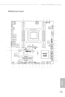
Motherboard Layout Fatal1ty X99M Killer/3.1 Series 1 2 3 45 USB 2.0 T: USB1 B: USB2 PS2 Keyboard /Mouse CLRC BTN1 USB SoundTM 2 CT4 CT3 CT2 CT1 1 FATAL TY PCIE2 Intel SATA3_1_4 X99 13 14 SATA3_2_5 X99M KILLER/3.1 SATAE_1 HD_AUDIO1 1 PCIE_PWR1 PCIE3 TBT1 COM1 1 1 USB5_6 - ASRock Fatal1ty X99M Killer/3.1 | Quick Installation Guide - Page 6
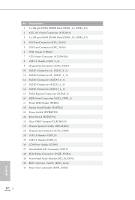
x 288-pin DDR4 DIMM Slots (DDR4_D1, DDR4_C1) 4 CPU Fan Connector (CPU_FAN1) 5 CPU Fan Connector (CPU_FAN2) 6 TPM Header (TPMS1) 7 ATX Power Connector (ATXPWR1) 8 USB 3.0 Header (USB3_5_6) 9 Chassis Fan Connector (CHA_FAN2) 10 SATA3 Connectors (S_SATA3_0_1) 11 SATA3 Connectors (S_SATA3_2_3) 12 SATA3 - ASRock Fatal1ty X99M Killer/3.1 | Quick Installation Guide - Page 7
I/O Panel 1 2 Fatal1ty X99M Killer/3.1 Series 57 3 4 68 16 15 14 13 12 11 10 9 No. Description 1 Fatal1ty Mouse Port (USB1) 2 USB 2.0 Port (USB2) No. Description 9 Microphone (Pink) 10 Optical SPDIF Out Port 3 LAN RJ-45 Port (Intel® I218V)* USB 3.1 Type-A Ports (ASMedia 11 ASM1142) ( - ASRock Fatal1ty X99M Killer/3.1 | Quick Installation Guide - Page 8
use the Rear Speaker, Central/Bass, and Front Speaker, or select "Realtek HDA Audio 2nd output" to use the front panel audio. *** he eSATA connector supports SATA with cables within 1 meters. he S_SATA3_3 connector is shared with the eSATA port. English 4 - ASRock Fatal1ty X99M Killer/3.1 | Quick Installation Guide - Page 9
CPU support list on ASRock's website as well. ASRock website http://www.asrock.com. 1.1 Package Contents • ASRock Fatal1ty X99M Killer/3.1 Series Motherboard (Micro ATX Form Factor) • ASRock Fatal1ty X99M Killer/3.1 Series Quick Installation Guide • ASRock Fatal1ty X99M Killer/3.1 Series Support CD - ASRock Fatal1ty X99M Killer/3.1 | Quick Installation Guide - Page 10
Chipset • Intel® X99 Memory • Quad Channel DDR4 Memory Technology • 4 x DDR4 DIMM Slots • Supports DDR4 3200+(OC)*/2933(OC)/2800(OC)/2400 (OC)/2133 non-ECC, un-bufered memory * Please refer to Memory Support List on ASRock's website for more information. (http://www.asrock.com/) • Supports non - ASRock Fatal1ty X99M Killer/3.1 | Quick Installation Guide - Page 11
Fatal1ty X99M Killer/3.1 Series LAN Rear Panel I/O • Supports Surge Protection (ASRock Full Spike Protection) • Supports Purity SoundTM 2 - Nichicon Fine Gold Series Audio Caps - 115dB SNR DAC with Diferential Ampliier - TI® NE5532 Premium Headset Ampliier (Supports up to 600 Ohms headsets) - - ASRock Fatal1ty X99M Killer/3.1 | Quick Installation Guide - Page 12
RAID (RAID 0, RAID 1, RAID 5, RAID 10 and Intel Rapid Storage 13), NCQ, AHCI, Hot Plug and ASRock HDD Saver Technology (S_SATA3_3 connector is shared with the eSATA port) (S_SATA3_2 connector is shared with Ultra M.2 Socket) * RAID is supported on SATA3_0 ~ SATA3_5 ports only. • 1 x SATA Express - ASRock Fatal1ty X99M Killer/3.1 | Quick Installation Guide - Page 13
Fatal1ty X99M Killer/3.1 Series Hardware Monitor OS Certiications • SMBIOS 2.3.1 Support • CPU, DRAM, PCH 1.05V, PCH 1.5V, required) * For detailed product information, please visit our website: http://www.asrock.com Please realize that there is a certain risk involved with overclocking, - ASRock Fatal1ty X99M Killer/3.1 | Quick Installation Guide - Page 14
Installation his is a Micro ATX form factor motherboard. Before you install the motherboard, study the coniguration of your chassis to ensure that the motherboard its into it. Pre-installation Precautions Take note of the following precautions before you install motherboard components or change any - ASRock Fatal1ty X99M Killer/3.1 | Quick Installation Guide - Page 15
Fatal1ty X99M Killer/3.1 Series 2.1 Installing the CPU 1. Before you insert the 2011 will be seriously damaged. 2. Unplug all power cables before installing the CPU. CAUTION: Please note that X99 platform is only compatible with the LGA 2011-3 socket, which is incompatible with the LGA 2011 socket ( - ASRock Fatal1ty X99M Killer/3.1 | Quick Installation Guide - Page 16
A 3 B 4 5 12 English - ASRock Fatal1ty X99M Killer/3.1 | Quick Installation Guide - Page 17
6 7 A B 8 Fatal1ty X99M Killer/3.1 Series A B English Please save and replace the cover if the processor is removed. he cover must be placed if you wish to return the motherboard for ater service. 13 - ASRock Fatal1ty X99M Killer/3.1 | Quick Installation Guide - Page 18
2.2 Installing the CPU Fan and Heatsink 1 2 CPU_FAN English 14 - ASRock Fatal1ty X99M Killer/3.1 | Quick Installation Guide - Page 19
Fatal1ty X99M Killer/3.1 Series 2.3 Installation of Memory Modules (DIMM) his motherboard provides four 288-pin DDR4 (Double Data Rate 4) DIMM slots, and supports Quad Channel Memory Technology. 1. For quad channel coniguration, you always need to install identical (the same brand, speed, size and - ASRock Fatal1ty X99M Killer/3.1 | Quick Installation Guide - Page 20
1 2 3 16 English - ASRock Fatal1ty X99M Killer/3.1 | Quick Installation Guide - Page 21
Fatal1ty X99M Killer/3.1 Series 2.4 Expansion Slots (PCI Express Slots) here are 3 PCI Express slots on the motherboard. Before installing an expansion better thermal environment, please connect a chassis fan to the motherboard's chassis fan connector (CHA_FAN1 or CHA_FAN2) when using multiple graphics cards - ASRock Fatal1ty X99M Killer/3.1 | Quick Installation Guide - Page 22
2.5 Jumpers Setup he illustration shows how jumpers are setup. When the jumper cap is placed on the pins, the jumper is "Short". If no jumper cap is placed on the pins, the jumper is "Open". he illustration shows a 3-pin jumper whose pin1 and pin2 are "Short" when a jumper cap is placed on these 2 - ASRock Fatal1ty X99M Killer/3.1 | Quick Installation Guide - Page 23
Fatal1ty X99M Killer/3.1 Series 2.6 Onboard Headers and Connectors Onboard headers and connectors are NOT jumpers. Do NOT place jumper caps over these headers and connectors. Placing jumper caps over the headers and connectors will cause permanent damage to the motherboard. System Panel Header (9- - ASRock Fatal1ty X99M Killer/3.1 | Quick Installation Guide - Page 24
SATA3_5 SATA3_4 SATA3_3 S_SATA3_3 S_SATA3_1 Please connect the chassis power LED to this header to indicate the system's power status. hese ten SATA3 connectors support SATA data cables for internal storage devices with up to 6.0 Gb/s data transfer rate. If the eSATA port on the rear I/O has been - ASRock Fatal1ty X99M Killer/3.1 | Quick Installation Guide - Page 25
Fatal1ty X99M Killer/3.1 Series USB 2.0 Headers (9-pin USB5_6) (see p.1, No. 25) (9-pin USB7_8) (see p.1, No. 24) USB_PWR PP+ GND DUMMY 1 GND P+ PUSB_PWR Besides four USB 2.0 ports on the I/O panel, there are two headers on this motherboard. Each USB 2.0 header can support two ports. USB 3.0 - ASRock Fatal1ty X99M Killer/3.1 | Quick Installation Guide - Page 26
it to Pin 1-3. 12 24 1 13 8 5 4 1 his motherboard provides a 24-pin ATX power connector. To use a 20-pin ATX power supply, please plug it along Pin 1 and Pin 13. his motherboard provides an 8-pin ATX 12V power connector. To use a 4-pin ATX power supply, please plug it along Pin 1 and Pin - ASRock Fatal1ty X99M Killer/3.1 | Quick Installation Guide - Page 27
Fatal1ty X99M Killer/3.1 Series PCIe Power Connector (4-pin PCIE_PWR1) (see p.1, No. 28) HDD Saver Connector 1 RRI#1 RRTS#1 GND TTXD1 DDCD#1 his COM1 header supports a serial port module. PCIRST# FRAME PCICLK his connector supports Trusted Platform Module (TPM) system, which can securely store - ASRock Fatal1ty X99M Killer/3.1 | Quick Installation Guide - Page 28
Selection Switch allows the system to boot from either BIOS A or BIOS B. his motherboard has two BIOS chips, a primary BIOS (BIOS_A) and a backup BIOS (BIOS_B), users are not able to update the backup BIOS manually. Users may refer to the BIOS LEDs (BIOS_A_LED or BIOS_ B_LED) to - ASRock Fatal1ty X99M Killer/3.1 | Quick Installation Guide - Page 29
Fatal1ty X99M Killer/3.1 Series 2.8 Dr. Debug Dr. Debug is used to provide code information, which makes troubleshooting even easier. could not be detected. Please re-install the memory and CPU. If the problem still exists, please install only one memory module or try using other memory modules - ASRock Fatal1ty X99M Killer/3.1 | Quick Installation Guide - Page 30
or try using other memory modules. d6 he VGA could not be recognized. Please clear CMOS and try re-installing the VGA card. If the problem still exists, please try installing the VGA card in other slots or use other VGA cards. d7 he Keyboard and mouse could not be recognized - ASRock Fatal1ty X99M Killer/3.1 | Quick Installation Guide - Page 31
Fatal1ty X99M Killer/3.1 Series 2.9 M.2_SSD (NGFF) Module Installation Guide he M.2, also known as the Next Generation Form Factor (NGFF), is a small size and versatile card edge connector that aims to replace mPCIe and mSATA. - ASRock Fatal1ty X99M Killer/3.1 | Quick Installation Guide - Page 32
hand. Step 4 Peel of the yellow protective ilm on the nut to be used. Hand tighten the standof into the desired nut location on the motherboard. Step 5 Align and gently insert the M.2 (NGFF) SSD module into the M.2 slot. Please be aware that the M.2 (NGFF) SSD module only its in one orientation - ASRock Fatal1ty X99M Killer/3.1 | Quick Installation Guide - Page 33
Fatal1ty X99M Killer/3.1 Series M.2_SSD (NGFF) Module Support List PCIe Interface SATA Interface Plextor PX-AG256M6e Intel SSDSCKGW080A401/80G Kingston RBU-SNS8400S3/180GD For the latest updates of M.2_SSD (NFGG) module support list, please visit our website for details: http://www.asrock - ASRock Fatal1ty X99M Killer/3.1 | Quick Installation Guide - Page 34
2.10 HDD Saver Cable Installation Guide The HDD Saver Connector on this motherboard allows you to switch on and off your SATA HDD(s). * he HDD Saver Connector supports up to two SATA HDDs. 2. Connect one end of the SATA data cable to a SATA port on the motherboard. hen connect the other end to your - ASRock Fatal1ty X99M Killer/3.1 | Quick Installation Guide - Page 35
und Prozessoren auf der ASRock-Webseite: ASRock-Website http://www.asrock.com. 1.1 Lieferumfang • ASRock Fatal1ty X99M Killer/3.1 Series - Motherboard (Micro-ATX-Formfaktor) • ASRock Fatal1ty X99M Killer/3.1 Series - Schnellinstallationsanleitung • ASRock Fatal1ty X99M Killer/3.1 Series - Support-CD - ASRock Fatal1ty X99M Killer/3.1 | Quick Installation Guide - Page 36
1.2 Technische Daten Plattform • Micro-ATX-Formfaktor • Leiterplatte mit hochdichtem Glasgewebe Prozessor • Unterstützt Intel® CoreTM i7- und Xeon®-18-Kern- Prozessorenfamilie für LGA 2011-3-Socket • Digipower-Design • 12-Leistungsphasendesign • Unterstützt Intel® Turbo Boost 2.0-Technologie • - ASRock Fatal1ty X99M Killer/3.1 | Quick Installation Guide - Page 37
Fatal1ty X99M Killer Fatal1ty-Mausport (USB 2.0) (unterstützt Schutz gegen elektrostatische Entladung (ASRock Full Spike Protection)) • 2 x USB 3.1-Typ-A-Ports (10,0-Gb/s) (ASMedia ASM1142) (unterstützt Schutz gegen elektrostatische Entladung (ASRock Full Spike Protect • 2 x USB 3.0-Ports (Intel® X99 - ASRock Fatal1ty X99M Killer/3.1 | Quick Installation Guide - Page 38
1, RAID 5, RAID 10, Intel Rapid Storage Technology 13), NCQ, AHCI, Hot-Plugging und ASRock HDD-Saver-Technologie (S_SATA3_3-Anschluss 4-polig, 1 x 3-polig) (Intel- ligente Lütergeschwindigkeitssteuerung) • 1 x Netzteillüteranschluss (3-polig) • 1 x 24-poliger ATX-Netzanschluss • 1 x 8-poliger 12-V- - ASRock Fatal1ty X99M Killer/3.1 | Quick Installation Guide - Page 39
Fatal1ty X99M Killer/3.1 Series BIOSFunktion Hardwareüberwachung Betriebssystem Zertiizierungen • 2 x 128-Mb-AMI-UEFI-Legal Netzteil erforderlich) * Detaillierte Produktinformationen inden Sie auf unserer Webseite: http://www.asrock.com Bitte beachten Sie, dass mit einer Übertaktung, zu der die - ASRock Fatal1ty X99M Killer/3.1 | Quick Installation Guide - Page 40
1.3 Jumpereinstellung Die Abbildung zeigt, wie die Jumper eingestellt werden. Wenn die JumperKappe auf den Kontakten angebracht ist, ist der Jumper „kurzgeschlossen". Wenn keine Jumper-Kappe auf den Kontakten angebracht ist, ist der Jumper „ofen". Die Abbildung zeigt einen 3-poligen Jumper, dessen - ASRock Fatal1ty X99M Killer/3.1 | Quick Installation Guide - Page 41
Fatal1ty X99M Killer/3.1 Series 1.4 Integrierte Stiftleisten und Anschlüsse Integrierte Stitleisten und Anschlüsse sind KEINE Jumper. Bringen Sie KEINE Jumper-Kappen an diesen Stitleisten und Anschlüssen - ASRock Fatal1ty X99M Killer/3.1 | Quick Installation Guide - Page 42
Kombination aus SATAE_1, SATA3_4 und SATA3_5. USB_PWR PP+ GND DUMMY 1 GND P+ PUSB_PWR Neben vier USB 2.0-Ports an der E/A-Blende beinden sich zwei Stitleisten an diesem Motherboard. Jede USB 2.0-Stitleiste kann zwei Ports unterstützen. Deutsch 38 - ASRock Fatal1ty X99M Killer/3.1 | Quick Installation Guide - Page 43
Fatal1ty X99M Killer/3.1 Series USB 3.0-Stitleisten (19-polig, USB3_5_6) (siehe S. 1, Nr. 8) Vbus IntA_PA_SSRXIntA_PA_SSRX+ USB 3.0-Ports an der E/ A-Blende beindet sich eine Stitleiste an diesem Motherboard. Jede USB 3.0-Stitleiste kann zwei Ports unterstützen. Audiostitleiste (Frontblende) (9- - ASRock Fatal1ty X99M Killer/3.1 | Quick Installation Guide - Page 44
schließen Sie es zur Nutzung eines 20-poligen ATX-Netzteils entlang Kontakt 1 und Kontakt 13 an. 8 5 Dieses Motherboard bietet einen 8-poligen ATX-12-V-Netzanschluss. 4 1 Bitte schließen Sie es zur Nutzung eines 4-poligen ATX-Netzteils entlang Kontakt 1 und Kontakt 5 an. GND +12V DETECT - ASRock Fatal1ty X99M Killer/3.1 | Quick Installation Guide - Page 45
Fatal1ty X99M Killer/3.1 Series hunderboltErweiterungskartenanschluss (5-polig, TBT1) (siehe S. 1, Nr. 27) Serieller-Port-Stitleiste (9-polig, COM1) (siehe S. 1, Nr. 26) TPM-Stitleiste (17-polig, TPMS1) (siehe S. 1, Nr. 6) Bitte verbinden Sie - ASRock Fatal1ty X99M Killer/3.1 | Quick Installation Guide - Page 46
. BIOS-Auswahlschalter (BIOS_SEL1) (siehe S. 1, Nr. 30) AB Der BIOS-Auswahlschalter ermöglicht dem System, von BIOS A oder BIOS B zu starten. Dieses Motherboard verfügt über zwei BIOS-Chips, ein primäres BIOS (BIOS_A) und ein Ausfall-BIOS (BIOS_B), die Sicherheit und Stabilität Ihres Systems - ASRock Fatal1ty X99M Killer/3.1 | Quick Installation Guide - Page 47
Internet de ASRock. Site Internet ASRock http://www.asrock.com. 1.1 Contenu de l'emballage • Carte mère ASRock Fatal1ty X99M Killer/3.1 Series (facteur de forme Micro ATX) • Guide d'installation rapide ASRock Fatal1ty X99M Killer/3.1 Series • CD d'assistance ASRock Fatal1ty X99M Killer/3.1 Series - ASRock Fatal1ty X99M Killer/3.1 | Quick Installation Guide - Page 48
• Facteur de forme Micro ATX • PCB en tissu de verre haute densité Processeur • Prends en charge les familles de processeurs Intel® CoreTM i7 et Xeon® pour le socket LGA 2011-3 • Conception Digi Power • Alimentation à 12 phases • Prend en charge la technologie Intel® Turbo Boost 2.0 • Prend - ASRock Fatal1ty X99M Killer/3.1 | Quick Installation Guide - Page 49
Fatal1ty X99M Killer/3.1 Series Réseau Connectique du panneau arrière • Protection contre les surtensions (Protection complète contre les pics ASRock) pics ASRock)) • 2 x ports USB 3.0 (Intel® X99) (Protection contre les décharges électrostatiques (Protection complète contre les pics ASRock)) • - ASRock Fatal1ty X99M Killer/3.1 | Quick Installation Guide - Page 50
1, RAID 5, RAID 10, technologies Intel Rapid Storage 13), NCQ, AHCI, « Hot Plug » et sauvegarde HDD ASRock (le connecteur S_SATA3_3 est partagé avec connecteur pour ventilateur d'alimentation (3 broches) • 1 x connecteur d'alimentation ATX 24 broches • 1 x connecteur d'alimentation 12 V 8 broches ( - ASRock Fatal1ty X99M Killer/3.1 | Quick Installation Guide - Page 51
Fatal1ty X99M Killer/3.1 Series Surveillance du matériel Système d'exploitation Certiications • Prend en des informations détaillées de nos produits, veuillez visiter notre site : http://www.asrock.com Il est important de signaler que l'overcloking présente certains risques, incluant des - ASRock Fatal1ty X99M Killer/3.1 | Quick Installation Guide - Page 52
1.3 Coniguration des cavaliers (jumpers) L'illustration ci-dessous vous renseigne sur la coniguration des cavaliers (jumpers). Lorsque le capuchon du cavalier est installé sur les broches, le cavalier est « courtcircuité ». Si le capuchon du cavalier n'est pas installé sur les broches, le cavalier - ASRock Fatal1ty X99M Killer/3.1 | Quick Installation Guide - Page 53
Fatal1ty X99M Killer/3.1 Series 1.4 Embases et connecteurs de la carte mère Les embases et connecteurs situés sur la carte NE SONT PAS des cavaliers. Ne placez JAMAIS de - ASRock Fatal1ty X99M Killer/3.1 | Quick Installation Guide - Page 54
Embase LED d'alimentation (PLED1 à 3 broches) (voir p.1, No. 17) 1 PLEDPLED+ PLED+ Connecteurs Serial ATA3 (S_SATA3_0_1: voir p.1, No. 10) (S_SATA3_2_3: voir p.1, No. 11) (SATA3_0_3: voir p.1, No. 12) (SATA3_1_4: voir p.1, No. 13) (SATA3_2_5: voir p.1, No. 14) S_SATA3_2 S_SATA3_0 S_SATA3_3 - ASRock Fatal1ty X99M Killer/3.1 | Quick Installation Guide - Page 55
Fatal1ty X99M Killer/3.1 Series Embases compatible avec la HDA pour fonctionner correctement. Veuillez suivre les instructions igurant dans notre manuel et dans le manuel du ch avec le panneau audio AC'97. E. Pour activer le micro frontal, sélectionnez l'onglet « FrontMic » du panneau de contr - ASRock Fatal1ty X99M Killer/3.1 | Quick Installation Guide - Page 56
broches) (voir p.1, No. 16) 52 12 24 1 13 8 5 4 1 GND +12V DETECT Cette carte mère est dotée d'un connecteur d'alimentation ATX à 24 broches. Pour utiliser une alimentation ATX à 20 broches, veuillez efectuer les branchements sur la Broche 1 et la Broche 13. Cette carte mère est dotée d'un - ASRock Fatal1ty X99M Killer/3.1 | Quick Installation Guide - Page 57
Fatal1ty X99M Killer/3.1 Series Connecteur hunderbolt AIC (TBT1 à 5 broches) (voir p.1, No. 27) Embase pour port série (COM1 à 9 broches) (voir p.1, No. 26) Embase TPM (TPMS1 à 17 broches) (voir p.1, No. 6) - ASRock Fatal1ty X99M Killer/3.1 | Quick Installation Guide - Page 58
1.5 Boutons intelligents La carte mère est équipée de quatre boutons intelligents : bouton de mise en marche, bouton de réinitialisation, bouton d'efacement CMOS et bouton de sélecteur de BIOS qui permettent aux utilisateurs d'allumer/éteindre le système, de réinitialiser le système, d'efacer les - ASRock Fatal1ty X99M Killer/3.1 | Quick Installation Guide - Page 59
Web di ASRock. Sito Web di ASRock http://www.asrock.com. 1.1 Contenuto della confezione • Scheda madre ASRock Fatal1ty X99M Killer/3.1 Series (Form Factor Micro ATX) • Guida all'installazione rapida di ASRock Fatal1ty X99M Killer/3.1 Series • CD di supporto di ASRock Fatal1ty X99M Killer/3.1 Series - ASRock Fatal1ty X99M Killer/3.1 | Quick Installation Guide - Page 60
1.2 Speciiche Piattaforma • Fattore di forma Micro ATX • PBC di ibra di vetro ad alta densità CPU • Supporta la famiglia di processori Intel® CoreTM i7 e Xeon® 18-Core per il socket LGA 2011-3 • Design Digi Power • Potenza a 12 fasi • Supporta la tecnologia Intel® Turbo Boost 2.0 • Supporta la - ASRock Fatal1ty X99M Killer/3.1 | Quick Installation Guide - Page 61
Fatal1ty X99M Killer/3.1 Series • Supporto protezione da sovratensione (protezione completa ASRock dai picchi di corrente) • Supporto di completa ASRock dai picchi di corrente)) • 2 x Porte USB 3.0 (Intel® X99) (supporto protezione da scariche elettrostatiche (ESD) (protezione completa ASRock dai - ASRock Fatal1ty X99M Killer/3.1 | Quick Installation Guide - Page 62
RAID 1, RAID 5, RAID 10, Intel Rapid Storage Technology 13), NCQ, AHCI, Hot Plug e tecnologia ASRock HDD Saver (il connettore S_SATA3_3 è • 1 x Connettore ventola alimentazione (3 pin) • 1 x Connettore alimentazione ATX 24 pin • 1 x Connettore alimentazione 12V 8-pin (connettore alimen- tazione - ASRock Fatal1ty X99M Killer/3.1 | Quick Installation Guide - Page 63
Fatal1ty X99M Killer/3.1 Series Funzione BIOS Hardware Monitor SO Certiicazioni • BIOS legale 2 x 128Mb AMI UEFI con informazioni dettagliate sul prodotto, visitare il nostro sito Web: http://www.asrock.com Prestare attenzione al potenziale rischio previsto nella pratica di overclocking, inclusa - ASRock Fatal1ty X99M Killer/3.1 | Quick Installation Guide - Page 64
1.3 Impostazione jumper L'illustrazione mostra in che modo vengono impostati i jumper. Quando il cappuccio del jumper è posizionato sui pin, il jumper è "cortocircuitato". Se sui pin non è posizionato alcun cappuccio del jumper, il jumper è "aperto". L'illustrazione mostra un jumper a 3 pin i cui - ASRock Fatal1ty X99M Killer/3.1 | Quick Installation Guide - Page 65
Fatal1ty X99M Killer/3.1 Series 1.4 Header e connettori sulla scheda Gli header e i connettori sulla scheda NON sono jumper. NON posizionare cappucci del jumper su questi header e connettori. Il posizionamento di - ASRock Fatal1ty X99M Killer/3.1 | Quick Installation Guide - Page 66
Connettori Serial ATA3 (S_SATA3_0_1: vedere pag. 1, n. 10) (S_SATA3_2_3: vedere pag.1, n. 11) (SATA3_0_3: vedere pag. 1, n. 12) (SATA3_1_4: vedere pag.1, n. 13) (SATA3_2_5: vedere pag. 1, n. 14) Connettore Serial ATA Express (SATAE_1: vedere pag.1, n. 15) Header USB 2.0 (USB5_6 a 9 pin) (vedere pag. - ASRock Fatal1ty X99M Killer/3.1 | Quick Installation Guide - Page 67
Fatal1ty X99M Killer/3.1 Series Header USB 3.0 (USB3_5_6 a 19 pin) (vedere pag. 1, n. 8) Vbus deve supportare HDA per funzionare correttamente. Seguire le istruzioni presenti nel nostro manuale e nel manuale dello chassis per installare il sistema. 2. Se si utilizza un pannello - ASRock Fatal1ty X99M Killer/3.1 | Quick Installation Guide - Page 68
di collegare una ventola della CPU a 3 pin, collegarla al pin 1-3. Questa scheda madre è dotata di un connettore di alimentazione ATX a 24 pin. Per utilizzare un'alimentazione ATX a 20 pin, collegarla lungo il pin1 e il pin 13. 8 5 Questa scheda madre è dotata di un connettore di alimentazione - ASRock Fatal1ty X99M Killer/3.1 | Quick Installation Guide - Page 69
Fatal1ty X99M Killer/3.1 Series Connettorehunderbolt AIC (TBT1 5-pin) (vedere pag. 1, n. 27) Header porta seriale (COM1 a 9 pin) (vedere pag. 1, n. 26) Header TPM (TPMS1 a 17 pin) (vedere pag. 1, n. 6) Collegare un - ASRock Fatal1ty X99M Killer/3.1 | Quick Installation Guide - Page 70
1.5 Interruttori intuitivi La scheda madre è dotata di quattro interruttori intuitivi: Interruttore d'alimentazione, interruttore di ripristino, interruttore Clear CMOS ed un interruttore di selezione BIOS che consentono di accendere/spegnere rapidamente il sistema, ripristinare il sistema, - ASRock Fatal1ty X99M Killer/3.1 | Quick Installation Guide - Page 71
. Sitio web de ASRock http://www.asrock.com. 1.1 Contenido del paquete • Placa base ASRock Fatal1ty X99M Killer/3.1 Series (Factor de forma Micro ATX) • Guía de instalación rápida de ASRock Fatal1ty X99M Killer/3.1 Series • CD de soporte de ASRock Fatal1ty X99M Killer/3.1 Series • 1 escudo panel - ASRock Fatal1ty X99M Killer/3.1 | Quick Installation Guide - Page 72
• Factor de forma Micro ATX • PCB de ibra de vidrio de alta densidad CPU • Admite la familia de procesadores Intel® CoreTM i7 y Xeon® 18-Core para el zócalo LGA 2011-3 • Diseño Digi Power • Diseño de 12 fases de alimentación • Compatible con la tecnología de Intel® Turbo Boost 2.0 • Admite - ASRock Fatal1ty X99M Killer/3.1 | Quick Installation Guide - Page 73
Fatal1ty X99M Killer/3.1 Series LAN Panel trasero I/O • Compatible con protección por sobretensión (protección ASRock Full Spike) • estática (protección ASRock Full Spike)) • 2 puertos USB 3.0 (Intel® X99) (compatible con protección contra electricidad estática (protección ASRock Full Spike)) • - ASRock Fatal1ty X99M Killer/3.1 | Quick Installation Guide - Page 74
RAID 5, RAID 10, Intel Rapid Storage Technology 13), NCQ, AHCI y conexión en caliente y tecnología de ahorro ASRock HDD (el conector 1 Conector de ventilador de alimentación (de 3 pines) • 1 Conector de alimentación ATX de 24 pines • 1 Conector de alimentación de 8 pines y 12V (conector de - ASRock Fatal1ty X99M Killer/3.1 | Quick Installation Guide - Page 75
Fatal1ty X99M Killer/3.1 Series Función del BIOS Monitor del hardware SO Certiicaciones • 2 BIOS Legal Para obtener más información acerca del producto, visite nuestro sitio web: http://www.asrock.com Tenga en cuenta que existen ciertos riesgos relacionados con el overclocking (sobreaceleración), - ASRock Fatal1ty X99M Killer/3.1 | Quick Installation Guide - Page 76
1.3 Instalación de los puentes La instalación muestra cómo deben instalarse los puentes. Cuando la tapa de puente se coloca en los pines, el puente queda "Corto". Si no coloca la tapa de puente en los pines, el puente queda "Abierto". La ilustración muestra un puente de 3 pines cuyo pin 1 y pin 2 - ASRock Fatal1ty X99M Killer/3.1 | Quick Installation Guide - Page 77
Fatal1ty X99M Killer/3.1 Series 1.4 Conectores y cabezales incorporados Los cabezales y conectores incorporados NO son puentes. NO coloque tapas de puente sobre estos cabezales y conectores. Si coloca tapas de puente - ASRock Fatal1ty X99M Killer/3.1 | Quick Installation Guide - Page 78
Cabezal de indicador LED de alimentación (PLED1 de 3 pines) (consulte la pág.1, N.º 17) 1 PLEDPLED+ PLED+ S_SATA3_2 S_SATA3_0 Conectores Serie ATA3 (S_SATA3_0_1: consulte la pág.1, N.º 10) (S_SATA3_2_3: (consulte la pág. 1, N.º 11) (SATA3_0_3: consulte la pág.1, N.º 12) (SATA3_1_4: consulte la - ASRock Fatal1ty X99M Killer/3.1 | Quick Installation Guide - Page 79
Fatal1ty X99M Killer/3.1 Series Cabezales USB 2.0 (USB5_6 de 9 pines) (consulte la pág.1, N.º 25) (USB7_8 de HDA para que pueda funcionar correctamente. Siga las instrucciones que se indican en nuestro manual y en el manual del chasis para instalar su sistema. 2. Si utiliza un panel de audio AC'97 - ASRock Fatal1ty X99M Killer/3.1 | Quick Installation Guide - Page 80
un ventilador de CPU de 3 pines, conéctelo al Pin 1-3. 12 24 1 13 Esta placa base contiene un conector de alimentación ATX de 24 pines. Para utilizar una toma de alimentación ATX de 20 pines, conéctela en los Pines del 1 al 13. 8 5 Esta placa base contiene un conector de aliment- aci - ASRock Fatal1ty X99M Killer/3.1 | Quick Installation Guide - Page 81
Fatal1ty X99M Killer/3.1 Series Conector de alimentación PCIe (PCIE_PWR1 de 4 pines) (consulte la pág.1, N.º 28) GND +12V DETECT Conecte a este conector un cable de alimentación molex de 4 pines cuando - ASRock Fatal1ty X99M Killer/3.1 | Quick Installation Guide - Page 82
de garantizar que el sistema funcione correctamente. Por cuestiones de seguridad, los usuarios no pueden actualizar el BIOS de copia de seguridad manual- mente. Los usuarios deberán consultar los indicadores LED del BIOS (BIOS_A_LED 78 o BIOS_B_LED) para identiicar qué BIOS está activado en ese - ASRock Fatal1ty X99M Killer/3.1 | Quick Installation Guide - Page 83
Fatal1ty X99M Killer/3.1 Series 1 ASRock Fatal1ty X99M Killer/3.1 Series ASRock ASRock BIOS ASRock ASRock VGA ASRock http://www.asrock.com. 1.1 ASRock Fatal1ty X99M Killer/3.1 Series Micro ATX ASRock Fatal1ty X99M Killer/3.1 Series ASRock Fatal1ty X99M Killer/3.1 Series • 1 1 x - ASRock Fatal1ty X99M Killer/3.1 | Quick Installation Guide - Page 84
• Digi Power design 12 Intel® Turbo Boost 2.0 Untied Overclocking Чипсет • Intel® X99 Память Quad Channel DDR4 Memory Technology • 4 DDR4 DIMM DDR4 3200+(OC)*/2933 (OC)/2800(OC)/2400(OC)/2133 Non-ECC Unbufered Memory Support List ASRock. (http://www.asrock.com RDIMM DIMM DDR4 - ASRock Fatal1ty X99M Killer/3.1 | Quick Installation Guide - Page 85
Fatal1ty X99M Killer/3.1 Series Аудио ЛВС • 7.1 HD Audio Realtek ALC1150) Premium Blu-ray Audio ASRock Full Spike Protection Purity Sound™ 2 Nichicon Fine Gold - 115 дБ SNR DAC TI® NE5532 Premium Headset Ampliier 600 Direct Drive DTS • 1 x Intel® I218V (Gigabit LAN PHY 10/100/ - ASRock Fatal1ty X99M Killer/3.1 | Quick Installation Guide - Page 86
• 10 x SATA3 6,0 RAID (RAID 0, RAID 1, RAID 5, RAID 10, Intel Rapid Storage Technology 13), NCQ, AHCI ASRock HDD Saver S_SATA3_3 eSATA S_SATA3_2 Ultra M.2 Socket) RAID SATA3_0 ~ SATA3_5. • 1 x SATA Express 10,0 с SATA3_4 и SATA3_5 1 x eSATA NCQ, AHCI и 1 x Ultra M.2 Socket - ASRock Fatal1ty X99M Killer/3.1 | Quick Installation Guide - Page 87
Fatal1ty X99M Killer/3.1 Series ACPI 1.1 SMBIOS 2.3.1 DRAM, PCH 1,05 В, PCH 1,5 В, VPPM 12V, +5V, +3,3V • Microsot® Windows® 8.1 32-bit / 8.1 64-bit / 8 32-bit / 8 64-bit / 7 32-bit / 7 64-bit • FCC, CE, WHQL ErP/EuP ErP/EuP) http://www.asrock.com BIOS Untied - ASRock Fatal1ty X99M Killer/3.1 | Quick Installation Guide - Page 88
1.3 3 1 и 2 CMOS (CLRCMOS1 1, № 21) CMOS CLRCMOS1 CMOS 15 2 и 3 на CLRCMOS1 на 5 CMOS BIOS CMOS BIOS CMOS CMOS. CMOS CMOS. 84 - ASRock Fatal1ty X99M Killer/3.1 | Quick Installation Guide - Page 89
Fatal1ty X99M Killer/3.1 Series 1.4 9 PANEL1 1, № 18) PLED+ PLEDPWRBTN# GND 1 GND RESET# GND HDLEDHDLED+ PWRBTN RESET PLED S1/S3 S4 S5 HDLED 85 - ASRock Fatal1ty X99M Killer/3.1 | Quick Installation Guide - Page 90
3 PLED1 1, № 17) Serial ATA3 (S_SATA3_0_1 1, № 10) (S_SATA3_2_3 1, № 11) (SATA3_0_3 1, № 12) (SATA3_1_4 1, № 13) (SATA3_2_5 1, № 14) S_SATA3_2 S_SATA3_0 1 PLEDPLED+ PLED+ S_SATA3_3 S_SATA3_1 SATA3 SATA 6,0 eSATA S_SATA3_3 Ultra M.2 Socket S_SATA3_2 SATA3_4, SATA3_5 SATA - ASRock Fatal1ty X99M Killer/3.1 | Quick Installation Guide - Page 91
Fatal1ty X99M Killer/3.1 Series USB 3.0 (19 USB3_5_6 1, № 8) Vbus IntA_PA_SSRXIntA_PA_SSRX+ GND IntA_PA_SSTXIntA_PA_SSTX+ GND IntA_PA_DIntA_PA_D+ Vbus IntA_PB_SSRXIntA_PB_SSRX+ GND IntA_PB_SSTXIntA_PB_SSTX+ GND IntA_PB_DIntA_PB_D+ Dummy 1 USB 3.0 USB 3.0 9 HD_ AUDIO1 1, № 29) GND - ASRock Fatal1ty X99M Killer/3.1 | Quick Installation Guide - Page 92
2) PCIe (4 PCIE_ PWR1 1, № 28) HDD Saver (4 SATA_ PWR_1 1, № 16) 4 3 21 CPU_FAN_SPEED FAN_SPEED_CONTROL GND FAN_VOLTAGE FAN_SPEED 4 3 1-3. 12 24 1 13 24 20 ATX 1 13. 8 5 8 4 1 12 4 ATX, 1 5. GND +12V DETECT 4 Molex. HDD Saver. 88 - ASRock Fatal1ty X99M Killer/3.1 | Quick Installation Guide - Page 93
Fatal1ty X99M Killer/3.1 Series hunderbolt AIC (5 TBT1 1, № 27) AIC hunderbolt 5 GPIO). 9 COM1 1, № 26) RRXD1 DDTR#1 DDSR#1 CCTS#1 1 RRI#1 RRTS#1 GND TTXD1 DDCD#1 17 TPMS1 1, № 6) PCIRST# FRAME PCICLK Trusted Platform Module (TPM 89 - ASRock Fatal1ty X99M Killer/3.1 | Quick Installation Guide - Page 94
1.5 BIOS BIOS. PWRBTN 1, № 19) Power RSTBTN 1, № 20) Reset CMOS (CLRCBTN 3, № 15) CMOS CMOS. BIOS (BIOS_SEL1 1, № 30) AB BIOS BIOS A или BIOS B. BIOS BIOS (BIOS_A) и BIOS BIOS_B BIOS BIOS BIOS BIOS UEFI Secure Backup UEFI BIOS BIOS BIOS - ASRock Fatal1ty X99M Killer/3.1 | Quick Installation Guide - Page 95
site da ASRock. Site da ASRock http://www.asrock.com. 1.1 Conteúdo da embalagem • Placa Mãe ASRock Fatal1ty X99M Killer/3.1 Series (Fator de Forma Micro ATX) • Guia de Instalação Rápida da ASRock Fatal1ty X99M Killer/3.1 Series • CD de Suporte da ASRock Fatal1ty X99M Killer/3.1 Series • 1 x Painel - ASRock Fatal1ty X99M Killer/3.1 | Quick Installation Guide - Page 96
Especiicações Plataforma • Formato Micro ATX • Tecido de Vidro de Alta densidade PCB CPU • Suporta Família de Processadores Intel® CoreTM i7 e Xeon® 18- Core para o Soquete LGA 2011-3 • Design Digi Power • Design com 12 fases de alimentação • Suporta a tecnologia Intel® Turbo Boost 2.0 • Suporta - ASRock Fatal1ty X99M Killer/3.1 | Quick Installation Guide - Page 97
Fatal1ty X99M Killer/3.1 Series Português • Suporte áudio Blu-ray superior • Suporta proteção contra sobretensão (Proteção Total Contra Picos ASRock) • Suporta Purity Sound™ 2 - Capacitor de Áudio Série Ouro Fino Nichicon - 115dB SNR DAC com ampliicador diferencial - Ampliicador de Fone de Ouvido - ASRock Fatal1ty X99M Killer/3.1 | Quick Installation Guide - Page 98
, Tecnologia de Armazenamento Rápido Intel® 13), NCQ, AHCI e Conexão a Quente e Tecnologia Protetora de HDD ASRock (O conector S_SATA3_3 é compartilhada • 1 x conector ventilador alimentação (3 pinos) • 1 x conector alimentação ATX 24 pinos • 1 x Conector de energia 8-pinos 12V (Conector de energia - ASRock Fatal1ty X99M Killer/3.1 | Quick Installation Guide - Page 99
Fatal1ty X99M Killer/3.1 Series Funções da BIOS Monitor de hardware SO Certiicações • 2 Para obter informações detalhadas sobre o produto, por favor, visite o nosso site: http://www.asrock.com Por favor, observe que existe um certo risco envolvendo overclocking, incluindo o ajuste das deinições - ASRock Fatal1ty X99M Killer/3.1 | Quick Installation Guide - Page 100
1.3 Coniguração dos jumpers A imagem abaixo mostra como os jumpers são conigurados. Quando a tampa do jumper é colocada nos pinos, o jumper é "Curto". Se não for colocada uma tampa de jumper nos pinos, o jumper é "Aberto". A imagem mostra um jumper de 3 pinos cujos pino1 e pino2 estão "Curtos" - ASRock Fatal1ty X99M Killer/3.1 | Quick Installation Guide - Page 101
Fatal1ty X99M Killer/3.1 Series 1.4 Suportes e conectores onboard Os conectores e suportes onboard NÃO são jumpers. NÃO coloque tampas de jumpers sobre estes terminais e conectores. Colocar tampas de jumpers sobre os terminais e conectores - ASRock Fatal1ty X99M Killer/3.1 | Quick Installation Guide - Page 102
Suporte LED de alimentação (PLED1 de 3 pinos) (ver p.1, N.º 17) Conectores série ATA3 (S_SATA3_0_1: ver p.1, N.º 10) (S_SATA3_2_3: ver p.1 No. 11) (SATA3_0_3: ver p.1, N.º 12) (SATA3_1_4: ver p.1 No. 13) (SATA3_2_5: ver p.1 No. 14) S_SATA3_2 S_SATA3_0 1 PLEDPLED+ PLED+ SATA3_2 SATA3_1 SATA3_0 - ASRock Fatal1ty X99M Killer/3.1 | Quick Installation Guide - Page 103
Fatal1ty X99M Killer/3.1 Series Suportes USB 2.0 (USB5_6 de 9 pinos) (ver p.1, N.º 25) (USB7_8 de 9 pinos) chassi deverá suportar HDA para funcionar corretamente. Por favor, siga as instruções no nosso manual e no manual do chassi para instalar o seu sistema. 2. Se utilizar um painel de áudio AC'97 - ASRock Fatal1ty X99M Killer/3.1 | Quick Installation Guide - Page 104
conectar um ventilador da CPU de 3 pinos, por favor, conecte-o ao Pino 1-3. Esta placa-mãe inclui um conector de alimentação ATX de 24 pinos. Para utilizar uma fonte de alimentação ATX de 20 pinos, introduza-a no Pino 1 e Pino 13. 8 5 Esta placa-mãe inclui um conector de alimentação de 12V - ASRock Fatal1ty X99M Killer/3.1 | Quick Installation Guide - Page 105
Fatal1ty X99M Killer/3.1 Series Conector de Energia PCIe (PCIE_PWR1 4-pinos) (ver p.1, N.º 28) GND +12V DETECT Por favor conecte um cabo de alimentação molex de 4 pinos a este conector quando - ASRock Fatal1ty X99M Killer/3.1 | Quick Installation Guide - Page 106
1.5 Interruptores inteligentes A placa-mãe tem quatro chaves inteligentes: Chave liga/desliga, Chave de Reset, Chave para Limpar CMOS e uma Chave de Seleção da BIOS, que permite aos usuários rapidamente ligar/desligar o sistema, reiniciar o sistema, limpar os valores de CMOS ou inicializar de BIOS - ASRock Fatal1ty X99M Killer/3.1 | Quick Installation Guide - Page 107
listelerini de ASRock'ın web sitesinden bulabilirsiniz. ASRock web sitesi http://www.asrock.com. 1.1 Ambalaj İçeriği • ASRock Fatal1ty X99M Killer/3.1 Series Anakartı (Micro ATX Form Faktörü) • ASRock Fatal1ty X99M Killer/3.1 Series Hızlı Kurulum Kılavuzu • ASRock Fatal1ty X99M Killer/3.1 Series - ASRock Fatal1ty X99M Killer/3.1 | Quick Installation Guide - Page 108
Teknolojisini destekler Yonga kümesi • Intel® X99 Bellek • Dört Kanallı DDR4 Bellek Teknolojisi • 4 x DDR4 DIMM Yuvası • ECC olmayan, ara belleğe alınmamış DDR4 3200+(OC)*/ 2933(OC)/2800(OC)/2400(OC)/2133 belleği destekler * Ayrıntılı bilgi için ASRock'ın web sitesindeki Bellek Desteği Listesine - ASRock Fatal1ty X99M Killer/3.1 | Quick Installation Guide - Page 109
Fatal1ty X99M Killer/3.1 Series LAN Arka Panel I/O • Dalgalanma Koruması Destekler (ASRock Tam Ani Gerilim ASMedia ASM1142) (ESD Koruması Destekler (ASRock Tam Ani Gerilim Koruması)) • 2 x USB 3.0 Bağlantı Noktası (Intel® X99) (ESD Koruması Destekler (ASRock Tam Ani Gerilim Koruması)) • LED'e - ASRock Fatal1ty X99M Killer/3.1 | Quick Installation Guide - Page 110
RAID 5, RAID 10, Intel Rapid Storage Technology 13), NCQ, AHCI, Tak Çıkar ve ASRock Sabit Disk Kaydedici Teknolojisi destekler ) (Akıllı Fan Hızı Kontrolü) • 1 x Güç Fanı Bağlayıcısı (3 pimli) • 1 x 24 pim ATX Güç Bağlayıcısı • 1 x 8 pim 12V Güç Bağlayıcısı (Yüksek Yoğunluklu Güç Bağlayıcısı) • 1 x - ASRock Fatal1ty X99M Killer/3.1 | Quick Installation Guide - Page 111
Fatal1ty X99M Killer/3.1 Series BIOS Özelliği Donanım Monitörü OS Belgeler • Çok dilli GUI beslemesi gerek- lidir) * Detaylı ürün bilgisi için, lütfen web sitemizi ziyaret edin: http://www.asrock.com Lütfen, BIOS ayarlarını düzenleme, Bağımsız Hız Aşırtma Teknolojinin uygulanması ya da üçüncü - ASRock Fatal1ty X99M Killer/3.1 | Quick Installation Guide - Page 112
1.3 Bağlantı Teli Kurulumu Çizim, bağlantı tellerinin kurulumunu göstermektedir. Tel kapağı, pimlerin üzerine yerleştirildiğinde, tel "Kısa" olur. Pimlerin üzerinde tel kapağı bulunmadığında, tel "Kısa" olur. Çizim, pin1 ve pin2 alanları "Kısa" olan ve bu iki pim üzerinde bir bağlantı teli kapağı - ASRock Fatal1ty X99M Killer/3.1 | Quick Installation Guide - Page 113
Fatal1ty X99M Killer/3.1 Series 1.4 Ekli Bağlantılar ve Bağlayıcılar Ekli bağlantılar ve bağlayıcılar bağlantı teli değildir. Bağlantı teli - ASRock Fatal1ty X99M Killer/3.1 | Quick Installation Guide - Page 114
Türkçe Seri ATA3 Bağlayıcıları (S_SATA3_0_1: bkz. sf.1, No. 10) (S_SATA3_2_3: bkz. s.1 No. 11) (SATA3_0_3: bkz. sf.1, No. 12) (SATA3_1_4: bkz. s.1 No. 13) (SATA3_2_5: bkz. s.1 No. 14) Seri ATA Express Bağlayıcısı (SATAE_1) (bkz. sf.1, No. 15) USB 2.0 Bağlantıları (9-pin USB5_6) (bkz. sf.1, No. 25) - ASRock Fatal1ty X99M Killer/3.1 | Quick Installation Guide - Page 115
Fatal1ty X99M Killer/3.1 Series Türkçe USB 3.0 Bağlantıları (19-pin USB3_5_6) (bkz. sf.1, No. 8) Vbus IntA_PA_SSRXIntA_PA_SSRX+ GND IntA_PA_SSTXIntA_PA_SSTX+ GND IntA_PA_DIntA_PA_D+ Vbus IntA_PB_SSRXIntA_PB_SSRX+ GND IntA_PB_SSTXIntA_PB_SSTX+ GND IntA_PB_DIntA_PB_D+ Dummy 1 - ASRock Fatal1ty X99M Killer/3.1 | Quick Installation Guide - Page 116
bkz sf.1, No. 31) Türkçe CPU Fan Bağlayıcıları (4-pin CPU_FAN1) (bkz sf.1, No. 4) (3-pin CPU_FAN2) (bkz sf.1, No. 5) ATX Güç Bağlayıcısı (24-pin ATXPWR1) (bkz. sf.1, No. 7) ATX 12V Güç Bağlayıcısı (8-pin ATX12V1) (bkz. sf.1, No. 2) PCIe Güç Bağlayıcısı (4 pimli PCIE_PWR1) (bkz. sf.1, No. 28) Sabit - ASRock Fatal1ty X99M Killer/3.1 | Quick Installation Guide - Page 117
Fatal1ty X99M Killer/3.1 Series hunderbolt AIC Bağlayıcısı (5 pimli TBT1) (bkz. sf.1, No. 27) Seri Bağlantı Noktası Bağlantısı (9-pin COM1) (bkz. sf.1, No. 26) TPM bağ - ASRock Fatal1ty X99M Killer/3.1 | Quick Installation Guide - Page 118
1.5 Akıllı Anahtar Anakartta dört adet akıllı düğme bulunur: Güç Düğmesi, Sıfırlama Düğmesi, CMOS Temizleme Düğmesi ve bir BIOS Seçim Anahtarı kullanıcıların sistemi hızlı bir şekilde açıp kapatmalarını, sistemi sıfırlamalarını, CMOS değerlerini temizlemelerini ya da farklı BIOS'tan yüklemelerini sa - ASRock Fatal1ty X99M Killer/3.1 | Quick Installation Guide - Page 119
한국어 Fatal1ty X99M Killer/3.1 Series 1 개요 ASRock Fatal1ty X99M Killer/3.1 Series ASRock ASRock BIOS ASRock ASRock VGA 카드와 CPU ASRock http://www.asrock.com. 1.1 • ASRock Fatal1ty X99M Killer/3.1 Series Micro ATX ASRock Fatal1ty X99M Killer/3.1 Series ASRock Fatal1ty X99M Killer/3.1 - ASRock Fatal1ty X99M Killer/3.1 | Quick Installation Guide - Page 120
1.2 규격 플랫폼 CPU • Micro ATX PCB • LGA 2011-3 소켓용 Intel® CoreTM i7 및 Xeon® 18 • Digi 12 Intel® Turbo Boost 2.0 Untied Overclocking • Intel® X99 • Quad Channel DDR4 DDR4 DIMM 슬롯 4 개 • DDR4 3200+(OC)*/2933(OC)/2800(OC)/2400(OC)/2133 비 -ECC ASRock http://www.asrock.com/) • 비 -ECC RDIMM - ASRock Fatal1ty X99M Killer/3.1 | Quick Installation Guide - Page 121
Fatal1ty X99M Killer/3.1 Series 한국어 오디오 7.1 CH HD Realtek ALC1150 Blu-ray ASRock Purity SoundTM 2 지원 - Nichicon Fine Gold 115dB SNR DAC - TI® NE5532 600 EMI PCB DTS LAN • 1 x Intel® I218V (Gigabit LAN PHY 10/100/1000 Mb/s) • 1 x Qualcomm® Atheros® KillerTM E2200 시리즈 (PCIE x1 - ASRock Fatal1ty X99M Killer/3.1 | Quick Installation Guide - Page 122
0, RAID 1, RAID 5, RAID 10, Intel 13), NCQ, AHCI ASRock HDD S_SATA3_3 eSATA S_SATA3_2 Ultra M.2 Socket * • 24 핀 ATX 1 개 • 8 핀 12V 1 HDD 1 개 • PCIe 1 1 개 • hunderbolt AIC 커넥터 1 개 • USB 2.0 헤더 2 개 (USB 2.0 포트 4 ESD (ASRock • USB 3.0 헤더 1 개 (USB 3.0 포트 2 ESD 보호 (ASRock • LED 탑재 - ASRock Fatal1ty X99M Killer/3.1 | Quick Installation Guide - Page 123
Fatal1ty X99M Killer/3.1 Series • CPU, DRAM, PCH 1.05V, PCH 1.5V • CPU CPU CPU CPU CPU 12V, +5V, +3.3V, CPU CPU 내 부 전압 OS 인증 • Microsot® Windows® 8.1 32 비트 / 8.1 64 비트 / 8 32 비트 / 8 64 비트 / 7 32 비트 / 7 64 비트 • FCC, CE, WHQL • ErP/EuP ErP/EuP 요) http://www.asrock.com BIOS - ASRock Fatal1ty X99M Killer/3.1 | Quick Installation Guide - Page 124
1.3 3 1 과 핀 2 Clear CMOS 점퍼 (CLRCMOS1) (1 21 기본값 Clear CMOS CLRCMOS1 CMOS 15 CLRCMOS1 의 핀 2 와 핀 3 을 5 BIOS CMOS BIOS CMOS CMOS CMOS Clear CMOS Clear CMOS 한 국 어 120 - ASRock Fatal1ty X99M Killer/3.1 | Quick Installation Guide - Page 125
한국어 Fatal1ty X99M Killer/3.1 Series 1.4 (9 핀 PANEL1) (1 18 PLED+ PLEDPWRBTN# GND 1 GND RESET# GND HDLEDHDLED+ PWRBTN RESET PLED LED LED S1/S3 LED S4 S5 LED HDLED LED LED LED - ASRock Fatal1ty X99M Killer/3.1 | Quick Installation Guide - Page 126
한 국 어 시리얼 ATA3 커넥터 (S_SATA3_0_1: (1 10 S_SATA3_2_3: (1 11 SATA3_0_3: (1 12 SATA3_1_4: (1 13 SATA3_2_5: (1 14 S_SATA3_2 S_SATA3_0 S_SATA3_3 S_SATA3_1 SATA3 6.0 Gb/s SATA I/O 의 eSATA S_SATA3_3 M.2 S_SATA3_2 SATA3_4 및 SATA3_5 는 SATA Express (SATAE_1 RAID 는 SATA3_0 ~ - ASRock Fatal1ty X99M Killer/3.1 | Quick Installation Guide - Page 127
Fatal1ty X99M Killer/3.1 Series 한국어 USB 3.0 헤더 (19 핀 USB3_5_6) (1 8 Vbus IntA_PA_SSRXIntA_PA_SSRX+ GND IntA_PA_SSTXIntA_PA_SSTX+ GND IntA_PA_DIntA_PA_D+ Vbus IntA_PB_SSRXIntA_PB_SSRX+ GND IntA_PB_SSTXIntA_PB_SSTX+ GND IntA_PB_DIntA_PB_D+ Dummy 1 I/O 패널에 USB 3.0 USB3.0 (9 핀 HD_AUDIO1) - ASRock Fatal1ty X99M Killer/3.1 | Quick Installation Guide - Page 128
4 핀 PCIE_PWR1) (1 28 HDD 4 핀 SATA_PWR_1) (1 16 4 3 21 CPU_FAN_SPEED FAN_SPEED_CONTROL GND FAN_VOLTAGE FAN_SPEED 12 24 1 13 4 핀 CPU 3 핀 CPU 1-3 24 핀 ATX 20 핀 ATX 1 과 핀 13 8 5 8 핀 ATX 12V 4 핀 4 1 ATX 1 과 핀 5 을 GND +12V DETECT 3 4 HDD HDD 124 - ASRock Fatal1ty X99M Killer/3.1 | Quick Installation Guide - Page 129
Fatal1ty X99M Killer/3.1 Series hunderbolt AIC 커넥터 (5 핀 TBT1) (1 27 hunderboltTM AIC 5 GPIO (9 핀 COM1) (1 26 RRXD1 DDTR#1 DDSR#1 CCTS#1 1 RRI#1 RRTS#1 GND TTXD1 DDCD#1 TPM 헤더 (17 핀 TPMS1) (1 6 PCIRST# FRAME PCICLK - ASRock Fatal1ty X99M Killer/3.1 | Quick Installation Guide - Page 130
한 국 어 1.5 CMOS BIOS CMOS BIOS PWRBTN) (1 19 Power RSTBTN) (1 20 Reset CMOS CLRCBTN) (3 15 CMOS CMOS BIOS BIOS_SEL1) (1 30 AB BIOS BIOS A 또는 BIOS B BIOS BIOS (BIOS_A BIOS (BIOS_B BIOS BIOS BIOS B BIOS UEFI Setup Utility UEFI BIOS - ASRock Fatal1ty X99M Killer/3.1 | Quick Installation Guide - Page 131
Fatal1ty X99M Killer/3.1 Series 1 ͡Ίʹ ASRock Fatal1ty X99M Killer/3.1 Series ASRock Fatal1ty X99M Killer/3.1 Series ASRock ASRock BIOS VGA CPU http://www.asrock.com. 1.1 • ASRock Fatal1ty X99M Killer/3.1 Series ATX • ASRock Fatal1ty X99M Killer/3.1 Series ASRock Fatal1ty X99M Killer - ASRock Fatal1ty X99M Killer/3.1 | Quick Installation Guide - Page 132
1.2 仕様 ATX PCB CPU • LGA 2011-3 Intel® CoreTM i7 ͓Αͼ Xeon® 18-Core 12 Intel 2.0 Untied Overclocking Λαϙʔτ • Intel® X99 DDR4 4 x DDR4 DIMM DDR4 3200+(OC)*/2933(OC)/2800(OC)/2400 (OC)/2133 ϊϯ ECC ASRock http://www.asrock.com/) • ϊϯ ECC RDIMM DIMM LGA 2011-3 Intel® Xeon - ASRock Fatal1ty X99M Killer/3.1 | Quick Installation Guide - Page 133
Fatal1ty X99M Killer/3.1 Series ASRock Purity Sound ™ 2 ʹରԠ - SN ൺ 115dB ͷ DAC TI® NE5532 600 Ohms EMI PCB DTS • 1 x Intel ESD ʢASRock 1 x Fatal1ty USB 2.0 ESDʣ ASRock 2 x USB 3.1 λΠϓ A ϙʔτ (10.0 Gb/s)(ASMedia ASM1142 ESD ASRock 2 x USB 3.0 ϙʔτ (Intel® X99 ESD ASRock LED ͖ - ASRock Fatal1ty X99M Killer/3.1 | Quick Installation Guide - Page 134
0ɺRAID 1ɺ RAID 5ɺRAID 10ɺIntel δʔ 13ɺ͓ΑͼʣɺNCQɺAHCI ͼɺASRock HDD ʢS_SATA3_3 ίωΫλ eSATA ʢS_SATA3_2 1 x 24 ϐϯ ATX 1 x 8 ϐϯ 12V 1 x HDD 1 x PCIe 1 x 1 x hunderbolt AIC 2 x USB 2.0 ϔομʔʢ4 ݸͷ USB 2.0 ESD ASRock 1 x USB 3.0 ϔομʔʢ2 ݸͷ USB 3.0 ESD ASRock 1 x Dr. Debug - ASRock Fatal1ty X99M Killer/3.1 | Quick Installation Guide - Page 135
日本語 Fatal1ty X99M Killer/3.1 Series BIOS ػೳ OS ೝূ • 2 x 128Mb AMI UEFI Legal BIOS GUI αϙʔτ ʢ1 x ϝΠϯ BIOS ͱ 1 x BIOSʣ͖ UEFI / 8 32 Ϗοτ / 8 64 Ϗοτ / 7 32 Ϗοτ / 7 64 Ϗοτ • FCCɺCEɺWHQL • ErP/EuP Readʢy ErP/EuP ready http://www.asrock.com BIOS Windows® 32 4GB Windows® 64 Windows - ASRock Fatal1ty X99M Killer/3.1 | Quick Installation Guide - Page 136
日本語 1.3 3 1 ͱϐϯ 2 CMOS CLRCMOS1) ʢp.1ɺNo. 21 ࢀরʣ σϑΥϧτ CMOS ͷ ΫϦΞ CLRCMOS1 ɺCMOS 15 CLRCMOS1 ͷϐ ϯ 2 ͱϐϯ 3 5 BIOS CMOS BIOS CMOS CMOS CMOS CMOS CMOS 132 - ASRock Fatal1ty X99M Killer/3.1 | Quick Installation Guide - Page 137
日本語 Fatal1ty X99M Killer/3.1 Series 1.4 9 ϐϯύωϧ 1ʣ ʢp.1ɺNo. 18 ࢀরʣ PLED+ PLEDPWRBTN# GND 1 GND RESET# GND HDLEDHDLED+ PWRBTN RESET PLED LED LED S1/S3 LED S4 S5 LED HDLED LED LED LED - ASRock Fatal1ty X99M Killer/3.1 | Quick Installation Guide - Page 138
日本語 SATA3_5 SATA3_4 SATA3_3 SATA3_2 SATA3_1 SATA3_0 γϦΞϧ ATA3 S_SATA3_0_1: p.1ɺNo. 10 ࢀরʣ (S_SATA3_2_3: p.1ɺNo. 11 ࢀরʣ (SATA3_0_3: p.1ɺNo. 12 ࢀরʣ (SATA3_1_4: p.1ɺNo. 13 ࢀরʣ (SATA3_2_5: p.1ɺNo. 14 ࢀরʣ S_SATA3_2 S_SATA3_0 S_SATA3_3 S_SATA3_1 ͜ΕΒ 10 SATA3 6.0 Gb/s SATA eSATA I/O S_ SATA3_3 - ASRock Fatal1ty X99M Killer/3.1 | Quick Installation Guide - Page 139
Fatal1ty X99M Killer/3.1 Series 日本語 USB 3.0 ϔομʔ ʢ19 ϐϯ USB3_5_6ʣ ʢp.1ɺNo. 8 ࢀরʣ Vbus IntA_PA_SSRXIntA_PA_SSRX+ GND IntA_PA_SSTXIntA_PA_SSTX+ GND IntA_PA_DIntA_PA_D+ Vbus IntA_PB_SSRXIntA_PB_SSRX+ GND IntA_PB_SSTXIntA_PB_SSTX+ GND IntA_PB_DIntA_PB_D+ Dummy 1 I/O ύωϧͷ 2 ͭͷ USB 3.0 1 USB 3.0 2 - ASRock Fatal1ty X99M Killer/3.1 | Quick Installation Guide - Page 140
ࢀরʣ HDD 4 ϐϯ SATA_PWR_1ʣ ʢp.1ɺNo. 16 ࢀরʣ 4 3 21 CPU_FAN_SPEED FAN_SPEED_CONTROL GND FAN_VOLTAGE FAN_SPEED 4 ϐ ϯ CPU 3 ϐϯͷ CPU 1-3 12 24 1 13 24 ϐ ϯ ATX 20 ϐϯͷ ATX 1 ͱ 13 8 5 8 ϐ ϯ ATX12V 4 ϐϯ 4 1 ͷ ATX ʹɺϐϯ 1 ͱ 5 ൪ʹ߹ GND +12V DETECT 3 4 HDD HDD 136 - ASRock Fatal1ty X99M Killer/3.1 | Quick Installation Guide - Page 141
Fatal1ty X99M Killer/3.1 Series hunderbolt AIC ίωΫλ ʢ5 ϐϯ TBT1ʣ ʢp.1ɺNo. 27 ࢀরʣ hunderboltTM AIC 5 GPIO 9 ϐϯ COM1ʣ ʢp.1ɺNo. 26 ࢀরʣ RRXD1 DDTR#1 DDSR#1 CCTS#1 1 RRI#1 RRTS#1 GND TTXD1 DDCD#1 TPM ϔομʔ ʢ17 ϐϯ TPMS1ʣ ʢp.1ɺNo. 6 ࢀরʣ - ASRock Fatal1ty X99M Killer/3.1 | Quick Installation Guide - Page 142
日本語 1.5 4 CMOS BIOS CMOS BIOS PWRBTNʣ ʢp.1ɺNo. 19 ࢀরʣ Power RSTBTNʣ ʢp.1ɺNo. 20 ࢀরʣ Reset ΫϦΞ CMOS εΠον ʢCLRCBTNʣ ʢp.3ɺNo. 15 ࢀরʣ ΫϦΞ CMOS CMOS BIOS BIOS_SEL1) ʢp.1ɺNo. 30 ࢀরʣ AB BIOS BIOS A ·ͨ BIOS B BIOʢS BIOS_A BIOʢS BIOS_Bʣͷ 2 ͭͷ BIOS BIOS BIOS - ASRock Fatal1ty X99M Killer/3.1 | Quick Installation Guide - Page 143
简体中文 Fatal1ty X99M Killer/3.1 Series 1 简介 Fatal1ty X99M Killer/3.1 BIOS VGA 卡和 CPU http://www.asrock.com. 1.1 • 华擎 Fatal1ty X99M Killer/3.1 Micro ATX Fatal1ty X99M Killer/3.1 Fatal1ty X99M Killer/3.1 1 x I/O 面板 • 1 x 华擎 SLI_Bridge 卡 • 2 x 串行 ATA (SATA 1 x HDD Saver 线 • 1 x Ultra M.2 - ASRock Fatal1ty X99M Killer/3.1 | Quick Installation Guide - Page 144
扩充槽 • Micro ATX LGA 2011-3 Socket 的 Intel® CoreTM i7 and Xeon® 18 12 相 CPU Intel® Turbo Boost 2.0 • Intel® X99 DDR4 4 x DDR4 DIMM DDR4 3200+(OC)*/2933(OC)/2800(OC)/2400 (OC)/2133 非 ECC Memory Support List http://www.asrock.com ECC RDIMM DIMM LGA 2011-3 Socket 中的 Intel® Xeon - ASRock Fatal1ty X99M Killer/3.1 | Quick Installation Guide - Page 145
Fatal1ty X99M Killer/3.1 Series 简体中文 音频 LAN 后面板 I/O 7.1 CH Realtek ALC1150 • 优质 Blu-ray 2 代 - Nichicon 115dB TI® NE5532 600 Ohm EMI PCB DTS 连接 • 1 x Intel 1 x Fatal1ty USB 2.0 ESD 2 x A 型 USB 3.1 端口 (10.0 Gb/s)(ASMedia ASM1142)(支 持防 ESD 2 x USB 3.0 端口 (Intel® X99 ESD 2 - ASRock Fatal1ty X99M Killer/3.1 | Quick Installation Guide - Page 146
6.0 Gb/s RAID(RAID 0、RAID 1、 RAID 5、RAID 10、Intel Rapid Storage Technology 13)、 NCQ、AHCI (S_SATA3_3 接口与 eSATA (S_SATA3_2 2 x CPU 1 x 4 针 , 1 x 3 针) • 2 x 1 x 4 针 , 1 x 3 1 x 3 针) • 1 x 24 针 ATX 1 x 8 针 12V 1 x 1 x PCIe 1 x 1 x 2 x USB 2.0 4 个 USB 2.0 ESD 静 1 x USB 3.0 2 个 USB 3.0 - ASRock Fatal1ty X99M Killer/3.1 | Quick Installation Guide - Page 147
简体中文 Fatal1ty X99M Killer/3.1 Series BIOS 硬件监控 • 2 x128Mb AMI UEFI Legal BIOS GUI 支持 (1 x 主 BIOS 和 1 x 备份 BIOS) UEFI 技术 • -bit / 7 32-bit / 7 64-bit • FCC、CE、WHQL • ErP/EuP ErP/EuP http://www.asrock.com BIOS 4GB Windows® 32-bit Windows® 64-bit XFast RAM 来利用 Windows 143 - ASRock Fatal1ty X99M Killer/3.1 | Quick Installation Guide - Page 148
简体中文 1.3 3 1 和针脚 2 清除 CMOS 跳线 (CLRCMOS1) (见第 1 页,第 21 个) 默认 清除 CMOS CLRCMOS1 CMOS 15 CLRCMOS1 2 和针脚 3 短接 5 BIOS CMOS BIOS CMOS CMOS CMOS 清除 CMOS CMOS 144 - ASRock Fatal1ty X99M Killer/3.1 | Quick Installation Guide - Page 149
简体中文 Fatal1ty X99M Killer/3.1 Series 1.4 9 针 PANEL1) ( 见第 1 页,第 18 个) PLED+ PLEDPWRBTN# GND 1 GND RESET# GND HDLEDHDLED+ PWRBTN RESET PLED LED LED S1/S3 LED S4 S5 LED 熄灭。 HDLED LED LED LED 亮起。 - ASRock Fatal1ty X99M Killer/3.1 | Quick Installation Guide - Page 150
简体中文 串行 ATA3 接口 (S_SATA3_0_1: 见第 1 页,第 10 个) (S_SATA3_2_3: 见第 1 页,第 11 个) (SATA3_0_3: 见第 1 页,第 12 个) (SATA3_1_4: 见第 1 页,第 13 个) (SATA3_2_5: 见第 1 页,第 14 个) S_SATA3_2 S_SATA3_0 S_SATA3_3 S_SATA3_1 这十个 SATA3 6.0 Gb/s SATA I/O 上的 eSATA S_SATA3_3 Ultra M.2 Socket S_SATA3_2 SATA3_4、SATA3_5 与 - ASRock Fatal1ty X99M Killer/3.1 | Quick Installation Guide - Page 151
Fatal1ty X99M Killer/3.1 Series USB 3.0 接脚 (19 针 USB3_5_6) (见第 1 页,第 8 个) Vbus IntA_PA_SSRXIntA_PA_SSRX+ GND IntA_PA_SSTXIntA_PA_SSTX+ GND IntA_PA_DIntA_PA_D+ Vbus IntA_PB_SSRXIntA_PB_SSRX+ GND IntA_PB_SSTXIntA_PB_SSTX+ GND IntA_PB_DIntA_PB_D+ Dummy 1 除 I/O USB 3.0 USB 3.0 9 针 HD_AUDIO1) - ASRock Fatal1ty X99M Killer/3.1 | Quick Installation Guide - Page 152
4- 针 PCIE_PWR1 1 页,第 28 个) 4- 针 SATA_PWR_1 1 页,第 16 个) 4 3 21 CPU_FAN_SPEED FAN_SPEED_CONTROL GND FAN_VOLTAGE FAN_SPEED 12 24 1 13 4 针 CPU 3 针 CPU 1-3。 24 针 ATX 20 针 ATX 1 和针脚 13 8 5 4 1 GND +12V DETECT 8 针 ATX 12V 4 针 ATX 1 和针脚 5 4 针 molex 请将 HDD Saver 148 - ASRock Fatal1ty X99M Killer/3.1 | Quick Installation Guide - Page 153
Fatal1ty X99M Killer/3.1 Series 5- 针 TBT1 1 页,第 27 个) 在安装 hunderbolt AIC 5 GPIO 9 针 COM1) (见第 1 页,第 26 个) RRXD1 DDTR#1 DDSR#1 CCTS#1 1 RRI#1 RRTS#1 GND TTXD1 DDCD#1 TPM 接脚 (17 针 TPMS1) (见第 1 页,第 6 个) PCIRST# FRAME PCICLK Trusted Platform - ASRock Fatal1ty X99M Killer/3.1 | Quick Installation Guide - Page 154
简体中文 1.5 4 CMOS 开关和 BIOS CMOS BIOS PWRBTN 1 页,第 19 个) Power RSTBTN 1 页,第 20 个) Reset 清除 CMOS 开关 (CLRCBTN 3 页,第 15 个) 清除 CMOS CMOS 值。 BIOS BIOS_SEL1 1 页,第 30 个) AB BIOS BIOS A 或 BIOS B BIOS BIOS (BIOS_A BIOS (BIOS_B BIOS BIOS BIOS B BIOS UEFI - ASRock Fatal1ty X99M Killer/3.1 | Quick Installation Guide - Page 155
简体中文 Fatal1ty X99M Killer/3.1 Series SJ/T 11364-2006 10 年。 圖一 部件名稱 鉛 (Pb) 鎘 (Cd) 汞 (Hg Cr(VI PBB PBDE) X O O O O O X O O O O O O SJ/T 11363-2006 X SJ/T 11363-2006 2002/95/EC 151 - ASRock Fatal1ty X99M Killer/3.1 | Quick Installation Guide - Page 156
繁體中文 1 簡介 Fatal1ty X99M Killer/3.1 BIOS VGA 卡及 CPU http://www.asrock.com 1.1 • 華擎 Fatal1ty X99M Killer/3.1 Micro ATX Fatal1ty X99M Killer/3.1 Fatal1ty X99M Killer/3.1 1 x I/O 1 x ASRock SLI_Bridge 卡 • 2 x Serial ATA (SATA 1 x HDD Saver 纜線 • 1 x Ultra M.2 插座) 152 - ASRock Fatal1ty X99M Killer/3.1 | Quick Installation Guide - Page 157
繁體中文 Fatal1ty X99M Killer/3.1 Series 1.2 規格 平台 CPU 擴充插槽 • Micro ATX • 支援 LGA 2011-3 插座的 Intel® CoreTM i7 與 Xeon® 18 Digi Power) • 12 Intel® Turbo Boost 2.0 • Intel® X99 DDR4 4 x DDR4 DIMM DDR4 3200+(OC)*/2933(OC)/2800(OC)/2400 (OC)/2133 非 ECC http:// www.asrock.com non-ECC RDIMM - ASRock Fatal1ty X99M Killer/3.1 | Quick Installation Guide - Page 158
E2200 ESD Energy Eicient Ethernet 802.3az • 支援 PXE • 1 x PS/2 1 x 光纖 SPDIF 1 x eSATA 接頭 • 3 x USB 2.0 ESD 1 x Fatal1ty USB 2.0 ESD 2 x USB 3.1 A 10.0 Gb/s)(ASMedia ASM1142)(支 援防 ESD 2 x USB 3.0 連接埠 (Intel® X99 ESD 2 x RJ-45 LAN LED(ACT/LINK LED 及 SPEED LED) • 1 x 清除 CMOS 開關 • HD - ASRock Fatal1ty X99M Killer/3.1 | Quick Installation Guide - Page 159
繁體中文 Fatal1ty X99M Killer/3.1 Series • 10 x SATA3 6.0 Gb/s RAID(RAID 0、RAID 1、RAID 5、RAID 10、Intel 13 )、NCQ、 x CPU 1 x 4-pin、1 x 3-pin) • 2 x 1 x 4-pin、1 x 3-pin 1 x 3-pin) • 1 x 24 pin ATX 1 x 8 pin 12V 1 x 1 x PCIe 1 x 1 x hunderbolt AIC 2 x USB 2.0 4 個 USB 2.0 ESD 1 x USB - ASRock Fatal1ty X99M Killer/3.1 | Quick Installation Guide - Page 160
度) • CPU 12V、+5V、+3.3V、CPU CPU 內部電壓 作業系統 • Microsot® Windows® 8.1 32 位元 / 8.1 64 位元 / 8 32 位元 / 8 64 位元 / 7 32 位元 / 7 64 位元 認證 • FCC、CE、WHQL • ErP/EuP Ready ErP/EuP ready http://www.asrock.com BIOS 156 在 Windows® 32 4GB。Windows® 64 XFast RAM 運用 Windows - ASRock Fatal1ty X99M Killer/3.1 | Quick Installation Guide - Page 161
繁體中文 Fatal1ty X99M Killer/3.1 Series 1.3 3-pin pin1 及 pin2 清除 CMOS 跳線 (CLRCMOS1 1 21) 預設 清除 CMOS CLRCMOS1 清除 CMOS 15 CLRCMOS1 上的 pin2 及 pin3 短路約 5 BIOS CMOS BIOS CMOS CMOS CMOS 清除 CMOS CMOS 157 - ASRock Fatal1ty X99M Killer/3.1 | Quick Installation Guide - Page 162
繁體中文 1.4 9-pin PANEL1 1 18) PLED+ PLEDPWRBTN# GND 1 GND RESET# GND HDLEDHDLED+ PWRBTN RESET PLED LED LED S1/S3 LED S4 S5) 時,LED HDLED LED LED LED LED LED 電源 LED 排針 (3-pin PLED1 1 17) 1 PLEDPLED+ PLED+ LED 158 - ASRock Fatal1ty X99M Killer/3.1 | Quick Installation Guide - Page 163
Serial ATA Express 接頭 (SATAE_1 1 15) SATA3_2 SATA3_1 SATA3_0 S_SATA3_2 S_SATA3_0 SATA3_5 SATA3_4 SATA3_3 S_SATA3_3 S_SATA3_1 Fatal1ty X99M Killer/3.1 Series 這十組 SATA3 SATA 6.0 Gb/s I/O 上 的 eSATA S_SATA3_3 Ultra M.2 S_SATA3_2 SATA3_4、SATA3_5 與 SATA Express 接頭 (SATAE_1 RAID 僅支援 SATA3_0 - ASRock Fatal1ty X99M Killer/3.1 | Quick Installation Guide - Page 164
繁體中文 USB 3.0 排針 (19-pin USB3_5_6 1 8) Vbus IntA_PA_SSRXIntA_PA_SSRX+ GND IntA_PA_SSTXIntA_PA_SSTX+ GND IntA_PA_DIntA_PA_D+ Vbus IntA_PB_SSRXIntA_PB_SSRX+ GND IntA_PB_SSTXIntA_PB_SSTX+ GND IntA_PB_DIntA_PB_D+ Dummy 1 除了 I/O USB 3.0 USB 3.0 9-pin HD_AUDIO1 1 29) GND PRESENCE# MIC_RET - ASRock Fatal1ty X99M Killer/3.1 | Quick Installation Guide - Page 165
繁體中文 Fatal1ty X99M Killer/3.1 Series (3-pin PWR_FAN1 1 31) CPU 4-pin CPU_FAN1 1 4) (3-pin CPU_FAN2 1 5) ATX 24-pin ATXPWR1 1 7) ATX 12V 8-pin ATX12V1 1 2) PCIe 4-pin PCIE_PWR1 1 28) 4-pin SATA_PWR_1 1 16) 4 3 21 CPU_FAN_SPEED FAN_SPEED_CONTROL GND FAN_VOLTAGE FAN_SPEED 4- - ASRock Fatal1ty X99M Killer/3.1 | Quick Installation Guide - Page 166
繁體中文 hunderbolt AIC 連接埠 (5-pin TBT1 1 27) 安裝 hunderboltTM AIC 5-pin GPIO 9-pin COM1 1 26) RRXD1 DDTR#1 DDSR#1 CCTS#1 1 RRI#1 RRTS#1 GND TTXD1 DDCD#1 TPM 標頭 (17-pin TPMS1 1 6) PCIRST# FRAME PCICLK TPM TPM 162 - ASRock Fatal1ty X99M Killer/3.1 | Quick Installation Guide - Page 167
繁體中文 Fatal1ty X99M Killer/3.1 Series 1.5 CMOS BIOS CMOS BIOS 開機。 PWRBTN 1 19) Power RSTBTN 1 20) Reset 清除 CMOS 開關 (CLRCBTN 3 15) 清除 CMOS CMOS 值。 BIOS BIOS_SEL1 1 30) AB BIOS BIOS A 或 BIOS B 開機。 BIOS BIOS ( - ASRock Fatal1ty X99M Killer/3.1 | Quick Installation Guide - Page 168
Ukuran Micro ATX • PCB Serat Kaca dengan Kerapatan Tinggi • Mendukung Kelompok Prosesor Intel® CoreTM i7 dan Xeon® 18-Core untuk Soket LGA 2011-3 • Desain Digi Power • Desain 12 Fase Daya • Mendukung Teknologi Intel® Turbo Boost 2.0 • Mendukung Teknologi Untied Overclocking • Intel® X99 • Teknologi - ASRock Fatal1ty X99M Killer/3.1 | Quick Installation Guide - Page 169
Fatal1ty X99M Killer/3.1 Series Bahasa Indonesia • Mendukung Audio Blu-ray Premium • Mendukung Perlindungan Lonjakan Arus (ASRock Full Spike Protection) • Mendukung Purity Sound™ 2 - Nichicon Fine Gold Series Audio Caps - 115dB SNR DAC dengan Ampliier Diferensial - TI® NE5532 Premium Headset - ASRock Fatal1ty X99M Killer/3.1 | Quick Installation Guide - Page 170
RAID 5, RAID 10, Intel Rapid Storage Technology 13), NCQ, AHCI, Hot Plug, dan ASRock HDD Saver Technology (konektor x 3-pin) (Kontrol Kecepatan Kipas Pintar) • 1 x Konektor Kipas Daya (3-pin) • 1 x Konektor Daya ATX 24 pin • 1 x Konektor Daya 12 V 8 pin (Konektor Daya dengan Kera- patan Tinggi) • 1 x - ASRock Fatal1ty X99M Killer/3.1 | Quick Installation Guide - Page 171
Bahasa Indonesia Fatal1ty X99M Killer/3.1 Series Fitur BIOS Monitor Perangkat Keras OS Sertiikasi • 2 x 128Mb AMI UEFI Untuk informasi tentang produk rinci, kunjungi situs web kami: http://www.asrock.com Perlu diketahui, overclocking memiliki risiko tertentu, termasuk menyesuaikan pengaturan - ASRock Fatal1ty X99M Killer/3.1 | Quick Installation Guide - Page 172
or want to know more about ASRock, you're welcome to visit ASRock's website at http://www.asrock.com; or you may contact your dealer for further information. For technical questions, please submit a support request form at http://www.asrock.com/support/tsd.asp ASRock Incorporation 2F., No.37, Sec
-
 1
1 -
 2
2 -
 3
3 -
 4
4 -
 5
5 -
 6
6 -
 7
7 -
8
-
9
-
10
-
11
-
12
-
13
-
14
-
15
-
16
-
17
-
18
-
19
-
20
-
21
-
22
-
23
-
24
-
25
-
26
-
27
-
28
-
29
-
30
-
31
-
32
-
33
-
34
-
35
-
36
-
37
-
38
-
39
-
40
-
41
-
42
-
43
-
44
-
45
-
46
-
47
-
48
-
49
-
50
-
51
-
52
-
53
-
54
-
55
-
56
-
57
-
58
-
59
-
60
-
61
-
62
-
63
-
64
-
65
-
66
-
67
-
68
-
69
-
70
-
71
-
72
-
73
-
74
-
75
-
76
-
77
-
78
-
79
-
80
-
81
-
82
-
83
-
84
-
85
-
86
-
87
-
88
-
89
-
90
-
91
-
92
-
93
-
94
-
95
-
96
-
97
-
98
-
99
-
100
-
101
-
102
-
103
-
104
-
105
-
106
-
107
-
108
-
109
-
110
-
111
-
112
-
113
-
114
-
115
-
116
-
117
-
118
-
119
-
120
-
121
-
122
-
123
-
124
-
125
-
126
-
127
-
128
-
129
-
130
-
131
-
132
-
133
-
134
-
135
-
136
-
137
-
138
-
139
-
140
-
141
-
142
-
143
-
144
-
145
-
146
-
147
-
148
-
149
-
150
-
151
-
152
-
153
-
154
-
155
-
156
-
157
-
158
-
159
-
160
-
161
-
162
-
163
-
164
-
165
-
166
-
167
-
168
-
169
-
170
-
171
-
172
 |
 |
Version 1.0
Published March 2015
Copyright©2015 ASRock INC. All rights reserved.
Copyright Notice:
No part of this documentation may be reproduced, transcribed, transmitted, or
translated in any language, in any form or by any means, except duplication of
documentation by the purchaser for backup purpose, without written consent of
ASRock Inc.
Products and corporate names appearing in this documentation may or may not
be registered trademarks or copyrights of their respective companies, and are used
only for identi±cation or explanation and to the owners’ bene±t, without intent to
infringe.
Disclaimer:
Speci±cations and information contained in this documentation are furnished for
informational use only and subject to change without notice, and should not be
constructed as a commitment by ASRock. ASRock assumes no responsibility for
any errors or omissions that may appear in this documentation.
With respect to the contents of this documentation, ASRock does not provide
warranty of any kind, either expressed or implied, including but not limited to
the implied warranties or conditions of merchantability or ±tness for a particular
purpose.
In no event shall ASRock, its directors, o²cers, employees, or agents be liable for
any indirect, special, incidental, or consequential damages (including damages for
loss of pro±ts, loss of business, loss of data, interruption of business and the like),
even if ASRock has been advised of the possibility of such damages arising from any
defect or error in the documentation or product.
His device complies with Part 15 of the FCC Rules. Operation is subject to the following
two conditions:
(1)
this device may not cause harmful interference, and
(2)
this device must accept any interference received, including interference that
may cause undesired operation.
CALIFORNIA, USA ONLY
He Lithium battery adopted on this motherboard contains Perchlorate, a toxic substance
controlled in Perchlorate Best Management Practices (BMP) regulations passed by the
California Legislature. When you discard the Lithium battery in California, USA, please
follow the related regulations in advance.
“Perchlorate Material-special handling may apply, see www.dtsc.ca.gov/hazardouswaste/
perchlorate”
ASRock Website: http://www.asrock.com