ASRock Fatal1ty X99X Killer/3.1 Quick Installation Guide
ASRock Fatal1ty X99X Killer/3.1 Manual
 |
View all ASRock Fatal1ty X99X Killer/3.1 manuals
Add to My Manuals
Save this manual to your list of manuals |
ASRock Fatal1ty X99X Killer/3.1 manual content summary:
- ASRock Fatal1ty X99X Killer/3.1 | Quick Installation Guide - Page 1
change without notice, and should not be constructed as a commitment by ASRock. ASRock assumes no responsibility for any errors or omissions that may appear in CALIFORNIA, USA ONLY he Lithium battery adopted on this motherboard contains Perchlorate, a toxic substance controlled in Perchlorate Best - ASRock Fatal1ty X99X Killer/3.1 | Quick Installation Guide - Page 2
Manufactured under license under U.S. Patent Nos: 5,956,674; 5,974,380; 6,487,535; 7,003,467 & other U.S. and worldwide patents issued & pending. DTS, the Symbol, & DTS and the Symbol together is a registered trademark & DTS Connect, DTS Interactive, DTS Neo:PC are trademarks of DTS, Inc. Product - ASRock Fatal1ty X99X Killer/3.1 | Quick Installation Guide - Page 3
the most highly anticipated matches of the year, winning in a 14 to (-1) killer victory. Competing at Quakecon 2004, I became the World's 1st Doom3 Champion by challenging matches and earning $25,000 for the victory. Since then Fatal1ty has traveled the globe to compete against the best in the world - ASRock Fatal1ty X99X Killer/3.1 | Quick Installation Guide - Page 4
everything gets really nice. It's all about getting the computer processing faster and allowing more luid movement around the maps. My vision for Fatal1ty hardware is to allow gamers to focus on the game without worrying about their equipment, something I've preached since I began competing. I don - ASRock Fatal1ty X99X Killer/3.1 | Quick Installation Guide - Page 5
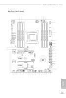
Fatal1ty X99X Killer/3.1 Series Motherboard Layout 12 3 4 56 7 USB 2.0 T: USB1 B: USB2 PS2 Keyboard /Mouse CLRC BTN1 USB 3.1 (Type-C) Vertical Type A USB CPU_FAN1 CPU_FAN2 ATX12V1 8 USB7 DDR4_D2 (64 bit, 288-pin - ASRock Fatal1ty X99X Killer/3.1 | Quick Installation Guide - Page 6
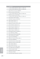
No. Description 1 2 x 288-pin DDR4 DIMM Slots (DDR4_A1, DDR4_B1) 2 2 x 288-pin DDR4 DIMM Slots (DDR4_A2, DDR4_B2) 3 ATX 12V Power Connector (ATX12V1) 4 CPU Fan Connector (CPU_FAN1) 5 2 x 288-pin DDR4 DIMM Slots (DDR4_D2, DDR4_C2) 6 CPU Fan Connector (CPU_FAN2) 7 2 x 288-pin DDR4 DIMM Slots (DDR4_D1, - ASRock Fatal1ty X99X Killer/3.1 | Quick Installation Guide - Page 7
No. Description 35 PCIe Power Connector (PCIE_PWR1) 36 Power Fan Connector (PWR_FAN1) Fatal1ty X99X Killer/3.1 Series English 3 - ASRock Fatal1ty X99X Killer/3.1 | Quick Installation Guide - Page 8
68 16 15 14 13 12 11 10 9 No. Description No. Description 1 Fatal1ty Mouse Port (USB1) 10 Optical SPDIF Out Port 2 USB 2.0 Port (USB2) 12 USB 3.0 Ports (USB3_12) 4 LAN RJ-45 Port (ASMedia ASM1074 hub) (Intel® I218V)* 13 eSATA Connector*** 5 Central / Bass (Orange) 14 USB 3.1 Type-C - ASRock Fatal1ty X99X Killer/3.1 | Quick Installation Guide - Page 9
Fatal1ty X99X Killer/3.1 Series * here are two LEDs on each LAN port. Please refer to the table below select "Realtek HDA Audio 2nd output" to use the front panel audio. *** he eSATA connector supports SATA with cables within 1 meters. he SSATA3_3 connector is shared with the eSATA port English 5 - ASRock Fatal1ty X99X Killer/3.1 | Quick Installation Guide - Page 10
and CPU support list on ASRock's website as well. ASRock website http://www.asrock.com. 1.1 Package Contents • ASRock Fatal1ty X99X Killer Series/3.1 Motherboard (ATX Form Factor) • ASRock Fatal1ty X99X Killer Series/3.1 Quick Installation Guide • ASRock Fatal1ty X99X Killer Series/3.1 Support CD - ASRock Fatal1ty X99X Killer/3.1 | Quick Installation Guide - Page 11
Fatal1ty X99X Killer/3.1 Series 1.2 Speciications Platform • ATX Form Factor • 2oz Copper PCB • High Density Glass Fabric PCB • Multiple Filter Cap (MFC) (Filter diferent noise by 3 diferent capacitors: DIP solid cap, POSCAP and MLCC) CPU • Supports Intel® CoreTM i7 and Xeon® 18-Core Processors - ASRock Fatal1ty X99X Killer/3.1 | Quick Installation Guide - Page 12
Supports up to 600 Ohms headsets) - Direct Drive Technology - EMI Shielding Cover - PCB Isolate Shielding • Supports DTS Connect LAN • 1 x Intel 2.0 Port (Supports ESD Protection (ASRock Full Spike Protection)) • 1 x Fatal1ty Mouse Port (USB 2.0) (Supports ESD Protection (ASRock Full Spike - ASRock Fatal1ty X99X Killer/3.1 | Quick Installation Guide - Page 13
Fatal1ty X99X Killer/3.1 Series • HD Audio Jacks: Rear Speaker / Central / Bass / Line in / Front Speaker / Microphone ASRock USB 3.1 Card/A+A • 2 x USB 3.1 Type-A Ports (10 Gb/s) (Supports ESD Protection (ASRock Full Spike Protection)) Storage • 10 x SATA3 6.0 Gb/s Connectors, support RAID ( - ASRock Fatal1ty X99X Killer/3.1 | Quick Installation Guide - Page 14
GUI support (1 x Main BIOS and 1 x Backup BIOS) • Supports Secure Backup UEFI Technology • ACPI 1.1 Compliant wake up events • SMBIOS 2.3.1 Support • For detailed product information, please visit our website: http://www.asrock.com Please realize that there is a certain risk involved with - ASRock Fatal1ty X99X Killer/3.1 | Quick Installation Guide - Page 15
Fatal1ty X99X Killer/3.1 Series Chapter 2 Installation his is an ATX form factor motherboard. Before you install the motherboard, study the coniguration of your chassis to ensure that the motherboard its into it. Pre-installation Precautions Take note of the following precautions before you install - ASRock Fatal1ty X99X Killer/3.1 | Quick Installation Guide - Page 16
situation is found. Otherwise, the CPU will be seriously damaged. 2. Unplug all power cables before installing the CPU. CAUTION: Please note that X99 platform is only compatible with the LGA 2011-3 socket, which is incompatible with the LGA 2011 socket (for X79 platform). 1 A B A 2 B 12 English - ASRock Fatal1ty X99X Killer/3.1 | Quick Installation Guide - Page 17
Fatal1ty X99X Killer/3.1 Series A 3 B 4 5 13 English - ASRock Fatal1ty X99X Killer/3.1 | Quick Installation Guide - Page 18
6 A B 7 A B 8 Please save and replace the cover if the processor is removed. he cover must be placed if you wish to return the motherboard for ater service. 14 English - ASRock Fatal1ty X99X Killer/3.1 | Quick Installation Guide - Page 19
Fatal1ty X99X Killer/3.1 Series 2.2 Installing the CPU Fan and Heatsink 1 2 CPU_FAN 15 English - ASRock Fatal1ty X99X Killer/3.1 | Quick Installation Guide - Page 20
Installation of Memory Modules (DIMM) his motherboard provides eight 284-pin DDR4 (Double Data Rate 4) DIMM slots, and supports Quad Channel Memory Technology. 1. For Populated Populated Populated Populated Populated Populated • Due to Intel® CPU spec deinition, please install the memory modules - ASRock Fatal1ty X99X Killer/3.1 | Quick Installation Guide - Page 21
Fatal1ty X99X Killer/3.1 Series 1 2 3 17 English - ASRock Fatal1ty X99X Killer/3.1 | Quick Installation Guide - Page 22
2.4 Expansion Slots (PCI Express Slots) here are 5 PCI Express slots and 1 mini-PCI Express slot on the motherboard. Before installing an expansion card, please make sure that the power supply is switched of or the power cord is unplugged. Please read the documentation - ASRock Fatal1ty X99X Killer/3.1 | Quick Installation Guide - Page 23
Fatal1ty X99X Killer/3.1 Series PCIe Slot Conigurations (For CPU with 28 PCIe lanes) Single Graphics x4 *3-Way SLITM Mode is not supported for CPU with 28 PCIe lanes. For a better thermal environment, please connect a chassis fan to the motherboard's chassis fan connector (CHA_FAN1, CHA_FAN2 - ASRock Fatal1ty X99X Killer/3.1 | Quick Installation Guide - Page 24
2.5 Jumpers Setup he illustration shows how jumpers are setup. When the jumper cap is placed on the pins, the jumper is "Short". If no jumper cap is placed on the pins, the jumper is "Open". he illustration shows a 3-pin jumper whose pin1 and pin2 are "Short" when a jumper cap is placed on these 2 - ASRock Fatal1ty X99X Killer/3.1 | Quick Installation Guide - Page 25
Fatal1ty X99X Killer/3.1 Series 2.6 Onboard Headers and Connectors Onboard headers and connectors are NOT jumpers. Do NOT place jumper caps over these headers and connectors. Placing jumper caps over the headers and connectors will cause permanent damage to the motherboard. System Panel Header (9- - ASRock Fatal1ty X99X Killer/3.1 | Quick Installation Guide - Page 26
: see p.1, No. 17) SATA3_0 SSATA3_2 SSATA3_0 SATA3_3 SSATA3_3 SSATA3_1 hese ten SATA3 connectors support SATA data cables for internal storage devices with up to 6.0 Gb/s data transfer rate. are two headers and one port on this motherboard. Each USB 2.0 header can support two ports. English - ASRock Fatal1ty X99X Killer/3.1 | Quick Installation Guide - Page 27
Fatal1ty X99X Killer/3.1 Series USB 3.0 Headers (19- two headers on this motherboard. Each USB 3.0 header can support two ports. Front supports Jack Sensing, but the panel wire on the chassis must support HDA to function correctly. Please follow the instructions in our manual and chassis manual - ASRock Fatal1ty X99X Killer/3.1 | Quick Installation Guide - Page 28
) (see p.1, No. 9) 12 24 ATX 12V Power Connector (8-pin ATX12V1) (see p.1, No. 3) 1 13 8 5 4 1 PCIe Power Connector (4-pin PCIE_PWR1) (see p.1, No. 35) his motherboard provides a 24-pin ATX power connector. To use a 20-pin ATX power supply, please plug it along Pin 1 and Pin 13. his - ASRock Fatal1ty X99X Killer/3.1 | Quick Installation Guide - Page 29
Fatal1ty X99X Killer/3.1 Series HDD Saver Connector (4-pin SATA_PWR_1) (see p.1, No. 23) hunderbolt AIC via the GPIO cable. RRXD1 DDTR#1 DDSR#1 CCTS#1 1 RRI#1 RRTS#1 GND TTXD1 DDCD#1 his COM1 header supports a serial port module. TPM Header (17-pin TPMS1) (see p.1, No. 33) 1 GN D SMB_CLK_MAIN - ASRock Fatal1ty X99X Killer/3.1 | Quick Installation Guide - Page 30
BIOS Selection Switch allows the system to boot from either BIOS A or BIOS B. his motherboard has two BIOS chips, a primary BIOS (BIOS_A) and a backup BIOS (BIOS_ B), users are not able to update the backup BIOS manually. Users may refer to the BIOS LEDs (BIOS_A_LED or BIOS_B_LED) to identify - ASRock Fatal1ty X99X Killer/3.1 | Quick Installation Guide - Page 31
Fatal1ty X99X Killer/3.1 Series 2.8 Dr. Debug Dr. Debug is used to provide code information, which makes troubleshooting even easier. could not be detected. Please re-install the memory and CPU. If the problem still exists, please install only one memory module or try using other memory modules - ASRock Fatal1ty X99X Killer/3.1 | Quick Installation Guide - Page 32
or try using other memory modules. d6 he VGA could not be recognized. Please clear CMOS and try re-installing the VGA card. If the problem still exists, please try installing the VGA card in other slots or use other VGA cards. d7 he Keyboard and mouse could not be recognized - ASRock Fatal1ty X99X Killer/3.1 | Quick Installation Guide - Page 33
Fatal1ty X99X Killer/3.1 Series 2.9 M.2_SSD (NGFF) Module Installation Guide he M.2, also known as the Next Generation Form Factor (NGFF), is a small size and versatile card edge connector that aims to replace mPCIe and mSATA. - ASRock Fatal1ty X99X Killer/3.1 | Quick Installation Guide - Page 34
hand. Step 4 Peel of the yellow protective ilm on the nut to be used. Hand tighten the standof into the desired nut location on the motherboard. Step 5 Align and gently insert the M.2 (NGFF) SSD module into the M.2 slot. Please be aware that the M.2 (NGFF) SSD module only its in one orientation - ASRock Fatal1ty X99X Killer/3.1 | Quick Installation Guide - Page 35
Fatal1ty X99X Killer/3.1 Series M.2_SSD (NGFF) Module Support List PCIe Interface SATA Interface Plextor PX-G512M6e Plextor Intel SSDSCKGW080A401/80G Kingston RBU-SM2280S3/120G For the latest updates of M.2_SSD (NFGG) module support list, please visit our website for details: http://www.asrock - ASRock Fatal1ty X99X Killer/3.1 | Quick Installation Guide - Page 36
2.10 HDD Saver Cable Installation Guide The HDD Saver Connector on this motherboard allows you to switch on and off your SATA HDD(s). * he HDD Saver Connector supports up to two SATA HDDs. 2. Connect one end of the SATA data cable to a SATA port on the motherboard. hen connect the other end to your - ASRock Fatal1ty X99X Killer/3.1 | Quick Installation Guide - Page 37
Fatal1ty X99X Killer/3.1 Series 2.11 ASRock USB 3.1 Card/A+A Installation Guide Speciications Platform • Size: 3.1-in x 3.2-in • 2 x USB 3.1 Type-A Ports (Supports ESD Protection (ASRock Full Spike Protection)) *Sleep Mode (S3/S4/S5) Wake-up function is not supported. • 1 x 4-pin Power Connector - ASRock Fatal1ty X99X Killer/3.1 | Quick Installation Guide - Page 38
external USB 3.1 ports which support transfer rates up to 10 Gbps. Follow the simple steps below to install the ASRock USB 3.1 Card/A+A. Step 1 x8 or x16 PCI Express slot on your motherboard and remove its slot bracket. *To maximize the performance of ASRock USB 3.1/A+A, it is highly recommended to - ASRock Fatal1ty X99X Killer/3.1 | Quick Installation Guide - Page 39
ASRock-Webseite: ASRock-Website http://www.asrock.com. 1.1 Lieferumfang • ASRock Fatal1ty X99X Killer Series - Motherboard (ATX-Formfaktor) • ASRock Fatal1ty X99X Killer Series - Schnellinstallationsanleitung • ASRock Fatal1ty X99X Killer Series - Support-CD • 1 x E/A-Blendenabschirmung • 1 x ASRock - ASRock Fatal1ty X99X Killer/3.1 | Quick Installation Guide - Page 40
Sie in der Speicherkompatibilitätsliste auf der ASRock-Webseite. (http:// www.asrock.com/) • Unterstützt ECC-lose RDIMM (Registered-DIMM) • Unterstützt DDR4 ECC, ungepuferter Speicher/RDIMM mit Intel® Xeon®-Prozessoren der E5-Serie im LGA 2011-3-Sockel • Systemspeicher, max. Kapazität: 128GB (siehe - ASRock Fatal1ty X99X Killer/3.1 | Quick Installation Guide - Page 41
Fatal1ty X99X Killer/3.1 Series Audio LAN Rückblende, E/A * Bei Installation einer CPU mit 28 Lanes wird Dreiwege-SLI™ nicht unterstützt. • 7.1-Kanal-HD-Audio mit Inhaltsschutz (Realtek ALC1150Audiocodec) • Erstklassige Blu-ray-Audiounterstützung • Unterstützt Überspannungsschutz (ASRock x Intel® - ASRock Fatal1ty X99X Killer/3.1 | Quick Installation Guide - Page 42
Full Spike Protection) Speicher • 10 x SATA-III-6,0-Gb/s-Anschlüsse per Intel® X99, unterstützt RAID (RAID 0, RAID 1, RAID 5, RAID 10, Intel Rapid Storage Technology 13), NCQ, AHCI, Hot-Plugging und ASRock HDD-Saver-Technologie (SSATA3_3-Anschluss wird mit eSATA-Port geteilt) (SSATA3_2-Anschluss - ASRock Fatal1ty X99X Killer/3.1 | Quick Installation Guide - Page 43
Fatal1ty X99X Killer/3.1 Series • 1 x hunderbolt-Erweiterungskartenanschluss • 2 x USB 2.0-Stitleisten (unterstützen 4 USB 2.0-Ports) (un- terstützt Schutz gegen elektrostatische Entladung (ASRock Full Spike Protection)) • 1 x Vertikal, Typ A, USB 2.0 • 2 x USB 3.0-Stitleisten (unterstützen 4 USB - ASRock Fatal1ty X99X Killer/3.1 | Quick Installation Guide - Page 44
für die Systemnutzung reservierten Speichers unter Windows®-Betriebssystemen mit 32 Bit weniger als 4 GB betragen. Windows®-Betriebssysteme mit 64 Bit haben keine derartigen Beschränkungen. Mit ASRock XFast RAM können Sie den Speicher einsetzen, den Windows® nicht nutzen kann. 40 Deutsch - ASRock Fatal1ty X99X Killer/3.1 | Quick Installation Guide - Page 45
Fatal1ty X99X Killer/3.1 Series 1.3 Jumpereinstellung Die Abbildung zeigt, wie die Jumper eingestellt werden. Wenn die JumperKappe auf den Kontakten angebracht ist, ist der Jumper „kurzgeschlossen". Wenn keine Jumper- - ASRock Fatal1ty X99X Killer/3.1 | Quick Installation Guide - Page 46
an diesen Stitleisten und Anschlüssen an. Durch Anbringen von Jumper-Kappen an diesen Stitleisten und Anschlüssen können Sie das Motherboard dauerhat beschädigen. Systemblende-Stitleiste (9-polig, PANEL1) (siehe S. 1, Nr. 21) PLED+ PLEDPWRBTN# GND 1 GND RESET# GND HDLEDHDLED+ Verbinden Sie - ASRock Fatal1ty X99X Killer/3.1 | Quick Installation Guide - Page 47
Fatal1ty X99X Killer/3.1 Series Betrieb-LED-Stitleiste (3-polig, PLED1) (siehe S. 1, Nr. 19) Serial-ATA-IIIAnschlüsse (SSATA3_0_1: siehe S. 1, Nr. 13) (SSATA3_2_3: siehe S. 1, Nr. 14) (SATA3_0_3: siehe S. 1, Nr. 15) ( - ASRock Fatal1ty X99X Killer/3.1 | Quick Installation Guide - Page 48
1, Nr. 8) Neben zwei USB 2.0-Ports USB_PWR P- an der E/A-Blende P+ GND beinden sich zwei DUMMY Stitleisten und ein Port an 1 diesem Motherboard. Jede GND P+ PUSB_PWR USB 2.0-Stitleiste kann zwei Ports unterstützen. USB 3.0-Stitleisten (19-polig, USB3_5_6) (siehe S. 1, Nr. 11) (19-polig - ASRock Fatal1ty X99X Killer/3.1 | Quick Installation Guide - Page 49
Fatal1ty X99X Killer/3.1 Series Gehäuse- und Netzteillüteranschlüsse (4-polig, CHA_FAN1) (siehe S. 1, Nr. 26) (3-polig, CHA_FAN2) ( , verbinden Sie ihn bitte mit Kontakt 1 bis 3. 12 24 1 13 Dieses Motherboard bietet einen 24-poligen ATX-Netzanschluss. Bitte schließen Sie es zur Nutzung eines - ASRock Fatal1ty X99X Killer/3.1 | Quick Installation Guide - Page 50
PCIe-Netzanschluss (4-polig, PCIE_PWR1) (siehe S. 1, Nr. 35) HDD-Saver-Anschluss (4-polig, SATA_PWR_1) (siehe S. 1, Nr. 23) Bitte verbinden Sie ein 4-poliges Molex-Netzkabel mit diesem Anschluss, wenn mehr als drei PCI Express-Karten installiert sind. Bitte verbinden Sie zum 1 Verwalten des - ASRock Fatal1ty X99X Killer/3.1 | Quick Installation Guide - Page 51
Fatal1ty X99X Killer/3.1 Series 1.5 Intelligente Schalter Das Motherboard hat vier intelligente Schalter: Ein-/Ausschalter, BIOS-Auswahlschalter ermöglicht dem System, von BIOS A oder BIOS B zu starten. Dieses Motherboard verfügt über zwei BIOS-Chips, ein primäres BIOS (BIOS_A) und ein Ausfall- - ASRock Fatal1ty X99X Killer/3.1 | Quick Installation Guide - Page 52
site Internet de ASRock. Site Internet ASRock http://www.asrock.com. 1.1 Contenu de l'emballage • Carte mère ASRock Fatal1ty X99X Killer Series (facteur de forme ATX) • Guide d'installation rapide ASRock Fatal1ty X99X Killer Series • CD d'assistance ASRock Fatal1ty X99X Killer Series • 1 x panneau - ASRock Fatal1ty X99X Killer/3.1 | Quick Installation Guide - Page 53
Fatal1ty X99X Killer/3.1 Series 1.2 Spéciications Plateforme • Facteur de forme ATX • PCB www.asrock.com/) • Prend en charge RDIMM non-ECC (RDIMM enregistrée) • Prend en charge DDR4 ECC, la mémoire sans mise en tampon/RDIMM avec la série de processeurs Intel® Xeon® E5 sur le socket LGA 2011-3 - ASRock Fatal1ty X99X Killer/3.1 | Quick Installation Guide - Page 54
EMI - Blindage isolant PCB • Prend en charge DTS Connect Réseau • 1 x Intel® I218V (Gigabit LAN PHY 10/100/1000 Mo/s) • 1 x Qualcomm® Atheros® KillerTM ASRock)) • 1 x port souris Fatal1ty (USB 2.0) (Protection contre les décharges électrostatiques (Protection complète contre les pics ASRock - ASRock Fatal1ty X99X Killer/3.1 | Quick Installation Guide - Page 55
Fatal1ty X99X Killer/3.1 Series carte USB 3.1 ASRock/A+A Stockage Connectique • 1 x bouton Clear CMOS • Connecteurs jack audio HD : Haut-parleur arrière / central / basses / entrée ligne / haut-parleur avant / microphone • 2 ports USB 3.1 Type A (10 Gb/s) (Prend en charge la protection DES (ASRock - ASRock Fatal1ty X99X Killer/3.1 | Quick Installation Guide - Page 56
Certiications • 2 x embases USB 3.0 (4 ports USB 3.0 pris en charge) (Protection contre les décharges électrostatiques (Protection complète contre les pics ASRock)) • 1 x Dr Debug avec témoin LED • 1 x bouton de mise en marche avec témoin LED • 1 x bouton de réinitialisation avec témoin LED - ASRock Fatal1ty X99X Killer/3.1 | Quick Installation Guide - Page 57
Fatal1ty X99X Killer/3.1 Series Il est important de signaler que l'overcloking présente certains risques, incluant des limitation ne concerne pas les systèmes d'exploitation Windows® 64-bit. Vous pouvez utiliser ASRock XFast RAM pour utiliser la mémoire dont Windows® ne peut se servir. 53 Français - ASRock Fatal1ty X99X Killer/3.1 | Quick Installation Guide - Page 58
1.3 Coniguration des cavaliers (jumpers) L'illustration ci-dessous vous renseigne sur la coniguration des cavaliers (jumpers). Lorsque le capuchon du cavalier est installé sur les broches, le cavalier est « courtcircuité ». Si le capuchon du cavalier n'est pas installé sur les broches, le cavalier - ASRock Fatal1ty X99X Killer/3.1 | Quick Installation Guide - Page 59
Fatal1ty X99X Killer/3.1 Series 1.4 Embases et connecteurs de la carte mère Les embases et connecteurs situés sur la carte NE SONT PAS des cavaliers. Ne placez JAMAIS de - ASRock Fatal1ty X99X Killer/3.1 | Quick Installation Guide - Page 60
Connecteurs Serial ATA3 (SSATA3_0_1: (voir p.1, No. 13) (SSATA3_2_3: voir p.1, No. 14) (SATA3_0_3: (voir p.1, No. 15) (SATA3_1_4: voir p.1, No. 16) (SATA3_2_5: (voir p.1, No. 17) SATA3_0 SSATA3_2 SSATA3_0 SATA3_3 SSATA3_3 SSATA3_1 Ces dix connecteurs SATA3 sont compatibles avec les câbles de - ASRock Fatal1ty X99X Killer/3.1 | Quick Installation Guide - Page 61
Fatal1ty X99X Killer/3.1 Series Embases USB 3.0 (USB3_5_6 à 19 broches) (voir p.1, No. 11) (USB3_7_8 à 19 é du châssis doit être compatible avec la HDA pour fonctionner correctement. Veuillez suivre les instructions igurant dans notre manuel et dans le manuel du châssis pour installer votre système. - ASRock Fatal1ty X99X Killer/3.1 | Quick Installation Guide - Page 62
(CHA_FAN3 à 3 broches) (voir p.1, No. 12) (PWR_FAN1 à 3 broches) (voir p.1, No. 36) GND FAN_VOLTAGE CHA_FAN_SPEED Connecteurs du ventilateur du processeur (CPU_FAN1 à 4 broches) (voir p.1, No. 4) (CPU_FAN2 à 3 broches) (voir p.1, No. 6) Connecteur d'alimentation ATX (ATXPWR1 à 24 broches) (voir - ASRock Fatal1ty X99X Killer/3.1 | Quick Installation Guide - Page 63
Fatal1ty X99X Killer/3.1 Series Connecteur sauvegarde HDD 1 (SATA_PWR_1 à 4 broches) (voir p.1, No. 23) Connecteur hunderbolt AIC (TBT1 à 5 broches) (voir p.1, No. 32) Embase pour port série (COM1 à 9 broches) (voir p.1, No. - ASRock Fatal1ty X99X Killer/3.1 | Quick Installation Guide - Page 64
1.5 Boutons intelligents La carte mère est équipée de quatre boutons intelligents : bouton de mise en marche, bouton de réinitialisation, bouton d'efacement CMOS et bouton de sélecteur de BIOS qui permettent aux utilisateurs d'allumer/éteindre le système, de réinitialiser le système, d'efacer les - ASRock Fatal1ty X99X Killer/3.1 | Quick Installation Guide - Page 65
sito Web di ASRock. Sito Web di ASRock http://www.asrock.com. 1.1 Contenuto della confezione • Scheda madre ASRock Fatal1ty X99X Killer Series (Form Factor ATX) • Guida all'installazione rapida di ASRock Fatal1ty X99X Killer Series • CD di supporto di ASRock Fatal1ty X99X Killer Series • 4 x cavi - ASRock Fatal1ty X99X Killer/3.1 | Quick Installation Guide - Page 66
riferimento all'elenco dei supporti di memoria sul sito di ASRock. (http://www.asrock. com/) • Supporta RDIMM non ECC (DIMM registrato) • Supporta memoria/RDIMM DDR4 ECC, senza bufer con processori Intel® Xeon® serie E5 nel socket LGA 2011-3 • Capacità max. della memoria di sistema: 128GB (si veda - ASRock Fatal1ty X99X Killer/3.1 | Quick Installation Guide - Page 67
Fatal1ty X99X Killer/3.1 Series • Supporto di ray Premium • Supporto protezione da sovratensione (protezione completa ASRock dai picchi di corrente) • Supporto di Purity Sound™ Connect LAN • Gigabit LAN 10/100/1000 Mb/s • Giga PHY Intel® I218V • 1 x Serie Qualcomm® Atheros® KillerTM E2200 (PCIE - ASRock Fatal1ty X99X Killer/3.1 | Quick Installation Guide - Page 68
A (10 Gb/s) (supporto protezione da scariche elettrostatiche (ESD) (protezione completa ASRock dai picchi di corrente)) Archiviazione • 10 x Connettori SATA3 6,0 Gb/s Intel® X99, supportano RAID (RAID 0, RAID 1, RAID 5, RAID 10, Intel Rapid Storage Technology 13), NCQ, AHCI, Hot Plug e tecnologia - ASRock Fatal1ty X99X Killer/3.1 | Quick Installation Guide - Page 69
Fatal1ty X99X Killer/3.1 Series Funzione BIOS Hardware Monitor SO Certiicazioni • 1 x Connettore HDD Saver • 1 x Connettore di 4 porte 4 USB 3.0) (supporto protezione da scariche elettrostatiche (ESD) (protezione completa ASRock dai picchi di corrente)) • 1 x Dr. Debug con LED • 1 x interruttore - ASRock Fatal1ty X99X Killer/3.1 | Quick Installation Guide - Page 70
l'uso del sistema ai sistemi operativi di Windows® a 32 bit. I sistemi operativi Windows® a 64 bit non possiedono tali limitazioni. È possibile utilizzare la RAM XFast di ASRock per utilizzare la memoria che Windows® non può utilizzare. 66 Italiano - ASRock Fatal1ty X99X Killer/3.1 | Quick Installation Guide - Page 71
Fatal1ty X99X Killer/3.1 Series 1.3 Impostazione jumper L'illustrazione mostra in che modo vengono impostati i jumper. Quando il cappuccio del jumper è posizionato sui pin, il jumper è "cortocircuitato". Se sui pin - ASRock Fatal1ty X99X Killer/3.1 | Quick Installation Guide - Page 72
1.4 Header e connettori sulla scheda Gli header e i connettori sulla scheda NON sono jumper. NON posizionare cappucci del jumper su questi header e connettori. Il posizionamento di cappucci del jumper su header e connettori provocherà danni permanenti alla scheda madre. Header sul pannello del - ASRock Fatal1ty X99X Killer/3.1 | Quick Installation Guide - Page 73
Fatal1ty X99X Killer/3.1 Series Header LED di alimentazione (PLED1 a 3 pin) (vedere pag. 1, n. 19) Connettori Serial ATA3 (SSATA3_0_1: vedere pag. 1, n. 13) (SSATA3_2_3: vedere pag.1, n. 14) (SATA3_0_3: vedere pag. 1, n. 15) ( - ASRock Fatal1ty X99X Killer/3.1 | Quick Installation Guide - Page 74
funzioni Jack sensing, ma il ilo del pannello sullo chassis deve supportare HDA per funzionare correttamente. Seguire le istruzioni presenti nel nostro manuale e nel manuale dello chassis per installare il sistema. 2. Se si utilizza un pannello audio AC'97, installarlo sull'header audio del pannello - ASRock Fatal1ty X99X Killer/3.1 | Quick Installation Guide - Page 75
Fatal1ty X99X Killer/3.1 Series Connettori ventola dello chassis e di alimentazione (CHA_FAN1 a 4 pin) (vedere pag. 1, n. 26) (CHA_FAN2 a 3 pin) (vedere pag. 1, n. 25) (CHA_FAN3 a 3 pin) (vedere pag. 1, n. 12) GND +12V CHA_FAN_SPEED - ASRock Fatal1ty X99X Killer/3.1 | Quick Installation Guide - Page 76
Connettore alimentazione PCIe (4-pin PCIE_PWR1) (vedere pag. 1, n. 35) Connettore HDD Saver (4-pin SATA_PWR_1) (vedere pag. 1, n. 23) Collegare un cavo di alimentazione molex a 4 pin a questo connettore quando sono installate più di tre Schede PCI Express. Collegare il cavo HDD Saver a 1 questo - ASRock Fatal1ty X99X Killer/3.1 | Quick Installation Guide - Page 77
Fatal1ty X99X Killer/3.1 Series 1.5 Interruttori intuitivi La scheda madre è dotata di quattro interruttori intuitivi: Interruttore d'alimentazione, interruttore di ripristino, interruttore Clear CMOS ed un interruttore di selezione BIOS - ASRock Fatal1ty X99X Killer/3.1 | Quick Installation Guide - Page 78
sitio web de ASRock. Sitio web de ASRock http://www. asrock.com. 1.1 Contenido del paquete • Placa base ASRock Fatal1ty X99X Killer Series (Factor de forma ATX) • Guía de instalación rápida de ASRock Fatal1ty X99X Killer Series • CD de soporte de ASRock Fatal1ty X99X Killer Series • 1 escudo panel - ASRock Fatal1ty X99X Killer/3.1 | Quick Installation Guide - Page 79
Fatal1ty X99X Killer/3.1 Series 1.2 Especiicaciones Plataforma • Factor de forma ATX • Circuito impreso ( de ASRock. (http://www.asrock. com/) • Admite RDIMM no ECC (DIMM registrado) • Admite ECC DDR4, memoria sin búfer/RDIMM con procesadores Intel® Xeon® de la serie E5 en el zócalo LGA 2011-3 • - ASRock Fatal1ty X99X Killer/3.1 | Quick Installation Guide - Page 80
aislamiento PCB (circuito impreso) • Compatible con DTS Connect LAN • 1 Intel® I218V (Gigabit LAN PHY 10/100/1000 Mb/s) • 1 Qualcomm® Atheros (protección ASRock Full Spike)) • 1 puerto de ratón Fatal1ty (USB 2.0) (compatible con protección contra electricidad estática (protección ASRock Full Spike - ASRock Fatal1ty X99X Killer/3.1 | Quick Installation Guide - Page 81
Fatal1ty X99X Killer/3.1 Series Tarjeta USB 3.1 ASRock/ A+A Almacenamiento Conectores • 2 x Puertos USB 3.1 Tipo A (10 Gb/s) por tarjeta USB 3.1 ASRock/A+A (admite protección ESD, es decir, protección total contra picos ASRock) • 4 puertos USB 3.0 (concentrador ASMedia ASM1074AE) (compatible con - ASRock Fatal1ty X99X Killer/3.1 | Quick Installation Guide - Page 82
USB 2.0 vertical de tipo A • 2 cabezales USB 3.0 (compatible con 4 puertos USB 3.0) (compatible con protección contra electricidad estática (protección ASRock Full Spike)) • 1 x Dr. Debug con indicador LED • 1 interruptor de alimentación con indicador LED • 1 interruptor de reseteo con indicador LED - ASRock Fatal1ty X99X Killer/3.1 | Quick Installation Guide - Page 83
Fatal1ty X99X Killer/3.1 Series * Para obtener más información acerca del producto, visite nuestro sitio web: http://www.asrock.com Tenga en cuenta que existen ciertos riesgos relacionados con el overclocking (sobreaceleración), incluyendo el ajuste de la coniguración del BIOS, aplicando la Tecnolog - ASRock Fatal1ty X99X Killer/3.1 | Quick Installation Guide - Page 84
1.3 Instalación de los puentes La instalación muestra cómo deben instalarse los puentes. Cuando la tapa de puente se coloca en los pines, el puente queda "Corto". Si no coloca la tapa de puente en los pines, el puente queda "Abierto". La ilustración muestra un puente de 3 pines cuyo pin 1 y pin 2 - ASRock Fatal1ty X99X Killer/3.1 | Quick Installation Guide - Page 85
Fatal1ty X99X Killer/3.1 Series 1.4 Conectores y cabezales incorporados Los cabezales y conectores incorporados NO son puentes. NO coloque tapas de puente sobre estos cabezales y conectores. Si coloca tapas de puente - ASRock Fatal1ty X99X Killer/3.1 | Quick Installation Guide - Page 86
Cabezal de indicador LED de alimentación (PLED1 de 3 pines) (consulte la pág.1, N.º 19) 1 PLEDPLED+ PLED+ SSATA3_0 SSATA3_2 Conectores Serie ATA3 (SSATA3_0_1: consulte la pág.1, N.º 13) (SSATA3_2_3: (consulte la pág.1, N.º 14) (SATA3_0_3: consulte la pág.1, N.º 15) (SATA3_1_4: (consulte la - ASRock Fatal1ty X99X Killer/3.1 | Quick Installation Guide - Page 87
Fatal1ty X99X Killer/3.1 Series Cabezales USB 2.0 (USB3_4 de 9 pines) (consulte la pág.1, N.º 27) (USB5_6 de HDA para que pueda funcionar correctamente. Siga las instrucciones que se indican en nuestro manual y en el manual del chasis para instalar su sistema. 2. Si utiliza un panel de audio AC'97 - ASRock Fatal1ty X99X Killer/3.1 | Quick Installation Guide - Page 88
Cabezal de altavoces del chasis (SPEAKER1 de 4 pines) (consulte la pág.1, N.º 20) DUMMY SPEAKER 1 +5V DUMMY Conecte el altavoz del chasis a este cabezal. Conectores del ventilador de alimentación y del chasis (CHA_FAN1 de 4 pines) (consulte la pág.1, N.º 26) GND +12V CHA_FAN_SPEED - ASRock Fatal1ty X99X Killer/3.1 | Quick Installation Guide - Page 89
la pág.1, N.º 33) 1 PCICLK FRAM E PCIRST # LAD3 +3V LAD0 +3VS B GN D GN D SMB_CLK_MAIN SMB_DATA_MAIN LAD2 LAD1 GN D S_PWRDWN # SERIRQ # GND Fatal1ty X99X Killer/3.1 Series Esta placa base contiene un conector de alimentación ATX de 12V y 8 pines. Para utilizar una toma de alimentación ATX de - ASRock Fatal1ty X99X Killer/3.1 | Quick Installation Guide - Page 90
1.5 Interruptores inteligentes La placa base contiene cuatro interruptores inteligentes: Interruptor de alimentación, interruptor de reseteo, interruptor de borrado de CMOS y un interruptor de selección BIOS, que permiten a los usuarios encender y apagar rápidamente el sistema, resetearlo, borrar - ASRock Fatal1ty X99X Killer/3.1 | Quick Installation Guide - Page 91
Fatal1ty X99X Killer/3.1 Series 1 ASRock Fatal1ty X99X Killer Series ASRock ASRock BIOS ASRock ASRock VGA ASRock http://www.asrock.com. 1.1 ASRock Fatal1ty X99X Killer Series ATX ASRock Fatal1ty X99X Killer Series ASRock Fatal1ty X99X Killer Series • 1 ASRock USB 3 - 1/A+A • 1 - ASRock Fatal1ty X99X Killer/3.1 | Quick Installation Guide - Page 92
• Intel® X99 Память Quad Channel DDR4 Memory Technology • 8 DDR4 DIMM DDR4 3000+(OC)*/2933+ (OC)/2800(OC)/2400(OC)/ 2133/1866/1600/1333/1066 Non-ECC Unbufered Memory Support List ASRock. (http://www.asrock.com RDIMM DIMM DDR4 ECC RDIMM Intel® Xeon E5 в LGA 2011-3 Socket - ASRock Fatal1ty X99X Killer/3.1 | Quick Installation Guide - Page 93
Fatal1ty X99X Killer/3.1 Series Аудио ЛВС NVIDIA® Quad SLITM, 3-Way SLITM и SLITM 28 3-Way SLITM • 7.1 HD Audio Realtek ALC1150) Premium Blu-ray Audio ASRock Full Spike Protection Purity Sound™ 2 Nichicon Fine Gold - 115 дБ SNR DAC TI® NE5532 Premium Headset Ampliier 600 - ASRock Fatal1ty X99X Killer/3.1 | Quick Installation Guide - Page 94
СИД SPEED) • 1 x CMOS HD Audio A+A ASRock USB 3.1 • 2 x Порты USB 3.1 (10 Gb/s ASRock Full Spike Protection) • 10 x SATA3 6,0 ГБ/с с Intel® X99 RAID (RAID 0, RAID 1, RAID 5, RAID 10, Intel Rapid Storage Technology 13), NCQ, AHCI ASRock HDD Saver SSATA3_3 eSATA SSATA3_2 Ultra - ASRock Fatal1ty X99X Killer/3.1 | Quick Installation Guide - Page 95
Fatal1ty X99X Killer/3.1 Series BIOS • 1 x USB 2.0 verticale tipo A • 2 x Collettori USB 3.0 (supporto di 4 porte 4 USB 3.0) (supporto protezione da scariche elettrostatiche (ESD) (protezione completa ASRock dai picchi di corrente)) • 1 x Dr. Debug con LED • 1 x interruttore d' - ASRock Fatal1ty X99X Killer/3.1 | Quick Installation Guide - Page 96
BIOS Untied Overclocking Technology 32 Windows 4 64 Windows Windows ASRock XFast RAM. 92 - ASRock Fatal1ty X99X Killer/3.1 | Quick Installation Guide - Page 97
Fatal1ty X99X Killer/3.1 Series 1.3 3 1 и 2 CMOS (CLRCMOS1 1, № 30) CMOS CLRCMOS1 CMOS 15 2 и 3 на CLRCMOS1 на 5 CMOS BIOS CMOS BIOS CMOS CMOS. CMOS CMOS. 93 - ASRock Fatal1ty X99X Killer/3.1 | Quick Installation Guide - Page 98
1.4 9 PANEL1 1, № 21) PLED+ PLEDPWRBTN# GND 1 GND RESET# GND HDLEDHDLED+ PWRBTN RESET PLED S1/S3 S4 S5 HDLED 3 PLED1 1, № 19) 94 1 PLEDPLED+ PLED+ - ASRock Fatal1ty X99X Killer/3.1 | Quick Installation Guide - Page 99
(SSATA3_0_1 1, № 13) (SSATA3_2_3 1, № 14) (SATA3_0_3 1, № 15) (SATA3_1_4 1, № 16) (SATA3_2_5 1, № 17) SSATA3_2 SSATA3_0 SSATA3_3 SSATA3_1 Fatal1ty X99X Killer/3.1 Series SATA3 SATA 6,0 eSATA SSATA3_3 Ultra M.2 Socket SSATA3_2 RAID SATA3_0 ~ SATA3_5. SATA3_3 SATA3_0 SATA3_5 - ASRock Fatal1ty X99X Killer/3.1 | Quick Installation Guide - Page 100
USB 3.0 (19 USB3_5_6 1, № 11) USB3_7_8 1, № 10) Vbus IntA_PA_SSRXIntA_PA_SSRX+ GND IntA_PA_SSTXIntA_PA_SSTX+ GND IntA_PA_DIntA_PA_D+ Vbus IntA_PB_SSRXIntA_PB_SSRX+ GND IntA_PB_SSTXIntA_PB_SSTX+ GND IntA_PB_DIntA_PB_D+ Dummy 1 USB 3.0 9 HD_ AUDIO1 1, № 34) GND PRESENCE# MIC_RET - ASRock Fatal1ty X99X Killer/3.1 | Quick Installation Guide - Page 101
Fatal1ty X99X Killer/3.1 Series (3 CHA_ FAN3 1, № 12) (3 PWR_ FAN1 1, № 36) GND FAN_VOLTAGE CHA_FAN_SPEED 4 CPU_ FAN1 1, № 4) (3 CPU_ FAN2 1, № 6) 24 ATXPWR1 1, № 9) 12 В (8 ATX12V1 1, № 3) PCIe (4 PCIE_ PWR1 1, № 35) 4 3 21 GND +12V - ASRock Fatal1ty X99X Killer/3.1 | Quick Installation Guide - Page 102
hunderbolt AIC (5 TBT1 1, № 32) 9 COM1 1, № 31) RRXD1 DDTR#1 DDSR#1 CCTS#1 1 RRI#1 RRTS#1 GND TTXD1 DDCD#1 17 TPMS1 1, № 33) 1 GN D SMB_CLK_MAIN SMB_DATA_MAIN LAD2 LAD1 GN D S_PWRDWN # SERIRQ # GND AIC hunderbolt 5 GPIO). COM1 Trusted Platform Module (TPM PCICLK FRAM - ASRock Fatal1ty X99X Killer/3.1 | Quick Installation Guide - Page 103
Fatal1ty X99X Killer/3.1 Series 1.5 BIOS BIOS. PWRBTN 1, № 22) Power RSTBTN 1, № 23) Reset CMOS (CLRCBTN 3, № 15) CMOS CMOS. BIOS (BIOS_SEL1 1, № 19) AB BIOS BIOS A или BIOS B. BIOS BIOS (BIOS_A) и - ASRock Fatal1ty X99X Killer/3.1 | Quick Installation Guide - Page 104
suportadas no site da ASRock. Site da ASRock http://www.asrock.com. 1.1 Conteúdo da embalagem • Placa Mãe ASRock Fatal1ty X99X Killer Series (Fator de Forma ATX) • Guia de Instalação Rápida da ASRock Fatal1ty X99X Killer Series • CD de Suporte da ASRock Fatal1ty X99X Killer Series • 1 x Painel de - ASRock Fatal1ty X99X Killer/3.1 | Quick Installation Guide - Page 105
Fatal1ty X99X Killer/3.1 Series Português 1.2 Especiicações Plataforma • Formato ASRock para obter mais informação. (http://www.asrock.com/) • Suporta RDIMM não ECC (DIMM registrada) • Suporta DDR4 ECC, memória não armazenamento/RDIMM com processadores Intel ® Xeon ® série E5, no Soquete LGA 2011 - ASRock Fatal1ty X99X Killer/3.1 | Quick Installation Guide - Page 106
ray superior • Suporta proteção contra sobretensão (Proteção Total Contra Picos ASRock) • Suporta Purity Sound™ 2 - Capacitor de Áudio Série Ouro EMI - Blindagem de isolamento PCB • Suporta a tecnologia DTS Connect LAN • 1 x Intel® I218V (Gigabit LAN PHY 10/100/1000 Mb/s) • 1 x Qualcomm® Atheros® - ASRock Fatal1ty X99X Killer/3.1 | Quick Installation Guide - Page 107
Fatal1ty X99X Killer/3.1 Series Português • 1 x Porta de Mouse Fatal1ty (USB 2.0) (Suporta Proteção ESD (Proteção Total Contra Picos ASRock)) • 1 x Porta USB 3.1 Tipo C (10 Gb/s) (ASMedia ASM1142) (Suporta Proteção ESD (Proteção Total Contra Picos AS- Rock)) • 4 x Portas USB 3.0 (ASMedia ASM1074 - ASRock Fatal1ty X99X Killer/3.1 | Quick Installation Guide - Page 108
áudio do painel frontal • 1 x Conector hunderbolt AIC • 2 x Plataformas USB 2.0 (Suporta 4 portas USB 2.0) (Suporta Proteção ESD (Proteção Total Contra Picos ASRock)) • 1 x USB 2.0 Tipo A Vertical • 2 x Plataformas USB 3.0 (Suporta 4 portas USB 3.0) (Suporta Proteção ESD (Proteção Total Contra Picos - ASRock Fatal1ty X99X Killer/3.1 | Quick Installation Guide - Page 109
Fatal1ty X99X Killer/3.1 Series SO Certiicações • Microsot® Windows® 8.1 32-bit / 8.1 64-bit / 8 32-bit / 8 informações detalhadas sobre o produto, por favor, visite o nosso site: http://www.asrock.com Por favor, observe que existe um certo risco envolvendo overclocking, incluindo o ajuste das - ASRock Fatal1ty X99X Killer/3.1 | Quick Installation Guide - Page 110
1.3 Coniguração dos jumpers A imagem abaixo mostra como os jumpers são conigurados. Quando a tampa do jumper é colocada nos pinos, o jumper é "Curto". Se não for colocada uma tampa de jumper nos pinos, o jumper é "Aberto". A imagem mostra um jumper de 3 pinos cujos pino1 e pino2 estão "Curtos" - ASRock Fatal1ty X99X Killer/3.1 | Quick Installation Guide - Page 111
Fatal1ty X99X Killer/3.1 Series 1.4 Suportes e conectores onboard Os conectores e suportes onboard NÃO são jumpers. NÃO coloque tampas de jumpers sobre estes terminais e conectores Colocar tampas de jumpers sobre os terminais e conectores - ASRock Fatal1ty X99X Killer/3.1 | Quick Installation Guide - Page 112
Conectores série ATA3 (SSATA3_0_1: (consultar p.1 No. 13) (SSATA3_2_3: (consultar p.1 No. 14) (SATA3_0_3: (consultar p.1 No. 15) (SATA3_1_4: (consultar p.1 No. 16) (SATA3_2_5: (consultar p.1 No. 17) SATA3_0 SSATA3_2 SSATA3_0 SATA3_3 SSATA3_3 SSATA3_1 Estes dez conectores SATA3 suportam cabos - ASRock Fatal1ty X99X Killer/3.1 | Quick Installation Guide - Page 113
Fatal1ty X99X Killer/3.1 Series Português Suportes USB 3.0 (USB3_5_6 de 19 pinos) (consultar p.1, N.º 11) chassi deverá suportar HDA para funcionar corretamente. Por favor, siga as instruções no nosso manual e no manual do chassi para instalar o seu sistema. 2. Se utilizar um painel de áudio AC'97 - ASRock Fatal1ty X99X Killer/3.1 | Quick Installation Guide - Page 114
(CHA_FAN3 de 3 pinos) (consultar p.1, N.º 12) (PWR_FAN1 de 3 pinos) (consultar p.1, N.º 36) GND FAN_VOLTAGE CHA_FAN_SPEED Português Conectores do ventilador da CPU (CPU_FAN1 de 4 pinos) (consultar p.1, N.º 4) (CPU_FAN2 de 3 pinos) (consultar p.1, N.º 6) Conector de alimentação ATX (ATXPWR1 de 24 - ASRock Fatal1ty X99X Killer/3.1 | Quick Installation Guide - Page 115
Fatal1ty X99X Killer/3.1 Series GN D SMB_CLK_MAIN SMB_DATA_MAIN LAD2 LAD1 GN D S_PWRDWN # SERIRQ # GND Conector Protetor de HDD 1 (SATA_PWR_1 4-pinos) (consultar p.1, N.º 23) Conector hunderbolt AIC (5-pinos TBT1) (consultar p.1, N.º 32) - ASRock Fatal1ty X99X Killer/3.1 | Quick Installation Guide - Page 116
1.5 Interruptores inteligentes A placa-mãe tem quatro chaves inteligentes: Chave liga/desliga, Chave de Reset, Chave para Limpar CMOS e uma Chave de Seleção da BIOS, que permite aos usuários rapidamente ligar/desligar o sistema, reiniciar o sistema, limpar os valores de CMOS ou inicializar de BIOS - ASRock Fatal1ty X99X Killer/3.1 | Quick Installation Guide - Page 117
CPU destek listelerini de ASRock'ın web sitesinden bulabilirsiniz. ASRock web sitesi http://www.asrock.com. 1.1 Ambalaj İçeriği • ASRock Fatal1ty X99X Killer Series Anakartı (ATX Form Faktörü) • ASRock Fatal1ty X99X Killer Series Hızlı Kurulum Kılavuzu • ASRock Fatal1ty X99X Killer Series Destek CD - ASRock Fatal1ty X99X Killer/3.1 | Quick Installation Guide - Page 118
)/2133/1866/1600/1333/1066 belleği destekler * Ayrıntılı bilgi için ASRock'ın web sitesindeki Bellek Desteği Listesine bakın. (http://www.asrock.com/) • ECC-dışı RDIMM Desteği (Kayıtlı DIMM) • DDR4 ECC, LGA 2011-3 Sokette Intel® Xeon® iºlemci E5 serisi ile birlikte ara belleksiz bellek /RDIMM deste - ASRock Fatal1ty X99X Killer/3.1 | Quick Installation Guide - Page 119
Fatal1ty X99X Killer/3.1 Series Türkçe Ses LAN Arka Panel I/O • İçerik Koruma Özelliği ile 7.1 CH HD Ses (Realtek ALC1150 Ses Codec Bileşeni) • Üstün Blu-ray Ses desteği • Dalgalanma Koruması Destekler (ASRock • DTS Connect işlevini destekler • 1 x Intel® I218V (Gigabit LAN PHY 10/100/1000 Mb - ASRock Fatal1ty X99X Killer/3.1 | Quick Installation Guide - Page 120
Spike Koruma)) Depolama • 10 x SATA3 6,0 Gb/s Bağlayıcısı, RAID (RAID 0, RAID 1, RAID 5, RAID 10, Intel Rapid Storage Technology 13), NCQ, AHCI, Tak Çıkar ve ASRock Sabit Disk Kaydedici Teknolojisi destekler (SSATA3_3 bağlayıcısı eSATA bağlantı noktasıyla paylaşılır) (SSATA3_2 bağlayıcısı Ultra - ASRock Fatal1ty X99X Killer/3.1 | Quick Installation Guide - Page 121
Fatal1ty X99X Killer/3.1 Series Türkçe BIOS Özelliği Donanım Monitörü • 1 x LED'li Güç Svici • 1 gerek- lidir) * Detaylı ürün bilgisi için, lütfen web sitemizi ziyaret edin: http://www.asrock.com Lütfen, BIOS ayarlarını düzenleme, Bağımsız Hız Aşırtma Teknolojinin uygulanması ya da üçünc - ASRock Fatal1ty X99X Killer/3.1 | Quick Installation Guide - Page 122
1.3 Bağlantı Teli Kurulumu Çizim, bağlantı tellerinin kurulumunu göstermektedir. Tel kapağı, pimlerin üzerine yerleştirildiğinde, tel "Kısa" olur. Pimlerin üzerinde tel kapağı bulunmadığında, tel "Kısa" olur. Çizim, pin1 ve pin2 alanları "Kısa" olan ve bu iki pim üzerinde bir bağlantı teli kapağı - ASRock Fatal1ty X99X Killer/3.1 | Quick Installation Guide - Page 123
Fatal1ty X99X Killer/3.1 Series 1.3 Bağlantı Teli Kurulumu Çizim, bağlantı tellerinin kurulumunu göstermektedir. Tel kapağı, pimlerin üzerine yerleştirildiğinde, tel "Kısa" olur. Pimlerin üzerinde tel kapağı - ASRock Fatal1ty X99X Killer/3.1 | Quick Installation Guide - Page 124
1.4 Ekli Bağlantılar ve Bağlayıcılar Ekli bağlantılar ve bağlayıcılar bağlantı teli değildir. Bağlantı teli kapaklarını bu bağlantı ve bağlayıcılar üzerine yerleştirmeyin. Bağlantı teli kapaklarının bağlantılar ile bağlayıcılar üzerine yerleştirilmesi, anakarta kalıcı hasar verebilir. Sistem Paneli - ASRock Fatal1ty X99X Killer/3.1 | Quick Installation Guide - Page 125
Fatal1ty X99X Killer/3.1 Series Güç LED Bağlantısı (3-pin PLED1) (bkz. sf.1, No. 19) Seri ATA3 Bağlayıcıları (SSATA3_0_1: bkz. sf.1, No. 13) (SSATA3_2_3: bkz. sf.1, No. 14) ( - ASRock Fatal1ty X99X Killer/3.1 | Quick Installation Guide - Page 126
USB 2.0 Bağlantıları (9-pin USB3_4) (bkz. sf.1, No. 27) (9-pin USB5_6) (bkz. sf.1, No. 28) (USB7) (bkz. sf.1, No. 8) USB_PWR PP+ GND DUMMY 1 GND P+ PUSB_PWR Bu anakart üzerinde, G/Ç panelindeki iki tane USB 2.0 bağlantı noktasının yanı sıra iki adet bağlantı ve bir bağlantı noktası bulunmaktadır. - ASRock Fatal1ty X99X Killer/3.1 | Quick Installation Guide - Page 127
Fatal1ty X99X Killer/3.1 Series Kasa Hoparlör Bağlantısı (4-pin SPEAKER1) (bkz. sf.1, No. 20) DUMMY SPEAKER 1 +5V DUMMY Lütfen kasa hoparlörünü bu bağlantıya takın. Kasa ve Güç - ASRock Fatal1ty X99X Killer/3.1 | Quick Installation Guide - Page 128
Türkçe ATX 12V Güç Bağlayıcısı (8-pin ATX12V1) (bkz. sf.1, No. 3) PCIe Güç Bağlayıcısı (4 pimli PCIE_PWR1) (bkz. sf.1, No. 35) Sabit Disk Kaydedici Bağlayıcısı (4 pimli SATA_PWR_1) (bkz. sf.1, No. 23) hunderbolt AIC Bağlayıcısı (5 pimli TBT1) (bkz. sf.1, No. 32) Seri Bağlantı Noktası Bağlantısı (9- - ASRock Fatal1ty X99X Killer/3.1 | Quick Installation Guide - Page 129
Fatal1ty X99X Killer/3.1 Series 1.5 Akıllı Anahtar Anakartta dört adet akıllı düğme bulunur: Güç Düğmesi, Sıfırlama Düğmesi, CMOS Temizleme Düğmesi ve bir BIOS Seçim Anahtarı kullanıcıların - ASRock Fatal1ty X99X Killer/3.1 | Quick Installation Guide - Page 130
1 개요 ASRock Fatal1ty X99X Killer Series ASRock ASRock BIOS ASRock ASRock VGA 카드와 CPU ASRock http://www.asrock.com. 1.1 • ASRock Fatal1ty X99X Killer Series ATX ASRock Fatal1ty X99X Killer Series ASRock Fatal1ty X99X Killer Series 지원 CD • I/O 1 개 • ASRock USB 3.1 카드 1 개 /A+A • ASRock - ASRock Fatal1ty X99X Killer/3.1 | Quick Installation Guide - Page 131
Fatal1ty X99X Killer/3.1 Series 한국어 1.2 규격 플랫폼 • ATX 2 PCB PCB MFC) (3 :DIP POSCAP 및 MLCC) CPU • LGA 2011-3 소켓용 Intel® CoreTM i7 및 Xeon® 18 • Digi • 12 • Intel® Turbo Boost 2.0 Untied Overclocking 칩세트 • Intel® X99 메모리 • Quad Channel DDR4 DDR4 DIMM 슬롯 8 개 • DDR4 - ASRock Fatal1ty X99X Killer/3.1 | Quick Installation Guide - Page 132
ASRock Purity Sound ™ 2 지원 - Nichicon Fine Gold 115dB SNR DAC - TI® NE5532 600 EMI PCB DTS 한 국 어 LAN • Intel ASRock 호 )) • Fatal1ty 1 개 (USB 2.0) (ESD ASRock 1 개 USB 3.1 Type-C 포트 (10 Gb/s) (ASMedia ASM1142) (ESD ASRock USB 3.0 포트 4 개 (ASMedia ASM1074 허브 )(ESD 보호 지 원 (ASRock - ASRock Fatal1ty X99X Killer/3.1 | Quick Installation Guide - Page 133
Fatal1ty X99X Killer/3.1 Series 한국어 • Clear CMOS 스위치 1 개 • HD ASRock USB 3.1 카 드1개/ A+A • USB 3.1 포트 2 개 (10 Gb/s) (ESD ASRock • SATA3 6.0 Gb/s 커넥터 10 개가 RAID (RAID 0, RAID 1, RAID 5, RAID 10, Intel 13), NCQ, AHCI ASRock HDD SSATA3_3 eSATA SSATA3_2 Ultra M.2 Socket * RAID 는 - ASRock Fatal1ty X99X Killer/3.1 | Quick Installation Guide - Page 134
CPU CPU CPU 12V, +5V, +3.3V, CPU CPU 내 부 전압 • Microsot® Windows® 8.1 32 비트 / 8.1 64 비트 / 8 32 비트 / 8 64 비트 / 7 32 비트 / 7 64 비트 • FCC, CE, WHQL • ErP/EuP ErP/EuP 요) http://www.asrock.com BIOS Untied Overclocking Technology 130 Windows® 32 4GB Windows® 64 - ASRock Fatal1ty X99X Killer/3.1 | Quick Installation Guide - Page 135
Fatal1ty X99X Killer/3.1 Series 1.3 3 1 과 핀 2 Clear CMOS 점퍼 (CLRCMOS1) (1 30 기본값 Clear CMOS CLRCMOS1 CMOS 15 CLRCMOS1 의 핀 2 와 핀 3 을 5 BIOS CMOS BIOS CMOS CMOS CMOS Clear CMOS Clear CMOS 한국어 131 - ASRock Fatal1ty X99X Killer/3.1 | Quick Installation Guide - Page 136
한 국 어 1.4 (9 핀 PANEL1) (1 21 PLED+ PLEDPWRBTN# GND 1 GND RESET# GND HDLEDHDLED+ PWRBTN RESET PLED LED LED S1/S3 LED S4 S5 LED HDLED LED LED LED LED LED 전원 LED 헤더 (3 핀 PLED1) (1 19 1 PLEDPLED+ PLED+ LED 132 - ASRock Fatal1ty X99X Killer/3.1 | Quick Installation Guide - Page 137
SSATA3_2_3: (1 14 SATA3_0_3: (1 15 SATA3_1_4: (1 16 SATA3_2_5: (1 17 SATA3_0 SSATA3_2 SSATA3_0 SATA3_3 SSATA3_3 SSATA3_1 Fatal1ty X99X Killer/3.1 Series SATA3 6.0 Gb/s SATA I/O 의 eSATA SSATA3_3 M.2 SSATA3_2 RAID 는 SATA3_0 ~ SATA3_5 한국어 SATA3_5 SATA3_4 SATA3_2 SATA3_1 - ASRock Fatal1ty X99X Killer/3.1 | Quick Installation Guide - Page 138
USB 3.0 헤더 (19 핀 USB3_5_6) (1 11 19 핀 USB3_5_6) (1 10 Vbus IntA_PA_SSRXIntA_PA_SSRX+ GND IntA_PA_SSTXIntA_PA_SSTX+ GND IntA_PA_DIntA_PA_D+ Vbus IntA_PB_SSRXIntA_PB_SSRX+ GND IntA_PB_SSTXIntA_PB_SSTX+ GND IntA_PB_DIntA_PB_D+ Dummy 1 USB 3.0 (9 핀 HD_AUDIO1) (1 34 GND PRESENCE# - ASRock Fatal1ty X99X Killer/3.1 | Quick Installation Guide - Page 139
한국어 Fatal1ty X99X Killer/3.1 Series (3 핀 CHA_FAN3) (1 12 (3 핀 PWR_FAN1) (1 36 CPU 4 핀 CPU_FAN1) (1 4 (3 핀 CPU_FAN2) (1 6 ATX 24 핀 ATXPWR1) (1 9 ATX 12V 8 핀 ATX12V1) (1 3 PCIe 4 핀 PCIE_PWR1) (1 35 GND FAN_VOLTAGE CHA_FAN_SPEED 4 3 21 GND +12V CPU_FAN_SPEED - ASRock Fatal1ty X99X Killer/3.1 | Quick Installation Guide - Page 140
HDD 4 핀 SATA_PWR_1) (1 23 hunderbolt AIC 커넥터 (5 핀 TBT1) (1 32 HDD 1 면 HDD hunderbolt AIC 5 GPIO (9 핀 COM1) (1 31 RRXD1 DDTR#1 DDSR#1 CCTS#1 1 RRI#1 RRTS#1 GND TTXD1 DDCD#1 이 COM1 TPM 헤더 (17 핀 TPMS1) (1 33 1 GN D SMB_CLK_MAIN SMB_DATA_MAIN LAD2 LAD1 GN D S_PWRDWN # - ASRock Fatal1ty X99X Killer/3.1 | Quick Installation Guide - Page 141
한국어 Fatal1ty X99X Killer/3.1 Series 1.5 CMOS BIOS CMOS BIOS (PWRBTN) (1 22 Power (RSTBTN) (1 23 Reset CMOS (CLRCBTN) (3 15 CMOS CMOS BIOS (BIOS_SEL1) (1 19 AB BIOS BIOS A 또는 BIOS B BIOS BIOS ( - ASRock Fatal1ty X99X Killer/3.1 | Quick Installation Guide - Page 142
日本語 1 ͡Ίʹ ASRock Fatal1ty X99X Killer Series ASRock Fatal1ty X99X Killer Series ASRock ASRock BIOS VGA CPU http://www.asrock.com. 1.1 • ASRock Fatal1ty X99X Killer Series ATX ASRock Fatal1ty X99X Killer Series ASRock Fatal1ty X99X Killer Series αϙʔτ CD • 1 x I/O 1 x ASRock USB 3.1 - ASRock Fatal1ty X99X Killer/3.1 | Quick Installation Guide - Page 143
Fatal1ty X99X Killer/3.1 Series 日本語 1.2 仕様 • ATX 2oz PCB PCB MFCʣʢ3 DIP ϯαɺPOSCAP ͓Αͼ MLCCʣ CPU • LGA 2011-3 Intel® CoreTM i7 ͓Αͼ Xeon® 18-Core 12 Intel 2.0 Untied Overclocking Λαϙʔτ νοϓηοτ • Intel® X99 ϝϞϦ DDR4 8 x DDR4 DIMM DDR4 3000+(OC)*/2933+(OC)/2800(OC)/2400 - ASRock Fatal1ty X99X Killer/3.1 | Quick Installation Guide - Page 144
7.1 CH HD Realtek ALC1150 ASRock Purity Sound ™ 2 ʹରԠ - SN ൺ 115dB ͷ DAC TI® NE5532 600 Ohms EMI PCB DTS • 1 x Intel® I218V LAN PHY 10/100 γϦʔζʣ ESD ASRock 802.3az Λαϙʔ τ • PXE Λαϙʔτ • 1 x PS/2 1 x ޫ SPDIF 1 x eSATA 1 x USB 2.0 ESD ʢASRock 1 x Fatal1ty USB 2.0 ESD - ASRock Fatal1ty X99X Killer/3.1 | Quick Installation Guide - Page 145
Fatal1ty X99X Killer/3.1 Series 日本語 • 1 x USB 3.1 λΠϓ C ϙʔτ (10 Gb/sʢ) ASMedia ASM1142 ESD ASRock • 4 x USB 3.0 ϙʔτʢASMedia ASM1074 ESD ASRock • 1 x CMOS LED ͖ 1 x RJ-45 LAN ϙʔτʢACT/LINK LED ͱ SPEED LEDʣ • 1 x CMOS HD ASRock USB 3.1 Χʔυ /A+A • 2 x USB 2.0 ϙʔτ (10 Gb/s ESD - ASRock Fatal1ty X99X Killer/3.1 | Quick Installation Guide - Page 146
ػೳ OS ೝূ • 1 x 24 ϐϯ ATX 1 x 8 ϐϯ 12V 1 x HDD 1 x PCIe 1 x 1 x hunderbolt AIC 2 x USB 2.0 ϔομʔʢ4 ݸͷ USB 2.0 ESD ASRock 1 x A USB 2.0 • 2 x USB 3.0 ϔομʔʢ4 ݸͷ USB 3.0 ESD ASRock 1 x Dr. DebugɺLED ͖ • 1 x LED ͖ • 1 x LED ͖ • 1 x BIOS • 2 x 128Mb AMI UEFI Legal BIOS GUI - ASRock Fatal1ty X99X Killer/3.1 | Quick Installation Guide - Page 147
日本語 Fatal1ty X99X Killer/3.1 Series BIOS Windows® 32 4GB Windows® 64 Windows ASRock XFast RAM 143 - ASRock Fatal1ty X99X Killer/3.1 | Quick Installation Guide - Page 148
日本語 1.3 3 1 ͱϐϯ 2 CMOS CLRCMOS1) ʢp.1ɺNo. 30 ࢀরʣ σϑΥϧτ CMOS ͷ ΫϦΞ CLRCMOS1 ɺCMOS 15 CLRCMOS1 ͷϐ ϯ 2 ͱϐϯ 3 5 BIOS CMOS BIOS CMOS CMOS CMOS CMOS CMOS 144 - ASRock Fatal1ty X99X Killer/3.1 | Quick Installation Guide - Page 149
Fatal1ty X99X Killer/3.1 Series 1.4 日本語 9 ϐϯ PANEL1ʣ ʢp.1ɺNo. 21 ࢀরʣ PLED+ PLEDPWRBTN# GND 1 GND RESET# GND HDLEDHDLED+ PWRBTN RESET PLED LED LED S1/S3 LED S4 S5 LED HDLED LED LED - ASRock Fatal1ty X99X Killer/3.1 | Quick Installation Guide - Page 150
γϦΞϧ ATA3 SSATA3_0_1: p.1ɺNo. 13 ࢀরʣ (SSATA3_2_3: p.1ɺNo. 14 ࢀরʣ (SATA3_0_3: p.1ɺNo. 15 ࢀরʣ (SATA3_1_4: p.1ɺNo. 16 ࢀরʣ (SATA3_2_5: p.1ɺNo. 17 ࢀরʣ SATA3_0 SSATA3_2 SSATA3_0 SATA3_3 SSATA3_3 SSATA3_1 ͜ΕΒ 10 SATA3 6.0 Gb/s SATA eSATA I/O SSATA3_3 M.2 SSATA3_2 RAID SATA3_0 ~ SATA3_5 - ASRock Fatal1ty X99X Killer/3.1 | Quick Installation Guide - Page 151
Fatal1ty X99X Killer/3.1 Series 日本語 USB 3.0 ϔομʔ ʢ19 ϐϯ USB3_5_6ʣ ʢp.1ɺNo. 11 ࢀরʣ ʢ19 ϐϯ USB3_7_8ʣ ʢp.1ɺNo. 10 ࢀরʣ Vbus IntA_PA_SSRXIntA_PA_SSRX+ GND IntA_PA_SSTXIntA_PA_SSTX+ GND IntA_PA_DIntA_PA_D+ Vbus IntA_PB_SSRXIntA_PB_SSRX+ GND IntA_PB_SSTXIntA_PB_SSTX+ GND IntA_PB_DIntA_PB_D+ Dummy 1 - ASRock Fatal1ty X99X Killer/3.1 | Quick Installation Guide - Page 152
ʢ3 ϐϯ CHA_FAN3ʣ ʢp.1ɺNo. 12 ࢀরʣ ʢ3 ϐϯ PWR_FAN1ʣ ʢp.1ɺNo. 36 ࢀরʣ GND FAN_VOLTAGE CHA_FAN_SPEED 日本語 CPU 4 ϐϯ CPU_FAN1ʣ ʢp.1ɺNo. 4 ࢀরʣ ʢ3 ϐϯ CPU_FAN2ʣ ʢp.1ɺNo. 6 ࢀরʣ 4 3 21 GND +12V CPU_FAN_SPEED FAN_SPEED_CONTROL GND FAN_VOLTAGE CPU_FAN_SPEED 4 ϐ ϯ CPU 3 ϐϯͷ CPU 1-3 ATX 24 ϐϯ ATXPWR1ʣ - ASRock Fatal1ty X99X Killer/3.1 | Quick Installation Guide - Page 153
Fatal1ty X99X Killer/3.1 Series hunderbolt AIC ίωΫλ ʢ5 ϐϯ TBT1ʣ ʢp.1ɺNo. 32 ࢀরʣ 9 ϐϯ COM1ʣ ʢp.1ɺNo. 31 ࢀরʣ RRXD1 DDTR#1 DDSR#1 CCTS#1 1 RRI#1 RRTS#1 GND TTXD1 DDCD#1 hunderbolt AIC 5 GPIO ͜ͷ COM1 TPM ϔομʔ ʢ17 ϐϯ TPMS1ʣ ʢp.1ɺ - ASRock Fatal1ty X99X Killer/3.1 | Quick Installation Guide - Page 154
日本語 1.5 4 CMOS BIOS CMOS BIOS PWRBTNʣ ʢp.1ɺNo. 22 ࢀরʣ Power RSTBTNʣ ʢp.1ɺNo. 23 ࢀরʣ Reset ΫϦΞ CMOS εΠον ʢCLRCBTNʣ ʢ3 No. 15ʣ ΫϦΞ CMOS CMOS BIOS BIOS_SEL1) ʢ1 No. 19ʣ AB BIOS BIOS A ·ͨ BIOS B BIOʢS BIOS_A BIOʢS BIOS_Bʣͷ 2 ͭͷ BIOS BIOS BIOS BIOS B - ASRock Fatal1ty X99X Killer/3.1 | Quick Installation Guide - Page 155
简体中文 Fatal1ty X99X Killer/3.1 Series 1 简介 Fatal1ty X99X Killer Series BIOS VGA 卡和 CPU http://www.asrock.com. 1.1 • 华擎 Fatal1ty X99X Killer Series 主板(ATX Fatal1ty X99X Killer Series Fatal1ty X99X Killer Series 1 x I/O 面板 • 1 x ASRock USB 3.1 卡 /A+A • 1 x 华擎 SLI_Bridge_2S 卡 • 1 x 華擎 3- - ASRock Fatal1ty X99X Killer/3.1 | Quick Installation Guide - Page 156
i7 and Xeon® 18 12 相 CPU Intel® Turbo Boost 2.0 • Intel® X99 DDR4 8 x DDR4 DIMM DDR4 3000+(OC)*/2933+(OC)/2800(OC)/2400(OC)/ 2133/1866/1600/1333/1066 非 ECC Memory Support List http://www.asrock.com ECC RDIMM DIMM LGA 2011-3 Socket 中的 Intel® Xeon E5 系列, 支持 DDR4 ECC RDIMM 128GB - ASRock Fatal1ty X99X Killer/3.1 | Quick Installation Guide - Page 157
Fatal1ty X99X Killer/3.1 Series 简体中文 音频 LAN 后面板 I/O 7.1 CH Realtek ALC1150 • 优质 Blu-ray 2 代 - Nichicon 115dB TI® NE5532 600 Ohm EMI PCB DTS 连接 • 1 x Intel USB 2.0 ESD 1 x Fatal1ty USB 2.0 ESD 1 x C 型 USB 3.1 接口 (10 Gb/s),(ASMedia ASM1142,支 持 ESD ASRock 4 x USB 3.0 端口(ASMedia - ASRock Fatal1ty X99X Killer/3.1 | Quick Installation Guide - Page 158
简体中文 ASRock USB 3.1 卡 /A+A 存储 接口 • 2 x USB 2.0 端口 (10 Gb/s ESD • 10 x SATA3 6.0 Gb/s RAID(RAID 0、RAID 1、 RAID 5、RAID 10、Intel Rapid Storage Technology 13)、 NCQ、AHCI SSATA3_3 接口与 eSATA SSATA3_2 接口与 Ultra M.2 Socket * 仅在 SATA3_0 ~ SATA3_5 RAID)。 • 1 x SATA Express 10 Gb/s SATA3_4 和 SATA3_5 - ASRock Fatal1ty X99X Killer/3.1 | Quick Installation Guide - Page 159
简体中文 Fatal1ty X99X Killer/3.1 Series BIOS 硬件监控 • 2 x128Mb AMI UEFI Legal BIOS GUI 支持 (1 x 主 BIOS 和 1 x 备份 BIOS) UEFI 技术 • 64-bit / 7 32-bit / 7 64-bit • FCC、CE、WHQL • ErP/EuP ErP/EuP http://www.asrock.com BIOS 4GB Windows® 32-bit Windows® 64-bit XFast RAM 来利用 Windows 155 - ASRock Fatal1ty X99X Killer/3.1 | Quick Installation Guide - Page 160
简体中文 1.3 3 1 和针脚 2 清除 CMOS 跳线 (CLRCMOS1) (见第 1 页,第 30 个) 默认 清除 CMOS CLRCMOS1 CMOS 15 CLRCMOS1 2 和针脚 3 短接 5 BIOS CMOS BIOS CMOS CMOS CMOS 清除 CMOS CMOS 156 - ASRock Fatal1ty X99X Killer/3.1 | Quick Installation Guide - Page 161
简体中文 1.4 Fatal1ty X99X Killer/3.1 Series 9 针 PANEL1) 见第 1 页,第 21 个) PLED+ PLEDPWRBTN# GND 1 GND RESET# GND HDLEDHDLED+ PWRBTN RESET PLED LED LED S1/S3 LED S4 S5) 时,此 LED 熄灭。 HDLED LED LED LED 亮起。 - ASRock Fatal1ty X99X Killer/3.1 | Quick Installation Guide - Page 162
串行 ATA3 接口 (SSATA3_0_1: 见第 1 页,第 13 个) (SSATA3_2_3: 参见 p.1 第 14 项) (SATA3_0_3: 见第 1 页,第 15 个) (SATA3_1_4: 见第 1 页 p.1 第 16 个) (SATA3_2_5: 见第 1 页第 17 个) SATA3_0 SSATA3_2 SSATA3_0 SATA3_3 SSATA3_3 SSATA3_1 这十个 SATA3 6.0 Gb/s SATA I/O 上的 eSATA SSATA3_3 Ultra M.2 Socket SSATA3_2 SATA3_0 ~ - ASRock Fatal1ty X99X Killer/3.1 | Quick Installation Guide - Page 163
简体中文 Fatal1ty X99X Killer/3.1 Series USB 3.0 接脚 (19 针 USB3_5_6) (见第 1 页,第 11 个) (19 针 USB3_7_8) (见第 1 页,第 10 个) Vbus IntA_PA_SSRXIntA_PA_SSRX+ GND IntA_PA_SSTXIntA_PA_SSTX+ GND IntA_PA_DIntA_PA_D+ Vbus IntA_PB_SSRXIntA_PB_SSRX+ GND IntA_PB_SSTXIntA_PB_SSTX+ GND IntA_PB_DIntA_PB_D+ Dummy 1 2 - ASRock Fatal1ty X99X Killer/3.1 | Quick Installation Guide - Page 164
简体中文 (3 针 CHA_FAN3) 见第 1 页,第 12 个) (3 针 PWR_FAN1) 见第 1 页,第 36 个) GND FAN_VOLTAGE CHA_FAN_SPEED CPU 4 针 CPU_FAN1) 见第 1 页,第 4 个) (3 针 CPU_FAN2) 见第 1 页,第 6 个) ATX 24 针 ATXPWR1) (见第 1 页,第 9 个) 4 3 21 GND +12V CPU_FAN_SPEED FAN_SPEED_CONTROL GND FAN_VOLTAGE CPU_FAN_SPEED 12 24 4 针 CPU 3 针 CPU - ASRock Fatal1ty X99X Killer/3.1 | Quick Installation Guide - Page 165
Fatal1ty X99X Killer/3.1 Series 5- 针 TBT1 1 页,第 32 个) 在安装 hunderbolt AIC 5 GPIO 9 针 COM1) (见第 1 页,第 31 个) RRXD1 DDTR#1 DDSR#1 CCTS#1 1 RRI#1 RRTS#1 GND TTXD1 DDCD#1 TPM 接脚 (17 针 TPMS1) (见第 1 页,第 33 个) 1 GN D SMB_CLK_MAIN SMB_DATA_MAIN LAD2 - ASRock Fatal1ty X99X Killer/3.1 | Quick Installation Guide - Page 166
简体中文 1.5 4 CMOS 开关和 BIOS CMOS BIOS PWRBTN) (见第 1 页,第 22 个) Power RSTBTN) (见第 1 页,第 23 个) Reset 清除 CMOS 开关 (CLRCBTN) (见第 3 页,第 15 个) 清除 CMOS CMOS 值。 BIOS BIOS_ SEL1) (见第 1 页,第 19 个) AB BIOS BIOS A 或 BIOS B BIOS BIOS (BIOS_A BIOS (BIOS_B BIOS BIOS BIOS - ASRock Fatal1ty X99X Killer/3.1 | Quick Installation Guide - Page 167
简体中文 Fatal1ty X99X Killer/3.1 Series SJ/T 11364-2006 10 年。 圖一 部件名稱 鉛 (Pb) 鎘 (Cd) 汞 (Hg Cr(VI PBB PBDE) X O O O O O X O O O O O O SJ/T 11363-2006 X SJ/T 11363-2006 2002/95/EC 163 - ASRock Fatal1ty X99X Killer/3.1 | Quick Installation Guide - Page 168
繁體中文 1 簡介 Fatal1ty X99X Killer Series BIOS VGA 卡及 CPU http://www.asrock.com 1.1 • 華擎 Fatal1ty X99X Killer Series ATX Fatal1ty X99X Killer Series Fatal1ty X99X Killer Series 1 x I/O 1 x 華擎 USB 3.1 卡 /A+A • 1 x 華擎 SLI_Bridge_2S 3-Way SLI-2S1S Bridge 卡 • 4 x Serial ATA (SATA 1 x HDD - ASRock Fatal1ty X99X Killer/3.1 | Quick Installation Guide - Page 169
Fatal1ty X99X Killer/3.1 Series 繁體中文 1.2 規格 平台 • ATX 尺寸 • 2oz 銅製 PCB MFC 3 DIP solid cap、POSCAP 及 MLCC) CPU • 支援 LGA 2011-3 插座的 Intel® CoreTM i7 與 Xeon® 18 核心 Digi Power) • 12 • 支援 Intel® Turbo Boost 2.0 技術 晶片組 • Intel® X99 記憶體 DDR4 8 x DDR4 DIMM DDR4 3000+(OC)*/2933 - ASRock Fatal1ty X99X Killer/3.1 | Quick Installation Guide - Page 170
115dB SNR DAC TI® NE5532 600 Ohms 的耳機) EMI PCB DTS Connect • 1 x Intel® I218V (Gigabit LAN PHY 10/100/1000 Mb/s) • 1 x Qualcomm® Atheros® 1 x PS/2 1 x 光纖 SPDIF 1 x eSATA 接頭 • 1 x USB 2.0 ESD 1 x Fatal1ty USB 2.0 ESD 1 x USB 3.1 Type-C 連接埠 (10 Gb/s), (ASMedia ASM1142) ESD 4 x USB - ASRock Fatal1ty X99X Killer/3.1 | Quick Installation Guide - Page 171
Fatal1ty X99X Killer/3.1 Series 繁體中文 華擎 USB 3.1 卡 /A+A • 2 x USB 2.0 連接埠 (10 Gb/s ESD 儲存裝置 • 10 x SATA3 6.0 Gb/s RAID(RAID 0、RAID 1、RAID 5、RAID 10、Intel 13 )、NCQ、 AHCI SSATA3_3 接頭與 eSATA SSATA3_2 接頭與 Ultra M.2 Socket * RAID 僅支援 SATA3_0 ~ SATA3_5 1 x SATA Express 10 Gb/s SATA3_4 及 - ASRock Fatal1ty X99X Killer/3.1 | Quick Installation Guide - Page 172
度) • CPU 12V、+5V、+3.3V、CPU CPU 內部電壓 • Microsot® Windows® 8.1 32 位元/ 8.1 64 位元/ 8 32 位元 / 8 64 位元/ 7 32 位元/ 7 64 位元 • FCC、CE、WHQL • ErP/EuP Ready ErP/EuP ready http://www.asrock.com BIOS 在 Windows® 32 4GB。Windows® 64 XFast RAM 運用 Windows 168 - ASRock Fatal1ty X99X Killer/3.1 | Quick Installation Guide - Page 173
繁體中文 Fatal1ty X99X Killer/3.1 Series 1.3 3-pin pin1 及 pin2 清除 CMOS 跳線 (CLRCMOS1 1 30) 預設 清除 CMOS CLRCMOS1 清除 CMOS 15 CLRCMOS1 上的 pin2 及 pin3 短路約 5 BIOS CMOS BIOS CMOS CMOS CMOS 清除 CMOS CMOS 169 - ASRock Fatal1ty X99X Killer/3.1 | Quick Installation Guide - Page 174
繁體中文 1.4 (9-pin PANEL1 1 21) PLED+ PLEDPWRBTN# GND 1 GND RESET# GND HDLEDHDLED+ PWRBTN RESET PLED LED LED S1/S3 LED S4 S5) 時,LED HDLED LED LED LED LED LED 電源 LED 排針 (3-pin PLED1 1 19) 1 PLEDPLED+ PLED+ LED 170 - ASRock Fatal1ty X99X Killer/3.1 | Quick Installation Guide - Page 175
SSATA3_2_3 1 14) (SATA3_0_3 1 15) (SATA3_1_4 1 16) (SATA3_2_5 1 17) SATA3_0 SSATA3_2 SSATA3_0 SATA3_3 SSATA3_3 SSATA3_1 Fatal1ty X99X Killer/3.1 Series 這十組 SATA3 SATA 6.0 Gb/s I/O 上 的 eSATA SSATA3_3 Ultra M.2 SSATA3_2 RAID 僅支援 SATA3_0 ~ SATA3_5 繁體中文 SATA3_5 SATA3_4 SATA3_2 - ASRock Fatal1ty X99X Killer/3.1 | Quick Installation Guide - Page 176
繁體中文 USB 3.0 排針 (19-pin USB3_5_6 1 11) (19-pin USB3_7_8 1 10) Vbus IntA_PA_SSRXIntA_PA_SSRX+ GND IntA_PA_SSTXIntA_PA_SSTX+ GND IntA_PA_DIntA_PA_D+ Vbus IntA_PB_SSRXIntA_PB_SSRX+ GND IntA_PB_SSTXIntA_PB_SSTX+ GND IntA_PB_DIntA_PB_D+ Dummy 1 USB 3.0 USB 3.0 (9-pin HD_AUDIO1 1 34) - ASRock Fatal1ty X99X Killer/3.1 | Quick Installation Guide - Page 177
繁體中文 Fatal1ty X99X Killer/3.1 Series (3-pin PWR_FAN1 1 36) CPU 4-pin CPU_FAN1 1 4) (3-pin CPU_FAN2 1 6) ATX 24-pin ATXPWR1 1 9) 4 3 21 GND +12V CPU_FAN_SPEED FAN_SPEED_CONTROL GND FAN_VOLTAGE CPU_FAN_SPEED 12 24 1 13 4-Pin - ASRock Fatal1ty X99X Killer/3.1 | Quick Installation Guide - Page 178
繁體中文 hunderbolt AIC 連接埠 (5-pin TBT1 1 32) (9-pin COM1 1 31) RRXD1 DDTR#1 DDSR#1 CCTS#1 1 RRI#1 RRTS#1 GND TTXD1 DDCD#1 TPM 標頭 (17-pin TPMS1 1 33) 1 GN D SMB_CLK_MAIN SMB_DATA_MAIN LAD2 LAD1 GN D S_PWRDWN # SERIRQ # GND 安裝 hunderbolt AIC 5-pin GPIO 此 COM1 TPM TPM PCICLK - ASRock Fatal1ty X99X Killer/3.1 | Quick Installation Guide - Page 179
繁體中文 Fatal1ty X99X Killer/3.1 Series 1.5 CMOS BIOS CMOS BIOS 開機。 電源開關 (PWRBTN 1 22) Power 重設開關 (RSTBTN 1 23) Reset 清除 CMOS 開關 (CLRCBTN 3 15) 清除 CMOS CMOS 值。 BIOS BIOS_SEL1 1 19) AB BIOS BIOS A 或 BIOS B 開機。 BIOS BIOS ( - ASRock Fatal1ty X99X Killer/3.1 | Quick Installation Guide - Page 180
Lihat Datar Dukungan Memori pada situs w`eb ASRock untuk informasi selengkapnya. (http://www.asrock.com/) • Mendukung non-ECC RDIMM (DIMM Terdatar) • Mendukung DDR4 ECC, memori tanpa bufer/RDIMM dengan prosesor Intel® Xeon® seri E5 di Soket LGA 2011-3 • Kapasitas maksimum memori sistem: 128GB (lihat - ASRock Fatal1ty X99X Killer/3.1 | Quick Installation Guide - Page 181
Fatal1ty X99X Killer/3.1 Series Bahasa Mendukung Audio Blu-ray Premium • Mendukung Perlindungan Lonjakan Arus (ASRock Full Spike Protection) • Mendukung Purity Sound™ 2 - EMI - Pelindung Terisolasi PCB • Mendukung DTS Connect LAN • 1 x Intel® I218V (Gigabit LAN PHY 10/100/1000 Mb/s) • 1 x Qualcomm - ASRock Fatal1ty X99X Killer/3.1 | Quick Installation Guide - Page 182
Full Spike Protection)) • 10 x Konektor SATA3 6.0 Gb/s, mendukung RAID (RAID 0, RAID 1, RAID 5, RAID 10, Intel Rapid Storage Technology 13), NCQ, AHCI, Hot Plug, dan ASRock HDD Saver Technology (konektor SSATA3_3 digunakan dengan port eSATA) (konektor SSATA3_2 digunakan dengan port Ultra M.2 Socket - ASRock Fatal1ty X99X Killer/3.1 | Quick Installation Guide - Page 183
Fatal1ty X99X Killer/3.1 Series Bahasa Indonesia • 1 x Konektor Daya 12 V 8 pin (Konektor Daya dengan Kerapatan Tinggi) • 1 x hunderbolt AIC • 2 x Header USB 2.0 (Mendukung 4 port USB 2.0) (Mendukung Perlindungan ESD (ASRock Full Spike Protection)) • 1 x USB 2.0 Tipe A Vertikal • 2 x Header USB 3.0 - ASRock Fatal1ty X99X Killer/3.1 | Quick Installation Guide - Page 184
mungkin kurang dari 4GB karena akan digunakan sistem berdasarkan sistem operasi Windows® 32-bit. Sistem operasi Windows® 64bit tidak memiliki keterbatasan tersebut. Anda dapat menggunakan ASRock XFast RAM untuk memanfaatkan memori yang tidak dapat digunakan Windows® tersebut. 180 - ASRock Fatal1ty X99X Killer/3.1 | Quick Installation Guide - Page 185
or want to know more about ASRock, you're welcome to visit ASRock's website at http://www.asrock.com; or you may contact your dealer for further information. For technical questions, please submit a support request form at http://www.asrock.com/support/tsd.asp ASRock Incorporation 2F., No.37, Sec
-
 1
1 -
 2
2 -
 3
3 -
 4
4 -
 5
5 -
 6
6 -
 7
7 -
8
-
9
-
10
-
11
-
12
-
13
-
14
-
15
-
16
-
17
-
18
-
19
-
20
-
21
-
22
-
23
-
24
-
25
-
26
-
27
-
28
-
29
-
30
-
31
-
32
-
33
-
34
-
35
-
36
-
37
-
38
-
39
-
40
-
41
-
42
-
43
-
44
-
45
-
46
-
47
-
48
-
49
-
50
-
51
-
52
-
53
-
54
-
55
-
56
-
57
-
58
-
59
-
60
-
61
-
62
-
63
-
64
-
65
-
66
-
67
-
68
-
69
-
70
-
71
-
72
-
73
-
74
-
75
-
76
-
77
-
78
-
79
-
80
-
81
-
82
-
83
-
84
-
85
-
86
-
87
-
88
-
89
-
90
-
91
-
92
-
93
-
94
-
95
-
96
-
97
-
98
-
99
-
100
-
101
-
102
-
103
-
104
-
105
-
106
-
107
-
108
-
109
-
110
-
111
-
112
-
113
-
114
-
115
-
116
-
117
-
118
-
119
-
120
-
121
-
122
-
123
-
124
-
125
-
126
-
127
-
128
-
129
-
130
-
131
-
132
-
133
-
134
-
135
-
136
-
137
-
138
-
139
-
140
-
141
-
142
-
143
-
144
-
145
-
146
-
147
-
148
-
149
-
150
-
151
-
152
-
153
-
154
-
155
-
156
-
157
-
158
-
159
-
160
-
161
-
162
-
163
-
164
-
165
-
166
-
167
-
168
-
169
-
170
-
171
-
172
-
173
-
174
-
175
-
176
-
177
-
178
-
179
-
180
-
181
-
182
-
183
-
184
-
185
 |
 |
Version 1.0
Published April 2015
Copyright©2015 ASRock INC. All rights reserved.
Copyright Notice:
No part of this documentation may be reproduced, transcribed, transmitted, or
translated in any language, in any form or by any means, except duplication of
documentation by the purchaser for backup purpose, without written consent of
ASRock Inc.
Products and corporate names appearing in this documentation may or may not
be registered trademarks or copyrights of their respective companies, and are used
only for identi±cation or explanation and to the owners’ bene±t, without intent to
infringe.
Disclaimer:
Speci±cations and information contained in this documentation are furnished for
informational use only and subject to change without notice, and should not be
constructed as a commitment by ASRock. ASRock assumes no responsibility for
any errors or omissions that may appear in this documentation.
With respect to the contents of this documentation, ASRock does not provide
warranty of any kind, either expressed or implied, including but not limited to
the implied warranties or conditions of merchantability or ±tness for a particular
purpose.
In no event shall ASRock, its directors, o²cers, employees, or agents be liable for
any indirect, special, incidental, or consequential damages (including damages for
loss of pro±ts, loss of business, loss of data, interruption of business and the like),
even if ASRock has been advised of the possibility of such damages arising from any
defect or error in the documentation or product.
His device complies with Part 15 of the FCC Rules. Operation is subject to the following
two conditions:
(1)
this device may not cause harmful interference, and
(2)
this device must accept any interference received, including interference that
may cause undesired operation.
CALIFORNIA, USA ONLY
He Lithium battery adopted on this motherboard contains Perchlorate, a toxic substance
controlled in Perchlorate Best Management Practices (BMP) regulations passed by the
California Legislature. When you discard the Lithium battery in California, USA, please
follow the related regulations in advance.
“Perchlorate Material-special handling may apply, see www.dtsc.ca.gov/hazardouswaste/
perchlorate”
ASRock Website: http://www.asrock.com