ASRock H61M-IDE User Manual
ASRock H61M-IDE Manual
 |
View all ASRock H61M-IDE manuals
Add to My Manuals
Save this manual to your list of manuals |
ASRock H61M-IDE manual content summary:
- ASRock H61M-IDE | User Manual - Page 1
H61M-IDE User Manual Version 1.1 Published November 2013 Copyright©2013 ASRock INC. All rights reserved. 1 - ASRock H61M-IDE | User Manual - Page 2
purchaser for backup purpose, without written consent of ASRock Inc. Products and corporate names appearing in this manual may or may not be registered trademarks or copyrights USA ONLY The Lithium battery adopted on this motherboard contains Perchlorate, a toxic substance controlled in Perchlorate - ASRock H61M-IDE | User Manual - Page 3
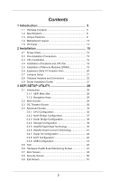
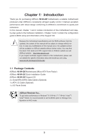
Package Contents 5 1.2 Specifications 6 1.3 Unique Features 9 1.4 Motherboard Layout 13 1.5 I/O Panel 14 2 Installation 15 2.1 Screw 20 2.7 Jumpers Setup 21 2.8 Onboard Headers and Connectors 22 2.9 Driver Installation Guide 27 3 UEFI SETUP UTILITY 28 3.1 Introduction 28 3.1.1 UEFI Menu - ASRock H61M-IDE | User Manual - Page 4
4 Software Support 52 4.1 Install Operating System 52 4.2 Support CD Information 52 4.2.1 Running Support CD 52 4.2.2 Drivers Menu 52 4.2.3 Utilities Menu 52 4.2.4 Contact Information 52 4 - ASRock H61M-IDE | User Manual - Page 5
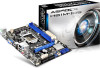
website for specific information about the model you are using. www.asrock.com/support/index.asp 1.1 Package Contents ASRock H61M-IDE Motherboard (Micro ATX Form Factor) ASRock H61M-IDE Quick Installation Guide ASRock H61M-IDE Support CD 2 x Serial ATA (SATA) Data Cables (Optional) 1 x ATA 133 Cable - ASRock H61M-IDE | User Manual - Page 6
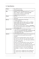
2nd Generation Intel® CoreTM i7 / i5 / i3 / Xeon® / Pentium® / Celeron® in LGA1155 package - Supports Intel® Turbo Boost 2.0 Technology - Supports K-Series unlocked CPU - Intel® H61 - Supports Intel® Rapid Start Technology and Smart Connect Technology - Dual Channel DDR3 Memory Technology - 2 x DDR3 - ASRock H61M-IDE | User Manual - Page 7
3.0 Gb/s Connectors, support NCQ, AHCI and Hot Plug - 1 x ATA133 IDE Connector (Supports 2 x IDE devices) - 1 x Support 4 USB 2.0 ports) - 32Mb AMI UEFI Legal BIOS with GUI support - Supports "Plug and Play" - ACPI 1.1 Compliant wake up events - Supports jumperfree - SMBIOS 2.3.1 support - Drivers - ASRock H61M-IDE | User Manual - Page 8
involved with overclocking, including adjusting the setting in the BIOS, applying Untied Overclocking Technology, or using third-party For Windows® OS with 64bit CPU, there is no such limitation. You can use ASRock XFast RAM to utilize the memory that Windows® cannot use. 2. Realtek RealWoW! - ASRock H61M-IDE | User Manual - Page 9
®. With this utility, you can press the key during the POST or the key to enter into the BIOS setup menu to access ASRock Instant Flash. Just launch this tool and save the new BIOS file to your USB flash drive, floppy disk or hard drive, then you can update your - ASRock H61M-IDE | User Manual - Page 10
APP Charger. Simply install the APP Charger driver, it makes your iPhone charge much quickly from your computer and up to 40% faster than before. ASRock APP Charger allows you to quickly charge many Apple devices simultaneously and even supports continuous charging when your PC enters into Standby - ASRock H61M-IDE | User Manual - Page 11
loss occurs during the BIOS update process, ASRock Crashless BIOS will automatically finish the BIOS update procedure after regaining power. Please note that BIOS files need to be placed in the root directory of your USB disk. Only USB2.0 ports support this feature. ASRock OMG (Online Management - ASRock H61M-IDE | User Manual - Page 12
LGA 1155 and LGA 1156. Please be noticed that not all the 775 and 1156 CPU Fan can be used. ASRock Good Night LED ASRock Good Night LED technology can offer you a better environment by extinguishing the unessential LED. By enabling Good Night LED in BIOS, the - ASRock H61M-IDE | User Manual - Page 13
LAN H61M-IDE PCIE1 XFast RAM CHA_FAN1 Top: LINE IN Center: FRONT Bottom: MIC IN AUDIO CODEC Super I/O CMOS BATTERY HD_AUDIO1 CI1 1 1 1 SPDIF_OUT1 IR1 TPM1 1 1 IDE1 PCIE2 USB4_5 1 USB6_7 1 CLRCMOS1 1 PLED1 1 PLED PWRBTN 1 HDLED RESET PANEL1 Intel H61 SATA_3 SATA_1 32Mb BIOS - ASRock H61M-IDE | User Manual - Page 14
1.5 I/O Panel 1 2 3 4 5 9 8 7 6 1 PS/2 Mouse Port (Green) 6 USB 2.0 Ports (USB23) 2 LAN RJ-45 Port* 7 USB 2.0 Ports (USB01) 3 Line In (Light Blue) 8 D-Sub Port (VGA1) 4 Front Speaker (Lime) 9 PS/2 Keyboard Port (Purple) 5 Microphone (Pink) * There are two LED next to the LAN - ASRock H61M-IDE | User Manual - Page 15
settings. 1. Unplug the power cord from the wall socket before touching any component. 2. To avoid damaging the motherboard components due to static electricity, NEVER place your motherboard directly on the carpet or the like. Also remember to use a grounded wrist strap or touch a safety grounded - ASRock H61M-IDE | User Manual - Page 16
follow the steps below. Load Plate Load Lever Contact Array Socket Body 1155-Pin Socket Overview Before you insert the 1155-Pin CPU into the socket, please check if the CPU surface is kicking off the PnP cap. 2. This cap must be placed if returning the motherboard for after service. 16 - ASRock H61M-IDE | User Manual - Page 17
key notch alignment key Pin1 Pin1 orientation key notch 1155-Pin CPU alignment key 1155-Pin Socket For proper inserting, please ensure to match retention tab of load lever. Please be noticed that this motherboard supports Combo Cooler Option (C.C.O.), which provides the flexible option to adopt - ASRock H61M-IDE | User Manual - Page 18
of CPU Fan and Heatsink This motherboard is equipped with 1155-Pin socket that supports Intel 1155-Pin CPU. Please adopt the please kindly refer to the instruction manuals of your CPU fan and heatsink. Below is an example to illustrate the installation of the heatsink for 1155-Pin CPU. Step 1. Apply - ASRock H61M-IDE | User Manual - Page 19
2.5 Installation of Memory Modules (DIMM) This motherboard provides two 240-pin DDR3 (Double Data Rate 3) DIMM slots, and supports Dual Channel Memory Technology. For dual channel configuration, you always need to install two identical (the same brand, speed, size and chiptype) memory modules in - ASRock H61M-IDE | User Manual - Page 20
Express Slots) There are 2 PCI Express slots on this motherboard. PCIE slots: PCIE1 (PCIE 3.0 x16 slot) is used for PCI Express x16 lane width graphics cards. PCIE2 (PCIE 2.0 x1 slot) is used for PCI Express x1 lane width cards. Only PCIE1 slot supports Gen 3 speed. To run the PCI Express in - ASRock H61M-IDE | User Manual - Page 21
and pin3 on CLRCMOS1 for 5 seconds. However, please do not clear the CMOS right after you update the BIOS. If you need to clear the CMOS when you just finish updating the BIOS, you must boot up the system first, and then shut it down before you do the clear-CMOS action - ASRock H61M-IDE | User Manual - Page 22
connected to the SATA / SATA2 hard disk or the SATA2 connector on this motherboard. Besides four default USB 2.0 ports on the I/O panel, there are two USB 2.0 headers on this motherboard. Each USB 2.0 header can support two USB 2.0 ports. Infrared Module Header (5-pin IR1) (see p.13 No. 16 - ASRock H61M-IDE | User Manual - Page 23
allows convenient connection and control of audio devices. 1. High Definition Audio supports Jack Sensing, but the panel wire on the chassis must support HDA to function correctly. Please follow the instruction in our manual and chassis manual to install your system. 2. If you use AC'97 audio - ASRock H61M-IDE | User Manual - Page 24
FAN_SPEED_CONTROL Please connect the CPU fan cable to the connector and match the black wire to the ground pin. Though this motherboard provides 4-Pin CPU fan (Quiet Fan) support, the 3-Pin CPU fan still can work successfully even without the fan speed control function. If you plan to connect - ASRock H61M-IDE | User Manual - Page 25
pin CI1) (see p.13, No. 19) 1 GND Signal SPDIF Out Connector (2-pin SPDIF_OUT1) (see p.13, No. 18) 1 GND SPDIFOUT This motherboard supports CASE OPEN detection feature that detects if the chassis cover has been removed. This feature requires a chassis with chassis intrusion - ASRock H61M-IDE | User Manual - Page 26
Primary IDE Connector (39-pin IDE1, see p.13 No. 15) connect the blue end to the motherboard connect the black end to the IDE devices 80-conductor ATA 66/100/133 cable Note: Please refer to the instruction of your IDE device vendor for the details. 26 - ASRock H61M-IDE | User Manual - Page 27
2.9 Driver Installation Guide To install the drivers to your system, please insert the support CD to your optical drive first. Then, the drivers compatible to your system can be auto-detected and listed on the support CD driver page. Please follow the order from up to bottom side to install those - ASRock H61M-IDE | User Manual - Page 28
Chapter 3: UEFI SETUP UTILITY 3.1 Introduction This section explains how to use the UEFI SETUP UTILITY to configure your system. The UEFI chip on the motherboard stores the UEFI SETUP UTILITY. You may run the UEFI SETUP UTILITY when you start up the computer. Please press or during the - ASRock H61M-IDE | User Manual - Page 29
3.1.2 Navigation Keys Please check the following table for the function description of each navigation key. Navigation Key(s) Function Description / Moves cursor left or right to select Screens / Moves cursor up or down to select items + / - To change option for the selected items - ASRock H61M-IDE | User Manual - Page 30
Use this item to change the ratio value of this motherboard. Intel SpeedStep Technology Intel SpeedStep technology is Intel's new power [Enabled]. This item will be hidden if the current CPU does not support Intel SpeedStep technology. Please note that enabling this function may reduce CPU voltage - ASRock H61M-IDE | User Manual - Page 31
[Auto]. GT OverClocking Support Use this item to enable or disable GT OverClocking Support. The default value is motherboard will detect the memory module(s) inserted and assign the appropriate frequency automatically. DRAM Configuration DRAM tCL Use this item to change CAS# Latency (tCL) Auto/Manual - ASRock H61M-IDE | User Manual - Page 32
setting. The default is [Auto]. DRAM tRTP Use this item to change Read to Precharge (tRTP) Auto/Manual setting. The default is [Auto]. DRAM tFAW Use this item to change Four Activate Window (tFAW) Auto/Manual setting. The default is [Auto]. DRAM tCWL Use this item to change CAS# Write Latency (tCWL - ASRock H61M-IDE | User Manual - Page 33
MRC Fast Boot Use this item to enable or disable MRC Fast Boot. The default is [Enabled]. Voltage Configuration DRAM Voltage Use this to select DRAM Voltage. The default value is [Auto]. 33 - ASRock H61M-IDE | User Manual - Page 34
3.4 Advanced Screen In this section, you may set the configurations for the following items: CPU Configuration, North Bridge Configuration, South Bridge Configuration, Storage Configuration, Intel(R) Rapid Start Technology, Intel(R) Smart Connect Technology, Super IO Configuration, ACPI - ASRock H61M-IDE | User Manual - Page 35
package. The default value is [All]. Enhance Halt State (C1E) All processors support the Halt State (C1). The C1 state is supported through the native processor instructions HLT and MWAIT and requires no hardware support from the chipset. In the C1 power state, the processor maintains the context - ASRock H61M-IDE | User Manual - Page 36
prevent data pages from being used by malicious software to execute codes. This option will be hidden if the current CPU does not support No-Excute Memory Protection. Intel Virtualization Technology When this option is set to [Enabled], a VMM (Virtual Machine Architecture) can utilize the additional - ASRock H61M-IDE | User Manual - Page 37
3.4.2 North Bridge Configuration Primary Graphics Adapter This allows you to select [Onboard] or [PCI Express] as the boot graphic adapter priority. The default value is [PCI Express]. VT-d Use this to enable or disable Intel® VT-d technology (Intel® Virtualization Technology for Directed - ASRock H61M-IDE | User Manual - Page 38
3.4.3 South Bridge Configuration Onboard HD Audio Select [Auto], [Enabled] or [Disabled] for the onboard HD Audio feature. If you select [Auto], the onboard HD Audio will be disabled when PCI Sound Card is plugged. Front Panel Select [Auto] or [Disabled] for the onboard HD Audio Front Panel. Onboard - ASRock H61M-IDE | User Manual - Page 39
], [AHCI Mode] and [Disabled]. The default value is [AHCI Mode]. AHCI (Advanced Host Controller Interface) supports NCQ and other new features that will improve SATA disk performance but IDE mode does not have these advantages. SATA Aggressive Link Power Management Use this item to configure SATA - ASRock H61M-IDE | User Manual - Page 40
5-6 seconds. The default is [Enabled]. Entry After Select a time to enable RTC wake timer at S3 entry. The default is [10 minutes]. Active Page Threshold Support This allows you to enable or disable Active Page Threshold - ASRock H61M-IDE | User Manual - Page 41
3.4.6 Intel(R) Smart Connect Technology Intel(R) Smart Connect Technology Use this item to enable or disable Intel(R) Smart Connect Technology. Intel(R) Smart Connect Technology keeps your e-mail and social networks, such as Twitter, Facebook, etc. updated automatically while the computer is in - ASRock H61M-IDE | User Manual - Page 42
3.4.7 Super IO Configuration Infrared Port Use this item to enable or disable the onboard infrared port. 42 - ASRock H61M-IDE | User Manual - Page 43
-toRAM feature. Selecting [Auto] will enable this feature if the OS supports it. Check Ready Bit Use this item to enable or disable the feature ]. Please set this option to [Enabled] if you plan to use this motherboard to submit Windows® certification. PS/2 Keyboard Power On Use this item to enable - ASRock H61M-IDE | User Manual - Page 44
]. The default value is [Enabled]. Please refer to below descriptions for the details of these four options: [Enabled] - Enables support for legacy USB. [Auto] - Enables legacy support if USB devices are connected. [Disabled] - USB devices are not allowed to use under legacy OS and UEFI setup when - ASRock H61M-IDE | User Manual - Page 45
3.5 Tool OMG(Online Management Guard) Administrators are able to establish an internet curfew or restrict internet access at specified times via OMG. You may schedule the starting and ending hours of internet access granted to other users. In order to prevent users from bypassing OMG, guest accounts - ASRock H61M-IDE | User Manual - Page 46
firmware download server for Internet Flash. Configuration options: [Asia], [Europe], [USA] and [China]. Dehumidifier Function Users may prevent motherboard damages due to dampness by enabling "Dehumidifier Function". When enabling Dehumidifier Function, the computer will power on automatically to - ASRock H61M-IDE | User Manual - Page 47
Screen In this section, it allows you to monitor the status of the hardware on your system, including the parameters of the CPU temperature, motherboard temperature, CPU fan speed, chassis fan speed, and the critical voltage. CPU Fan Setting This allows you to set the CPU fan speed. Configuration - ASRock H61M-IDE | User Manual - Page 48
not boot by using an USB flash drive. [Ultra Fast] - There are a few restrictions. 1. Only supports Windows® 8 UEFI operating system. 2. You will not be able to enter BIOS Setup (Clear CMOS or run utility in Widows® to enter BIOS Setup). 3. If you are using an external graphics card, the VBIOS must - ASRock H61M-IDE | User Manual - Page 49
Full Screen Logo Use this item to enable or disable OEM Logo. The default value is [Enabled]. AddOn ROM Display Use this option to adjust AddOn ROM Display. If you enable the option "Full Screen Logo" but you want to see the AddOn ROM information when the system boots, please select [Enabled]. - ASRock H61M-IDE | User Manual - Page 50
3.8 Security Screen In this section, you may set or change the supervisor/user password for the system. For the user password, you may also clear it. Secure Boot Use this to enable or disable Secure Boot. The default value is [Disabled]. 50 - ASRock H61M-IDE | User Manual - Page 51
3.9 Exit Screen Save Changes and Exit When you select this option, the following message "Save configuration changes and exit setup?" will pop-out. Select [Yes] to save the changes and exit the UEFI SETUP UTILITY. Discard Changes and Exit When you select this option, the following message "Discard - ASRock H61M-IDE | User Manual - Page 52
install the necessary drivers to activate the devices. 4.2.3 Utilities Menu The Utilities Menu shows the applications software that the motherboard supports. Click on a specific item then follow the installation wizard to install it. 4.2.4 Contact Information If you need to contact ASRock or want to - ASRock H61M-IDE | User Manual - Page 53
Installing OS on a HDD Larger Than 2TB This motherboard is adopting UEFI BIOS that allows Windows® OS to be installed on a large install Windows® 7 64-bit OS, OS will be formatted by GPT (GUID Partition Table). Please install the hotfix file from Microsoft®: http://support.microsoft.com/kb/979903 53
-
 1
1 -
 2
2 -
 3
3 -
 4
4 -
 5
5 -
 6
6 -
 7
7 -
8
-
9
-
10
-
11
-
12
-
13
-
14
-
15
-
16
-
17
-
18
-
19
-
20
-
21
-
22
-
23
-
24
-
25
-
26
-
27
-
28
-
29
-
30
-
31
-
32
-
33
-
34
-
35
-
36
-
37
-
38
-
39
-
40
-
41
-
42
-
43
-
44
-
45
-
46
-
47
-
48
-
49
-
50
-
51
-
52
-
53
 |
 |

1
H61M-IDE
User Manual
Version 1.1
Published November 2013
Copyright©2013 ASRock INC. All rights reserved.