ASRock J4025B-ITX User Manual
ASRock J4025B-ITX Manual
 |
View all ASRock J4025B-ITX manuals
Add to My Manuals
Save this manual to your list of manuals |
ASRock J4025B-ITX manual content summary:
- ASRock J4025B-ITX | User Manual - Page 1
- ASRock J4025B-ITX | User Manual - Page 2
Version 1.0 Published December 2019 Copyright©2019 ASRock INC. All rights reserved. Copyright Notice: No part of this documentation may be reproduced, transcribed, transmitted, or translated in any language, in any form or by any means, except duplication of documentation by the purchaser for backup - ASRock J4025B-ITX | User Manual - Page 3
AUSTRALIA ONLY Our goods come with guarantees that cannot be excluded under the Australian Consumer Law. You are entitled to a replacement or refund for a major failure and compensation for any other reasonably foreseeable loss or damage caused by our goods. You are also entitled to have the goods - ASRock J4025B-ITX | User Manual - Page 4
Contents Chapter 1 Introduction 1 1.1 Package Contents 1 1.2 Specifications 2 1.3 Motherboard Layout 5 1.4 I/O Panel 7 Chapter 2 Installation 9 2.1 Installing Memory Modules (SO-DIMM) 10 2.2 Expansion Slot (PCI Express Slot) 12 2.3 Jumpers Setup 13 2.4 Onboard Headers and - ASRock J4025B-ITX | User Manual - Page 5
4.3 Advanced Screen 28 4.3.1 CPU Configuration 29 4.3.2 Chipset Configuration 30 4.3.3 Storage Configuration 32 4.3.4 Super IO Configuration 33 4.3.5 ACPI Configuration 35 4.3.6 USB Configuration 37 4.4 Tools 38 4.5 Hardware Health Event Monitoring Screen 40 4.6 Security Screen 41 - ASRock J4025B-ITX | User Manual - Page 6
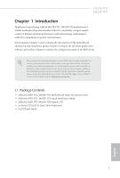
manual, Chapter 1 and 2 contains the introduction of the motherboard and step-by-step installation guides. Chapter 3 contains the operation guide the model you are using. You may find the latest VGA cards and CPU support list on ASRock's website as well. ASRock website http://www.asrock.com. 1.1 - ASRock J4025B-ITX | User Manual - Page 7
(up to 2.9 GHz) (for J4025B-ITX) Memory • Dual Channel DDR4 Memory Technology • 2 x DDR4 SO-DIMM Slots * 2GB DRAM per module is not supported. • Supports DDR4 2400/2133 non-ECC, un-buffered memory • Max. capacity of system memory: 8GB Expansion Slot • 1 x PCI Express 2.0 x16 Slot (PCIE1: x2 - ASRock J4025B-ITX | User Manual - Page 8
Port with LED (ACT/LINK LED and SPEED LED) • HD Audio Jacks: Line in / Front Speaker / Microphone Storage • 2 x SATA3 6.0 Gb/s Connectors, support NCQ, AHCI and Hot Plug Connector • 1 x COM Port Header • 1 x Chassis Intrusion and Speaker Header • 1 x CPU Fan Connector (3-pin) • 1 x Chassis Fan - ASRock J4025B-ITX | User Manual - Page 9
CPU/Chassis Fan multi-speed control • CASE OPEN detection • Voltage monitoring: +12V, +5V, +3.3V, CPU Vcore OS • Microsoft® Windows® 10 64-bit * Supports UEFI mode only Certifications • FCC, CE • ErP/EuP ready (ErP/EuP ready power supply is required) * For detailed product information, please - ASRock J4025B-ITX | User Manual - Page 10
1.3 Motherboard Layout J4125B-ITX J4025B-ITX 1 CPU_FAN1 PS2 Keyboard/ Mouse USB 3.2 Gen1 T: USB1 B: USB2 RoHS COM1 VGA1 AT X P W R 1 DDR4_A1 PARALLEL PORT BIOS ROM 2 CMOS Battery LAN PANEL1 PLED PWRBTN HDLED RESET HDMI1 3 1 SPK_CI1 DDR4_B1 4 HD_AUDIO1 1 AUDIO CODEC 1 CLRMOS1 5 - ASRock J4025B-ITX | User Manual - Page 11
No. Description 1 CPU Fan Connector (CPU_FAN1) 2 ATX Power Connector (ATXPWR1) 3 System Panel Header (PANEL1) 4 Chassis Intrusion and Speaker Header (SPK_CI1) 5 Clear CMOS Jumper (CLRMOS1) 6 Chassis Fan Connector (CHA_FAN1) 7 2 x 260-pin DDR4 SO-DIMM Slots (DDR4_A1, DDR4_B1) 8 COM Port Header (COM2) - ASRock J4025B-ITX | User Manual - Page 12
1.4 I/O Panel 1 2 J4125B-ITX J4025B-ITX 4 3 5 12 11 No. Description 1 PS/2 Mouse/Keyboard Port 2 Parallel Port 3 LAN RJ-45 Port* 4 Line In (Light Blue)** 5 Front Speaker (Lime)** 6 Microphone (Pink)** 10 9 7 6 8 No. Description 7 USB 2.0 Port (USB3_3) 8 USB 3.2 Gen1 Port (USB3_4) 9 - ASRock J4025B-ITX | User Manual - Page 13
** To configure 7.1 CH HD Audio, it is required to use an HD front panel audio module and enable the multichannel audio feature through the audio driver. Please set Speaker Configuration to "7.1 Speaker"in the Realtek HD Audio Manager. Function of the Audio Ports in 7.1-channel Configuration: Port - ASRock J4025B-ITX | User Manual - Page 14
J4125B-ITX J4025B-ITX Chapter 2 Installation This is a Mini-ITX form factor motherboard. Before you install the motherboard, study the configuration of your chassis to ensure that the motherboard fits into it. Pre-installation Precautions Take note of the following precautions before you install - ASRock J4025B-ITX | User Manual - Page 15
orientation. It will cause permanent damage to the motherboard and the SO-DIMM if you force the SO-DIMM into the slot at incorrect orientation. Supported DDR4 Non ECC SODIMM Raw Card A (1Rx8) B (2Rx8) C (1Rx16) Dual Channel Memory Configuration DDR4_A1 DDR4_B1 Populated Populated English 10 - ASRock J4025B-ITX | User Manual - Page 16
J4125B-ITX J4025B-ITX 1 2 3 11 English - ASRock J4025B-ITX | User Manual - Page 17
2.2 Expansion Slot (PCI Express Slot) There is 1 PCI Express slot on the motherboard. Before installing an expansion card, please make sure that the power supply is switched off or the power cord is unplugged. Please read the documentation of the expansion card and make necessary hardware settings - ASRock J4025B-ITX | User Manual - Page 18
J4125B-ITX J4025B-ITX 2.3 Jumpers Setup The illustration shows how jumpers are setup. When the jumper cap is placed on the pins, the jumper is "Short". If no jumper cap is placed on the pins, the jumper is "Open". *The jumper cap is not provided. Clear CMOS Jumper (CLRMOS1) (see p.5, No. 5) 2-pin - ASRock J4025B-ITX | User Manual - Page 19
2.4 Onboard Headers and Connectors Onboard headers and connectors are NOT jumpers. Do NOT place jumper caps over these headers and connectors. Placing jumper caps over the headers and connectors will cause permanent damage to the motherboard. System Panel Header (9-pin PANEL1) (see p.5, No. 3) GND - ASRock J4025B-ITX | User Manual - Page 20
J4125B-ITX J4025B-ITX Serial ATA3 Connectors (SATA3_1: see p.5, No. 12) (SATA3_2: see p.5, No. 13) SATA3_2 SATA3_1 These two SATA3 connectors support SATA data cables for internal storage devices with up to 6.0 Gb/s data transfer rate. USB 2.0 Headers (9-pin USB2_3) (see p.5, No. 11) (9-pin - ASRock J4025B-ITX | User Manual - Page 21
Jack Sensing, but the panel wire on the chassis must support HDA to function correctly. Please follow the instructions in our manual and chassis manual to install your system. 2. If you use an AC'97 audio panel, please install it to the front panel audio header by the steps below: A. - ASRock J4025B-ITX | User Manual - Page 22
Serial Port Header (9-pin COM2) (see p.5, No. 8) J4125B-ITX J4025B-ITX RRXD1 DDTR#1 DDSR#1 CCTS#1 1 RRI#1 RRTS#1 GND TTXD1 DDCD#1 This COM2 header supports a serial port module. English 17 - ASRock J4025B-ITX | User Manual - Page 23
CD that comes with the motherboard contains necessary drivers and useful utilities that enhance the motherboard's features. Running The Support CD To begin using the support CD, insert the CD into your CD-ROM drive. The CD automatically displays the Main Menu if "AUTORUN" is enabled in your computer - ASRock J4025B-ITX | User Manual - Page 24
Shop is an online store for purchasing and downloading software applications for your ASRock computer. You can quickly and easily install various apps and support utilities. With ASRock Live Update & APP Shop, you can optimize your system and keep your motherboard up to date simply with a few clicks - ASRock J4025B-ITX | User Manual - Page 25
3.2.2 Apps When the "Apps" tab is selected, you will see all the available apps on screen for you to download. Installing an App Step 1 Find the app you want to install. The most recommended app appears on the left side of the screen. The other various apps are shown on the right. Please scroll up - ASRock J4025B-ITX | User Manual - Page 26
Step 3 If you want to install the app, click on the red icon J4125B-ITX J4025B-ITX to start downloading. Step 4 When installation completes, you can find the green "Installed" icon appears on the upper right corner. English To uninstall it, simply click on the trash can icon . *The trash icon - ASRock J4025B-ITX | User Manual - Page 27
Upgrading an App You can only upgrade the apps you have already installed. When there is an available new version for your app, you will find the mark of "New Version" appears below the installed app icon. Step 1 Click on the app icon to see more details. Step 2 Click on the yellow icon to start - ASRock J4025B-ITX | User Manual - Page 28
J4125B-ITX J4025B-ITX 3.2.3 BIOS & Drivers Installing BIOS or Drivers When the "BIOS & Drivers" tab is selected, you will see a list of recommended or critical updates for the BIOS or drivers. Please update them all soon. Step 1 Please check the item information before update. Click on Step 2 to - ASRock J4025B-ITX | User Manual - Page 29
3.2.4 Setting In the "Setting" page, you can change the language, select the server location, and determine if you want to automatically run the ASRock Live Update & APP Shop on Windows startup. 24 English - ASRock J4025B-ITX | User Manual - Page 30
J4125B-ITX J4025B-ITX Chapter 4 UEFI SETUP UTILITY 4.1 Introduction This section explains how to use the UEFI SETUP UTILITY to configure your system. You may run the UEFI SETUP UTILITY by pressing or right after you power on the computer, otherwise, the Power-On-Self-Test (POST) will - ASRock J4025B-ITX | User Manual - Page 31
4.1.2 Navigation Keys Use < > key or < > key to choose among the selections on the menu bar, and use < > key or < > key to move the cursor up or down to select items, then press to get into the sub screen. You can also use the mouse to click your required item. Please check the following - ASRock J4025B-ITX | User Manual - Page 32
J4125B-ITX J4025B-ITX 4.2 Main Screen When you enter the UEFI SETUP UTILITY, the Main screen will appear and display the system overview. J4125B-ITX: J4025B-ITX: 27 English - ASRock J4025B-ITX | User Manual - Page 33
4.3 Advanced Screen In this section, you may set the configurations for the following items: CPU Configuration, Chipset Configuration, Storage Configuration, Super IO Configuration, ACPI Configuration and USB Configuration. Setting wrong values in this section may cause the system to malfunction. 28 - ASRock J4025B-ITX | User Manual - Page 34
technology allows processors to switch between multiple frequencies and voltage points for better power saving and heat dissipation. CPU C States Support Enable CPU C States Support for power saving. It is recommended to keep C1 and C6 all enabled for better power saving. Enhanced Halt State - ASRock J4025B-ITX | User Manual - Page 35
4.3.2 Chipset Configuration DRAM Voltage Use this to configure DRAM Voltage. The default value is [Auto]. Primary Graphics Adapter Select a primary VGA. Share Memory Configure the size of memory that is allocated to the integrated graphics processor when the system boots up. Onboard HD Audio Enable/ - ASRock J4025B-ITX | User Manual - Page 36
J4125B-ITX J4025B-ITX ASPM This option enables/disables the ASPM support. Deep Sleep Configure deep sleep mode for power saving when the computer is shut down. Restore on AC/Power Loss Select the power state after a - ASRock J4025B-ITX | User Manual - Page 37
Link Power Management allows SATA devices to enter a low power state during periods of inactivity to save power. It is only supported by AHCI mode. Hard Disk S.M.A.R.T. S.M.A.R.T stands for Self-Monitoring, Analysis, and Reporting Technology. It is a monitoring system for computer hard disk - ASRock J4025B-ITX | User Manual - Page 38
4.3.4 Super IO Configuration J4125B-ITX J4025B-ITX Serial Port 1 Enable or disable the Serial port 1. Serial Port Address Select the address of the Serial port. Serial Port 2 Enable or disable the Serial port 2. Serial Port Address Select the address of the Serial port. Parallel Port Enable or - ASRock J4025B-ITX | User Manual - Page 39
PS2 Y-Cable Enable the PS2 Y-Cable or set this option to Auto. 34 English - ASRock J4025B-ITX | User Manual - Page 40
4.3.5 ACPI Configuration J4125B-ITX J4025B-ITX Suspend to RAM It is recommended to select auto for ACPI S3 power saving. ACPI HPET Table Enable the High Precision Event Timer for better performance and to pass WHQL tests. PS/2 Keyboard Power On Allow the system to be waked up by a PS/2 Keyboard. - ASRock J4025B-ITX | User Manual - Page 41
USB Keyboard/Remote Power On Allow the system to be waked up by an USB keyboard or remote controller. USB Mouse Power On Allow the system to be waked up by an USB mouse. 36 English - ASRock J4025B-ITX | User Manual - Page 42
4.3.6 USB Configuration J4125B-ITX J4025B-ITX Legacy USB Support Enable Legacy USB Support. AUTO option disables legacy support if no USB devices are connected. DISABLE option will keep USB devices available only for EFI applications. English 37 - ASRock J4025B-ITX | User Manual - Page 43
4.4 Tools Instant Flash Save UEFI files in your USB storage device and run Instant Flash to update your UEFI. Internet Flash ASRock Internet Flash downloads and updates the latest UEFI firmware version from our servers for you. Please setup network configuration before using Internet Flash. *For - ASRock J4025B-ITX | User Manual - Page 44
Network Configuration Use this to configure internet connection settings for Internet Flash. J4125B-ITX J4025B-ITX Internet Setting Enable or disable sound effects in the setup utility. UEFI Download Server Select a server to download the UEFI firmware. 39 English - ASRock J4025B-ITX | User Manual - Page 45
default value is [Full On]. Chassis Fan 1 Setting This allows you to set chassis fan 1's speed. Configuration options: [Full On], [Automatic Mode] and [Manual]. The default value is [Full On]. Case Open Feature Enable or disable Case Open Feature to detect whether the chassis cover has been removed - ASRock J4025B-ITX | User Manual - Page 46
are unable to change the settings in the UEFI Setup Utility. Leave it blank and press enter to remove the password. Secure Boot Enable to support Secure Boot. Intel(R) Platform Trust Technology Enable/disable Intel PTT in ME. Disable this option to use discrete TPM Module. 41 English - ASRock J4025B-ITX | User Manual - Page 47
priority. Fast Boot Fast Boot minimizes your computer's boot time. In fast mode you may not boot from an USB storage device. The VBIOS must support UEFI GOP if you are using an external graphics card. Please notice that Ultra Fast mode will boot so fast that the only way to - ASRock J4025B-ITX | User Manual - Page 48
J4125B-ITX J4025B-ITX Full Screen Logo Enable to display the boot logo or disable to show normal POST messages. Boot Failure Guard Message If the computer fails to boot for a number of times the system automatically restores the default settings. 43 English - ASRock J4025B-ITX | User Manual - Page 49
4.8 Exit Screen Save Changes and Exit When you select this option the following message, "Save configuration changes and exit setup?" will pop out. Select [OK] to save changes and exit the UEFI SETUP UTILITY. Discard Changes and Exit When you select this option the following message, "Discard - ASRock J4025B-ITX | User Manual - Page 50
to visit ASRock's website at http://www.asrock.com; or you may contact your dealer for further information. For technical questions, please submit a support request form at https://event.asrock.com/tsd.asp ASRock Incorporation 2F., No.37, Sec. 2, Jhongyang S. Rd., Beitou District, Taipei City 112 - ASRock J4025B-ITX | User Manual - Page 51
DECLARATION OF CONFORMITY Per FCC Part 2 Section 2.1077(a) Responsible Party Name: ASRock Incorporation Address: 13848 Magnolia Ave, Chino, CA91710 Phone/Fax No: +1-909-590-8308/+1-909-590-1026 hereby declares that the product Product Name : Motherboard Model Number : J4125B-ITX / J4025B-ITX - ASRock J4025B-ITX | User Manual - Page 52
EU Declaration of Conformity For the following equipment: Motherboard (Product Name) J4125B-ITX / J4025B-ITX / ASRock (Model Designation / Trade Name) ASRock Incorporation (Manufacturer Name) 2F., No.37, Sec. 2, Jhongyang S. Rd., Beitou District, Taipei City 112, Taiwan (R.O.C.) (Manufacturer
-
 1
1 -
 2
2 -
 3
3 -
 4
4 -
 5
5 -
 6
6 -
 7
7 -
8
-
9
-
10
-
11
-
12
-
13
-
14
-
15
-
16
-
17
-
18
-
19
-
20
-
21
-
22
-
23
-
24
-
25
-
26
-
27
-
28
-
29
-
30
-
31
-
32
-
33
-
34
-
35
-
36
-
37
-
38
-
39
-
40
-
41
-
42
-
43
-
44
-
45
-
46
-
47
-
48
-
49
-
50
-
51
-
52
 |
 |
