ASRock K10N7SLI User Manual
ASRock K10N7SLI Manual
 |
View all ASRock K10N7SLI manuals
Add to My Manuals
Save this manual to your list of manuals |
ASRock K10N7SLI manual content summary:
- ASRock K10N7SLI | User Manual - Page 1
K10N7SLI User Manual Version 1.0 Published November 2008 Copyright©2008 ASRock INC. All rights reserved. 1 - ASRock K10N7SLI | User Manual - Page 2
purchaser for backup purpose, without written consent of ASRock Inc. Products and corporate names appearing in this manual may or may not be registered trademarks or copyrights USA ONLY The Lithium battery adopted on this motherboard contains Perchlorate, a toxic substance controlled in Perchlorate - ASRock K10N7SLI | User Manual - Page 3
1.2 Specifications 6 1.3 Supported PCI Express VGA Card List for SLITM Mode 11 1.4 Motherboard Layout 12 1.5 I/O SATA / SATAII HDD Hot Plug Feature and Operation Guide ....... 39 2.14 Driver Installation Guide 41 2.15 Installing Windows® XP / XP 64 . BIOS SETUP UTILITY 46 3.1 Introduction 46 3 - ASRock K10N7SLI | User Manual - Page 4
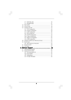
3.1.1 BIOS Menu Bar 46 3.1.2 Navigation Keys 47 3.2 Main Screen 47 3.3 Smart Screen 48 3.4 Advanced 64 3.8 Exit Screen 65 4 . Software Support 66 4.1 Install Operating System 66 4.2 Support CD Information 66 4.2.1 Running Support CD 66 4.2.2 Drivers Menu 66 4.2.3 Utilities Menu 66 4.2.4 - ASRock K10N7SLI | User Manual - Page 5
design conforming to ASRock's commitment to quality and endurance. In this manual, chapter 1 and 2 contain introduction of the motherboard and step-bystep guide to the hardware installation. Chapter 3 and 4 contain the configuration guide to BIOS setup and information of the Support CD. Because the - ASRock K10N7SLI | User Manual - Page 6
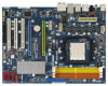
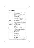
Panel I/O - ATX Form Factor: 12.0-in x 8.8-in, 30.5 cm x 22.4 cm - All Solid Capacitor design (100% Japan-made high-quality Conductive Polymer Capacitors) - Support for Socket AM2+ / AM2 processors: AMD PhenomTM FX / Phenom / Athlon 64 FX / Athlon 64 X2 Dual-Core / Athlon X2 Dual-Core / Athlon 64 - ASRock K10N7SLI | User Manual - Page 7
) - 8Mb AMI BIOS - AMI Legal BIOS - Supports "Plug and Play" - ACPI 1.1 Compliance Wake Up Events - Supports jumperfree - AMBIOS 2.3.1 Support - CPU, DRAM, Chipset Core, HTT Voltage Multi-adjustment - Supports Smart BIOS - Drivers, Utilities, AntiVirus Software (Trial Version) - ASRock OC Tuner (see - ASRock K10N7SLI | User Manual - Page 8
with overclocking, including adjusting the setting in the BIOS, applying Untied Overclocking Technology, or using the thirdparty This motherboard supports NVIDIA® SLITM technology. If you want to use SLITM function, please follow the instructions on page 20 to reverse the direction of ASRock SLI - ASRock K10N7SLI | User Manual - Page 9
SATAII connector, please read the "SATAII Hard Disk Setup Guide" on page 36 to adjust your SATAII hard disk drive to SATAII mode. You can also connect SATA hard disk to SATAII connector directly. 9. This motherboard supports eSATAII interface, the external SATAII specification. Please read "eSATAII - ASRock K10N7SLI | User Manual - Page 10
15. This motherboard supports ASRock AM2 Boost overclocking technology for AM2 CPU. If you enable this function in the BIOS setup, the memory performance will improve up to 12.5%, but the effect still depends on the AM2 CPU you adopt. Enabling this function will overclock - ASRock K10N7SLI | User Manual - Page 11
GeForce 7900GS GeForce 7300GS GeForce 7300GT * These two cards can only work under Windows® XP / XP 64-bit OS. For the latest updates of the supported PCI Express VGA card list for SLITM Mode, please visit our website for details. ASRock website: http://www.asrock.com/support/index.htm 11 - ASRock K10N7SLI | User Manual - Page 12
Motherboard /XFIRE_PWR1 IDE1 140W CPU FSB2.6GHz CPU_FAN1 PCIE1 LAN PHY PCIE2 K10N7SLI CMOS BATTERY Super I/O PCIE3 PCI Express 2.0 PCI1 AUDIO CODEC NVIDIA nForce 740a SLI Chipset 1 CLRCMOS1 RoHS FRONT_1394 1 8Mb BIOS CHA_FAN1 SPEAKER1 1 PANEL 1 PLED PWRBTN 1 HDLED RESET SATAII_2 - ASRock K10N7SLI | User Manual - Page 13
1 . 5 I/O Panel 1 2 3 4 7 5 8 6 9 16 15 14 13 12 11 10 1 PS/2 Mouse Port (Green) 2 IEEE 1394 Port * 3 LAN RJ-45 Port 4 Side Speaker (Gray) 5 Rear Speaker (Black) 6 Central / Bass (Orange) 7 Line In (Light Blue) **8 Front Speaker (Lime) 9 Microphone (Pink) 10 USB 2.0 Ports (USB01) 11 - ASRock K10N7SLI | User Manual - Page 14
the power is switched off or the power cord is detached from the power supply. Failure to do so may cause severe damage to the motherboard, peripherals, and/or components. 1. Unplug the power cord from the wall socket before touching any component. 2. To avoid damaging the - ASRock K10N7SLI | User Manual - Page 15
Socket Lever 2.2 Installation of CPU Fan and Heatsink After you install the CPU into this motherboard, it is necessary to install a larger heatsink and cooling fan to dissipate heat. You 4). For proper installation, please kindly refer to the instruction manuals of the CPU fan and the heatsink. 15 - ASRock K10N7SLI | User Manual - Page 16
2.3 Installation of Memory Modules (DIMM) This motherboard provides four 240-pin DDR2 (Double Data Rate 2) DIMM slots, and supports Dual Channel Memory Technology. For dual channel configuration, you always need to install identical (the same brand, speed, size and chip-type) DDR2 DIMM pair - ASRock K10N7SLI | User Manual - Page 17
matches the break on the slot. notch break notch break The DIMM only fits in one correct orientation. It will cause permanent damage to the motherboard and the DIMM if you force the DIMM into the slot at incorrect orientation. Step 3. Firmly insert the DIMM into the slot until the retaining - ASRock K10N7SLI | User Manual - Page 18
There are 3 PCI slots and 3 PCI Express slots on this motherboard. PCI Slots: PCI slots are used to install expansion cards that Express x16 lane width graphics cards, or used to install PCI Express graphics cards to support SLITM function. PCIE3 (PCIE x16 slot; Blue) is used for PCI Express x1 lane - ASRock K10N7SLI | User Manual - Page 19
motherboard, please install it on PCIE2 slot (Green). In this mode, you do not need to adjust the default setting of ASRock SLI/XFire Switch Card, and please do not remove or lose ASRock to the "Supported PCI Express VGA Card List for SLITM Mode" on page 11 and "SLITM Operation Guide" on page 20 - ASRock K10N7SLI | User Manual - Page 20
2.5 SLITM Operation Guide This motherboard supports NVIDIA® SLITM (Scalable Link Interface) technology that allows you to install two identical NVIDIA® SLITM enabled PCI Express x16 graphics cards. Currently, NVIDIA® SLITM technology supports Windows® XP, XP 64-bit, VistaTM and VistaTM 64-bit OS. - ASRock K10N7SLI | User Manual - Page 21
Step 3. Reverse the card direction so as to have the "X8 / X8 MODE" wording side toward the retention slot base. Insert the card into the bottom of the base. Step 4. Push the card down into the retention slot till both the retention arms firmly hold the card into position. Also, keep away from - ASRock K10N7SLI | User Manual - Page 22
graphics card that is inserted to PCIE2 slot. Connect a 4-pin ATX power cable to SLI/XFIRE power connector. Step 10. Install the graphics card drivers to your system. After that, you can enable the Multi-Graphics Processing Unit (GPU) feature in the NVIDIA® nView system tray utility. Please follow - ASRock K10N7SLI | User Manual - Page 23
E. From the Display Properties dialog box, select the Settings tab then click Advanced. F. Select the NVIDIA GeForce tab. G. Click the slider to display the following screen, then select the SLI multi-GPU item. H. Click the Enable SLI multi-GPU check box. I. Click OK when done. 23 - ASRock K10N7SLI | User Manual - Page 24
For Windows® VistaTM / VistaTM 64-bit OS: A. Click the Start icon on your Windows taskbar. B. From the pop-up menu, select All Programs, and then click NVIDIA Corporation. C. Select NVIDIA Control Panel tab. D. Select Control Panel tab. E. From the pop-up menu, select Set SLI configuration, and then - ASRock K10N7SLI | User Manual - Page 25
and pin3 on CLRCMOS1 for 5 seconds. However, please do not clear the CMOS right after you update the BIOS. If you need to clear the CMOS when you just finish updating the BIOS, you must boot up the system first, and then shut it down before you do the clear-CMOS action - ASRock K10N7SLI | User Manual - Page 26
to the motherboard IDE1 connect the black end to the IDE devices 80-conductor ATA 66/100/133 cable Note: Please refer to the instruction of your ) SATAII_5 (PORT4) These six Serial ATAII (SATAII) connectors support SATA data cables for internal storage devices. The current SATAII interface - ASRock K10N7SLI | User Manual - Page 27
power cable to the power connector of the power supply. Besides six default USB 2.0 ports on the I/O panel, there are two USB 2.0 headers on this motherboard. Each USB 2.0 header can support two USB 2.0 ports. This header supports an optional wireless transmitting and receiving infrared module. 27 - ASRock K10N7SLI | User Manual - Page 28
supports Jack Sensing, but the panel wire on the chassis must support HDA to function correctly. Please follow the instruction in our manual and chassis manual need to connect them for AC'97 audio panel. E. Enter BIOS Setup Utility. Enter Advanced Settings, and then select Chipset Configuration. - ASRock K10N7SLI | User Manual - Page 29
2 GND 1 Please connect the CPU fan cable to this connector and match the black wire to the ground pin. Though this motherboard provides 4-Pin CPU fan (Quiet Fan) support, the 3-Pin CPU fan still can work successfully even without the fan speed control function. If you plan to connect the 3-Pin - ASRock K10N7SLI | User Manual - Page 30
12V RXTPBP_0 GND RXTPAP_0 Besides one default IEEE 1394 port on the I/O panel, there is one IEEE 1394 header (FRONT_1394) on this motherboard. This IEEE 1394 header can support one IEEE 1394 port. Serial port Header (9-pin COM1) (see p.12 No.36) RRXD1 DDTR#1 DDSR#1 CCTS#1 1 RRI#1 RRTS#1 GND TTXD1 - ASRock K10N7SLI | User Manual - Page 31
HDMI_SPDIF Cable (Optional) C B A Please connect the black end (A) of HDMI_SPDIF cable to the HDMI_SPDIF header on the motherboard. Then connect the white end (B or C) of HDMI_SPDIF cable to the HDMI_SPDIF connector of HDMI VGA card. A. black end +5V SPDIFOUT GND blue black B. white - ASRock K10N7SLI | User Manual - Page 32
motherboard with a HDMI_SPDIF header. This motherboard motherboard. For the proper installation of HDMI VGA card, please refer to the installation guide manual of HDMI VGA card vendor. Incorrect connection may cause permanent damage to this motherboard Otherwise, the motherboard and the user manual for - ASRock K10N7SLI | User Manual - Page 33
Interface Introduction What is eSATAII? This motherboard supports eSATAII interface, the external SATAII specification. condition. 2. If you set "SATA Operation Mode" option in BIOS setup to IDE mode, Hot Plug function is not supported with eSATAII devices. If you still want to use eSATAII function - ASRock K10N7SLI | User Manual - Page 34
How to install eSATAII? eSATAII_TOP SATAII_6 (PORT5) 1. In order to enable the eSATAII port of the I/O shield, you need to connect the orange SATAII connector (SATAII_6 (PORT5); see p.12 No.12) and the eSATAII connector (eSATAII_TOP; see p.12 No.37) with a SATA data cable first. Connect the SATA - ASRock K10N7SLI | User Manual - Page 35
Comparison between eSATAII and other devices IEEE 1394 USB 2.0 SATA eSATAII/SATAII 400Mb/s 480Mb/s 1.5Gb/s (1500Mb/s) 3.0Gb/s (3000Mb/s) 35 - ASRock K10N7SLI | User Manual - Page 36
guide. Some default setting of SATAII hard disks may not be at SATAII mode, which operate with the best performance. In order to enable SATAII function, please follow the below instruction 's website for details: http://www.hitachigst.com/hdd/support/download.htm The above examples are just for your - ASRock K10N7SLI | User Manual - Page 37
adopts NVIDIA® nForce 740a SLI chipset that supports Serial ATA (SATA) / Serial ATAII (SATAII) hard disks and RAID functions. You may install SATA / SATAII hard disks on this motherboard for internal storage devices. This section will guide you to install the SATA / SATAII hard disks. STEP - ASRock K10N7SLI | User Manual - Page 38
Functions for SATA / SATAII HDDs and eSATAII Devices This motherboard supports Hot Plug and Hot Swap functions for SATA / SATAII / eSATAII Devices in RAID / AHCI mode. NVIDIA® nForce 740a SLI chipset provides hardware support for Advanced Host controller Interface (AHCI), a new programming interface - ASRock K10N7SLI | User Manual - Page 39
is installed into system properly. The latest SATA / SATAII driver is available on our support website: www.asrock.com 4. Make sure to use the SATA power cable & data cable, which are from our motherboard package. 5. Please follow below instructions step by step to reduce the risk of HDD crash or - ASRock K10N7SLI | User Manual - Page 40
cable to (White) to the power supply 1x4-pin cable. the motherboard's SATAII connector. SATA power cable 1x4-pin power connector (White) Step attention, before you process the Hot Unplug: Please do follow below instruction sequence to process the Hot Unplug, improper procedure will cause the SATA - ASRock K10N7SLI | User Manual - Page 41
with NCQ and Hot Plug functions STEP 1: Set Up BIOS. A. Enter BIOS SETUP UTILITY Advanced screen IDE Configuration. B. Set the "SATA Operation Mode" option to [IDE]. STEP 2: Make a SATA / SATAII driver diskette. A. Insert the ASRock Support CD into your optical drive to boot your system - ASRock K10N7SLI | User Manual - Page 42
1: Set Up BIOS. A. Enter BIOS SETUP UTILITY Advanced screen instruction to install Windows® VistaTM / Windows® VistaTM 64-bit OS on your system. When you see "Where do you want to install Windows? " page, please insert the ASRock Support CD into your optical drive, and click the "Load Driver - ASRock K10N7SLI | User Manual - Page 43
configure RAID function, you need to check the RAID installation guide in the Support CD for proper configuration. Please refer to the BIOS RAID installation guide part of the document in the following path in the Support CD: .. \ RAID Installation Guide STEP 5: Install Windows® XP / XP 64-bit OS on - ASRock K10N7SLI | User Manual - Page 44
to boot your system, and follow the instruction to install Windows® VistaTM / Windows® VistaTM 64-bit OS on your system. When you see "Where do you want to install Windows? " page, please insert the ASRock Support CD into your optical drive, and click the "Load Driver" button on the left on the - ASRock K10N7SLI | User Manual - Page 45
17 Untied Overclocking Technology This motherboard supports Untied Overclocking Technology, which means during overclocking, FSB enjoys better margin due to fixed PCI / PCIE buses. Before you enable Untied Overclocking function, please enter "Overclock Mode" option of BIOS setup to set the selection - ASRock K10N7SLI | User Manual - Page 46
SETUP UTILITY to configure your system. The Flash Memory on the motherboard stores the BIOS SETUP UTILITY. You may run the BIOS SETUP UTILITY when you start up the computer. Please press during the Power-On-Self-Test (POST) to enter the BIOS SETUP UTILITY, otherwise, POST will continue with its - ASRock K10N7SLI | User Manual - Page 47
UTILITY Main Smart Advanced H/W Monitor Boot Security Exit System Overview System Time System Date [14:00:09] [Tue 08/12/2008] BIOS Version : K10N7SLI P1.0 Processor Type : AMD Athlon(tm) 64 X2 Dual Core Processor 6000+ (64bit) Processor Speed : 3000MHz Microcode Update : 40F33/0 L1 Cache - ASRock K10N7SLI | User Manual - Page 48
will pop-out the following message, "Save configuration changes and exit setup?" Select [OK] to save the changes and exit the BIOS SETUP UTILITY. Load BIOS Defaults Load BIOS default values for all the setup questions. F9 key can be used for this operation. Load Performance Setup Default (IDE/SATA - ASRock K10N7SLI | User Manual - Page 49
malfunction. 3.4.1 CPU Configuration BIOS SETUP UTILITY Advanced CPU voltage will be left at the rated frequency/voltage. If Manual, multiplier and voltage will be set based on User Selection this option to [Enabled], you will enable ASRock AM2 Boost function, which will improve the memory - ASRock K10N7SLI | User Manual - Page 50
It will display Processor Maximum Voltage for reference. Multiplier/Voltage Change This item is set to [Auto] by default. If it is set to [Manual], you may adjust the value of Processor Frequency and Processor Voltage. However, it is recommended to keep the default value for system stability. 50 - ASRock K10N7SLI | User Manual - Page 51
BIOS SETUP UTILITY Advanced CPU Configuration AM2 Boost Overclock Mode CPU Frequency show when "Multiplier/Voltage Change" is set to [Manual]; otherwise, it will be hidden. The range of the value depends on the CPU you adopt on this motherboard. However, for system stability, it is not recommended - ASRock K10N7SLI | User Manual - Page 52
CPU Voltage This option appears only when you adopt Phenom CPU. It allows you to adjust the value of CPU voltage. However, for safety and system stability, it is not recommended to adjust the value of this item. NB Frequency Multiplier This option appears only when you adopt Phenom CPU. However, for - ASRock K10N7SLI | User Manual - Page 53
TWR Use this to adjust TWR values. Configuration options: [Auto], [3CLK], [4CLK], [5CLK] and [6CLK]. The default value is [Auto]. TWTR Use this to adjust TWTR values. Configuration options: [Auto], [1CLK], [2CLK] and [3CLK]. The default value is [Auto]. TRWTTO This option appears only when you adopt - ASRock K10N7SLI | User Manual - Page 54
3.4.2 Chipset Configuration BIOS SETUP UTILITY Advanced Chipset Settings Onboard LAN Onboard 1394 OnBoard HD Audio Front Panel Primary Graphics Adapter CPU - NB Link Speed CPU - NB Link Width - ASRock K10N7SLI | User Manual - Page 55
options: [Auto], [1.20V], [1.25V], [1.30V] and [1.35V]. The default value is [Auto]. 3.4.3 ACPI Configuration BIOS SETUP UTILITY Advanced ACPI Settings Suspend To RAM Repost Video on STR Resume Check Ready Bit Away Mode Support Restore on AC / Power Loss Ring-In Power On PCI Devices Power On PS - ASRock K10N7SLI | User Manual - Page 56
item to enable or disable ACPI HPET Table. The default value is [Disabled]. Please set this option to [Enabled] if you plan to use this motherboard to submit Windows® VistaTM certification. 56 - ASRock K10N7SLI | User Manual - Page 57
RAID] mode, SATA / SATAII HDDs can not be accessed until you finish configuring RAID functions in NVIDIA BIOS / Windows RAID Utility. * If you install OS on SATA / SATAII HDDs, please do not change in the following instruction, which can be applied to the configurations of "IDE1 Slave" as well. 57 - ASRock K10N7SLI | User Manual - Page 58
BIOS SETUP UTILITY Advanced IDE Master Device Vendor Size LBA Mode Block Mode PIO Mode Async DMA Ultra DMA S.M.A.R.T. :Hard Disk :MAXTOR 6L080J4 :80.0 GB :Supported :16Sectors :4 :MultiWord DMA-2 :Ultra DMA-6 :Supported selecting the hard disk information into BIOS, use a disk utility, such as - ASRock K10N7SLI | User Manual - Page 59
], [Enabled]. 32Bit Data Transfer Use this item to enable 32-bit access to maximize the IDE hard disk data transfer rate. 3.4.5 PCIPnP Configuration BIOS SETUP UTILITY Advanced Advanced PCI / PnP Settings PCI Latency Timer PCI IDE BusMaster [32] [Enabled] Value in units of PCI clocks for PCI - ASRock K10N7SLI | User Manual - Page 60
SETUP UTILITY Advanced Configure Super IO Chipset OnBoard Floppy Controller Serial Port Address Infrared Port Address [Enabled] [3F8 / IRQ4] [Disabled] Allow BIOS to Enable or Disable Floppy Controller. +F1 F9 F10 ESC Select Screen Select Item Change Option General Help Load Defaults Save and - ASRock K10N7SLI | User Manual - Page 61
this item to enable or disable the USB 2.0 support. Legacy USB Support Use this option to select legacy support for USB devices. There are four configuration options: [Enabled], [Auto], [Disabled] and [BIOS Setup Only]. The default value is [BIOS Setup Only]. Please refer to below descriptions for - ASRock K10N7SLI | User Manual - Page 62
the status of the hardware on your system, including the parameters of the CPU temperature, motherboard temperature, CPU fan speed, chassis fan speed, and the critical voltage. BIOS SETUP UTILITY Main Smart Advanced H/W Monitor Boot Security Exit Hardware Health Event Monitoring CPU Temperature - ASRock K10N7SLI | User Manual - Page 63
system for you to configure the boot settings and the boot priority. BIOS SETUP UTILITY Main Smart Advanced H/W Monitor Boot Security Exit Boot Settings Boot : [Auto], [PCIE2.0 Revolution], [Scenery] and [ASRock]. The default value is [Auto]. Currently, the option [Auto] is set to Aircraft. 63 - ASRock K10N7SLI | User Manual - Page 64
section, you may set or change the supervisor/user password for the system. For the user password, you may also clear it. BIOS SETUP UTILITY Main Smart Advanced H/W Monitor Boot Security Exit Security Settings Supervisor Password : Not Installed User Password : Not Installed Change Supervisor - ASRock K10N7SLI | User Manual - Page 65
and exit setup?" Select [OK] to save the changes and exit the BIOS SETUP UTILITY. Discard Changes and Exit When you select this option, it message, "Discard changes and exit setup?" Select [OK] to exit the BIOS SETUP UTILITY without saving any changes. Discard Changes When you select this option - ASRock K10N7SLI | User Manual - Page 66
install the necessary drivers to activate the devices. 4.2.3 Utilities Menu The Utilities Menu shows the applications software that the motherboard supports. Click on a specific item then follow the installation wizard to install it. 4.2.4 Contact Information If you need to contact ASRock or want to
-
 1
1 -
 2
2 -
 3
3 -
 4
4 -
 5
5 -
 6
6 -
 7
7 -
8
-
9
-
10
-
11
-
12
-
13
-
14
-
15
-
16
-
17
-
18
-
19
-
20
-
21
-
22
-
23
-
24
-
25
-
26
-
27
-
28
-
29
-
30
-
31
-
32
-
33
-
34
-
35
-
36
-
37
-
38
-
39
-
40
-
41
-
42
-
43
-
44
-
45
-
46
-
47
-
48
-
49
-
50
-
51
-
52
-
53
-
54
-
55
-
56
-
57
-
58
-
59
-
60
-
61
-
62
-
63
-
64
-
65
-
66
 |
 |
1
K10N7SLI
User Manual
Version 1.0
Published November 2008
Copyright©2008 ASRock INC. All rights reserved.