ASRock K7Upgrade-880 User Manual
ASRock K7Upgrade-880 Manual
 |
View all ASRock K7Upgrade-880 manuals
Add to My Manuals
Save this manual to your list of manuals |
ASRock K7Upgrade-880 manual content summary:
- ASRock K7Upgrade-880 | User Manual - Page 1
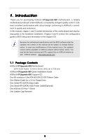
K7Upgrade-880 User Manual Version 1.0 Published August 2004 Copyright©2004 ASRock INC. All rights reserved. 1 - ASRock K7Upgrade-880 | User Manual - Page 2
any form or by any means, except duplication of documentation by the purchaser for backup purpose, without written consent of ASRock Inc. Products and corporate names appearing in this manual may or may not be registered trademarks or copyrights of their respective companies, and are used only for - ASRock K7Upgrade-880 | User Manual - Page 3
5 1.1 Package Contents 5 1.2 Specifications 6 1.3 Motherboard Layout 8 1.4 ASRock I/O Plus 9 TM ...2 . Installation 10 Pre-installation Swap Functions for SATA HDDs .......... 21 2.9 Making An SATA Driver Diskette 22 3 . BIOS SETUP UTILITY 23 3.1 Introduction 23 3.1.1 BIOS Menu Bar 23 - ASRock K7Upgrade-880 | User Manual - Page 4
4 . Software Support 42 4.1 Install Operating System 42 4.2 Support CD Information 42 4.2.1 Running Support CD 42 4.2.2 Drivers Menu 42 4.2.3 Utilities Menu 42 4.2.4 Contact Information 42 4 - ASRock K7Upgrade-880 | User Manual - Page 5
Contents ASRock K7Upgrade-880 Motherboard (ATX Form Factor: 12.0-in x 8.5-in, 30.5 cm x 21.6 cm) ASRock K7Upgrade-880 Quick Installation Guide ASRock K7Upgrade-880 Support CD One 80-conductor Ultra ATA 66/100/133 IDE Ribbon Cable One Ribbon Cable for a 3.5-in Floppy Drive One Serial ATA (SATA) Data - ASRock K7Upgrade-880 | User Manual - Page 6
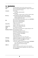
Monitor: CPU Temperature Sensing Motherboard Temperature Sensing CPU Overheat Shutdown to Protect CPU Life (ASRock U-COP)(see CAUTION 2) CPU Fan Tachometer Chassis Fan Tachometer Voltage Monitoring: +12V, +5V, +3.3V, Vcore K8 Bridge: Supports CPU upgrade from AMD K7 462-Pin CPU to AMD - ASRock K7Upgrade-880 | User Manual - Page 7
/ Microphone BIOS: AMI BIOS Supports "Plug and Play" ACPI 1.1 compliance wake up events SMBIOS 2.3.1 support CPU frequency stepless control (only for advanced users' reference, see CAUTION 5) OS: Microsoft® Windows® 98SE / ME / 2000 / XP compliant CAUTION! 1. This motherboard supports Dual - ASRock K7Upgrade-880 | User Manual - Page 8
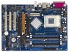
Motherboard 1 B: USB5 USB45 CD1 AUX1 Audio CODEC JR1 JL1 AUDIO1 1 LAN PHY Super I/O J6 1 J14 1 4Mb BIOS 1 GAME1 VKIACT8h8ip0set 1.5V_AGP1 1 IDE Connector (IDE2, Black) 9 Primary IDE Connector (IDE1, Blue) 10 FSB Select Jumpers (FSB_SEL0, FSB_SEL1) 11 2 x 184-pin DDR DIMM Slots (Dual - ASRock K7Upgrade-880 | User Manual - Page 9
1.4 ASRock I/O PlusTM 1 2 3 4 5 11 10 9 1 Parallel Port 2 RJ-45 Port 3 Line In (Light Blue) 4 Line Out (Lime) 5 Microphone (Pink) 6 2 x Shared USB 2.0 Ports (USB4, USB5) 8 7 6 7 2 x USB 2.0 Ports (USB0, - ASRock K7Upgrade-880 | User Manual - Page 10
2. Installation K7Upgrade-880 is an ATX form factor (12.0-in x 8.5-in, 30.5 cm x 21.6 cm) motherboard. Before you install the motherboard, study the configuration of your chassis to ensure that the motherboard fits into it. Pre-installation Precautions Take note of the following precautions before - ASRock K7Upgrade-880 | User Manual - Page 11
3 Step 4 2.2 Installation of CPU Fan and Heatsink After you install the CPU into this motherboard, it is necessary to install a larger heatsink and cooling fan to dissipate heat. You also For proper installation, please kindly refer to the instruction manuals of the CPU fan and the heatsink. 11 - ASRock K7Upgrade-880 | User Manual - Page 12
2.3 Installation of Memory Modules (DIMM) K7Upgrade-880 motherboard provides four 184-pin DDR (Double Data Rate) DIMM slots, and supports Dual Channel Memory Technology. For dual channel configuration, you always need to install identical (the same brand, speed, size and chip-type) DDR DIMM pair - ASRock K7Upgrade-880 | User Manual - Page 13
matches the break on the slot. notch break notch break The DIMM only fits in one correct orientation. It will cause permanent damage to the motherboard and the DIMM if you force the DIMM into the slot at incorrect orientation. Step 3. Firmly insert the DIMM into the slot until the retaining - ASRock K7Upgrade-880 | User Manual - Page 14
the slot AGP2 supports for K8 AGP Interface) on K7Upgrade-880 motherboard. K8 Bridge (Orange-Colored Bridge (K8BRIDGE_1) + Brown-Colored Bridge (K8BRIDGE_2)): The set of K8 Bridge allows you to upgrade your AMD 462-Pin CPU to AMD 754-Pin CPU by installing an add-on ASRock 754Bridge (optional) into - ASRock K7Upgrade-880 | User Manual - Page 15
motherboard package, and please follow the "Jumper Cap Remover Instruction" to use it properly. PCI slots: PCI slots are used to install expansion cards a graphics card. Please insert the AGP card with K7 AGP Interface into the slot 1.5V_AGP1 (see page 8 No. 37), or insert the AGP card with K8 AGP - ASRock K7Upgrade-880 | User Manual - Page 16
audio update the BIOS. If you need to clear the CMOS when you just finish updating the BIOS motherboard is by means of the adjustment of jumper-setting. To perform over clocking, you must set the FSB jumper according to your AMD CPU before you use the "Manual" option as the FSB setting in BIOS - ASRock K7Upgrade-880 | User Manual - Page 17
FID1 1 FID0 1 Note: The set of CPU Multiplier Jumper is only for advanced users to adjust the multiplier of CPU. Please follow the table below to adjust the jumper caps are not provided by ASRock. Please understand that ASRock does not guarantee and support the adjustment of multiplier. These - ASRock K7Upgrade-880 | User Manual - Page 18
ATA (SATA) connectors support SATA data cables for internal storage devices. The current SATA interface allows up to 1.5 Gb/s data transfer rate. Serial ATA (SATA) Data Cable Either end of the SATA data cable can be connected to the SATA hard disk or the SATA connector on the motherboard. 18 - ASRock K7Upgrade-880 | User Manual - Page 19
) (CD1: see p.8, No. 40) (AUX1: see p.8, No. 39) CD-R GND GND CD-L AUX-R GND GND AUX-L CD1 AUX1 These connectors allow you to receive stereo audio input from sound sources such as a CD-ROM, DVD-ROM, TV tuner card, or MPEG card. Front Panel Audio Header (9-pin AUDIO1) (see p.8, No. 35) GND +5VA - ASRock K7Upgrade-880 | User Manual - Page 20
System Panel Header (9-pin PANEL1) (see p.8, No. 22) Chassis Speaker Header (4-pin SPEAKER 1) (see p.8, No. 24) PLED+ PLEDPWRBTN# GND 1 DUMMY RESET# GND HDLEDHDLED+ 1 SPEAKER DUMMY DUMMY +5V This header accommodates several system front panel functions. Please connect the chassis speaker to this - ASRock K7Upgrade-880 | User Manual - Page 21
Connect one end of the SATA data cable to the motherboard's SATA connector. STEP 4: Connect the other end of the SATA data cable to the SATA hard disk. 2.8 Hot Plug and Hot Swap Functions for SATA HDDs K7Upgrade-880 motherboard supports Hot Plug and Hot Swap functions for SATA Devices. What is Hot - ASRock K7Upgrade-880 | User Manual - Page 22
Diskette If you want to install Windows 2000 or Windows XP on your SATA HDDs, you will need to make an SATA driver diskette before you start the OS installation. STEP 1: Insert the ASRock Support CD into your optical drive to boot your system. (Do NOT insert any floppy diskette into the floppy - ASRock K7Upgrade-880 | User Manual - Page 23
the BIOS SETUP UTILITY to configure your system. The Flash Memory on the motherboard stores the BIOS SETUP UTILITY. You may run the BIOS SETUP off and then back on. Because the BIOS software is constantly being updated, the following BIOS setup screens and descriptions are for reference purpose - ASRock K7Upgrade-880 | User Manual - Page 24
H/W Monitor Boot Security Exit System Overview System Time System Date [10:00:09] [Mon 08/02/2004] BIOS Version Processor Type Processor Speed L1 Cache Size L2 Cache Size : K7Upgrade BIOS P1.00 : AMD Athlon (tm) XP 2600+ : 2083 MHz : 64KB : 256KB Total Memory DIMM 1 DIMM 2 DIMM 3 DIMM - ASRock K7Upgrade-880 | User Manual - Page 25
K8 BRIDGE on this motherboard, you will see the below Main screen when entering the BIOS SETUP UTILITY. BIOS SETUP UTILITY Main Advanced H/W Monitor Boot Security Exit System Overview System Time System Date [17:00:09] [Mon 08/02/2004] BIOS Version : K7Upgrade-880 W/754Bridge BIOS P1.0 Processor - ASRock K7Upgrade-880 | User Manual - Page 26
stability. If you use an AMD 754-Pin CPU on the ASRock 754Bridge, which is installed into the K8 BRIDGE on this motherboard, you will see the below screens and configuration options for the CPU Configuration. BIOS SETUP UTILITY Advanced CPU Configuration CPU Host Frequency Actual Frequency (MHz - ASRock K7Upgrade-880 | User Manual - Page 27
Frequency While entering setup, BIOS auto detects the present CPU host frequency of this motherboard. The actual CPU If AUTO, FID/VID will be left at the rated frequency/voltage. If Manual, FID/VID will be set based on User Selection in Setup. +F1 F9 F10 ESC Select Screen Select Item Change Option - ASRock K7Upgrade-880 | User Manual - Page 28
Memory Clock This item can be set by the code using [Auto]. You can set one of the standard values as listed: [133 MHz (DDR266)], [166 MHz (DDR333)], [200 MHz (DDR400)]. Flexibility Option The default value of this option is [Disabled]. It will allow better tolerance for memory compatibility when it - ASRock K7Upgrade-880 | User Manual - Page 29
BIOS Strength PCI Delay Transaction OnBoard LAN OnBoard AC'97 Audio [PCI] [64MB] [Auto] [Disabled] [ [Auto] is selected, the motherboard will detect the memory module(s) 166MHz (DDR 333)], [200MHz (DDR 400)]. Flexibility Option The default value of card's specifications requires other sizes. 29 - ASRock K7Upgrade-880 | User Manual - Page 30
Disabled] for the onboard AC'97 Audio feature. If you use an AMD 754-Pin CPU on the ASRock 754Bridge, which is installed into the K8 BRIDGE on this motherboard, you will see the below screen and configuration options for the Chipset Configuration. BIOS SETUP UTILITY Advanced Chipset Settings VCCM - ASRock K7Upgrade-880 | User Manual - Page 31
] or [Disabled] for the onboard AC'97 Audio feature. HT Width You may set the HyperTransport width as [8 bit], [16 bit] or [Auto]. The default value is [Auto]. HT Speed You may set the HyperTransport speed as [Auto], [200 MHz], [400 MHz], [600 MHz], or [800 MHz]. The default value is [Auto]. 31 - ASRock K7Upgrade-880 | User Manual - Page 32
3.3.3 ACPI Configuration Advanced BIOS SETUP UTILITY ACPI Configuration Suspend To RAM Restore on AC / auto-detect or disable the Suspend-toRAM feature. Select [Auto] will enable this feature if the OS supports it. If you set this item to [Disabled], the function "Restore on AC/Power Loss" will - ASRock K7Upgrade-880 | User Manual - Page 33
" as the example in the following instruction, which can be applied to the configurations of "Secondary IDE Slave" as well. Advanced BIOS SETUP UTILITY Primary IDE Master Device Vendor :ST340014A :40.0 GB :Supported :16Sectors :4 :MultiWord DMA-2 :Ultra DMA-5 :Supported [Auto] [Auto] [Auto - ASRock K7Upgrade-880 | User Manual - Page 34
selecting the hard disk information into BIOS, use a disk utility, such as CD/DVD drives. [ARMD]: This is used for IDE ARMD (ATAPI Removable Media Device), such as MO. LBA/Large Mode Use this item to select the LBA/Large mode for a hard disk > 512 MB under DOS and Windows; for Netware and UNIX user - ASRock K7Upgrade-880 | User Manual - Page 35
recommended to keep the default value unless the installed PCI expansion cards' specifications require other settings. PCI IDE BusMaster Use this item this section, you may configure the type of your floppy drive. Advanced BIOS SETUP UTILITY Floppy Configuration Floppy A Floppy B [1.44 MB 312"] - ASRock K7Upgrade-880 | User Manual - Page 36
Channel Parallel Port IRQ OnBoard Game Port OnBoard MIDI Port [Enabled] [3F8 / IRQ4] [Disabled] [378] [ECP + EPP] [1.9] [DMA3] [IRQ7] [Enabled] [Disabled] Allow BIOS to Enable or Disable Floppy Controller. +F1 F9 F10 ESC Select Screen Select Item Change Option General Help Load Defaults Save and - ASRock K7Upgrade-880 | User Manual - Page 37
the MIDI Port or disable it. Configuration options: [Disabled], [300], and [330]. 3.3.8 USB Configuration BIOS SETUP UTILITY Advanced USB Configuration USB Controller USB 2.0 Support Legacy USB Support [Enabled] [Enabled] [Disabled] To enable or disable the onboard USB controllers. +F1 F9 F10 - ASRock K7Upgrade-880 | User Manual - Page 38
the status of the hardware on your system, including the parameters of the CPU temperature, motherboard temperature, CPU fan speed, chassis fan speed, and the critical voltage. Main Advanced BIOS SETUP UTILITY H/W Monitor Boot Security Exit Hardware Health Event Monitoring CPU Temperature - ASRock K7Upgrade-880 | User Manual - Page 39
may specify the boot sequence from the available devices in your system. BIOS SETUP UTILITY Boot Boot Device Priority 1st Boot Device 2nd Boot Device 3rd Boot Device [1st FLOPPY DRIVE] [HDD: PM-MAXTOR 6L08] [CD / DVD] Specifies the boot sequence from the available devices. A device - ASRock K7Upgrade-880 | User Manual - Page 40
, you may also clear it. Main Advanced BIOS SETUP UTILITY H/W Monitor Boot Security Exit Security Settings Supervisor Password : Not Installed User Password : Not Installed Change Supervisor Password Change User Password Clear User Password Install or Change the password. Select Screen - ASRock K7Upgrade-880 | User Manual - Page 41
and exit setup?" Select [OK] to save the changes and exit the BIOS SETUP UTILITY. Discard Changes and Exit When you select this option, it message, "Discard changes and exit setup?" Select [OK] to exit the BIOS SETUP UTILITY without saving any changes. Discard Changes When you select this option - ASRock K7Upgrade-880 | User Manual - Page 42
information. 4.2 Support CD Information The Support CD that came with the motherboard contains necessary drivers and useful utilities that enhance the motherboard features. 4.2.1 Running The Support CD To begin using the support CD, insert the CD into your CD-ROM drive. The CD automatically displays
-
 1
1 -
 2
2 -
 3
3 -
 4
4 -
 5
5 -
 6
6 -
 7
7 -
8
-
9
-
10
-
11
-
12
-
13
-
14
-
15
-
16
-
17
-
18
-
19
-
20
-
21
-
22
-
23
-
24
-
25
-
26
-
27
-
28
-
29
-
30
-
31
-
32
-
33
-
34
-
35
-
36
-
37
-
38
-
39
-
40
-
41
-
42
 |
 |

1
K7Upgrade-880
User Manual
Version 1.0
Published August 2004
Copyright©2004 ASRock INC. All rights reserved.