ASRock M266A User Manual
ASRock M266A Manual
 |
View all ASRock M266A manuals
Add to My Manuals
Save this manual to your list of manuals |
ASRock M266A manual content summary:
- ASRock M266A | User Manual - Page 1
M266A User Manual Version 1.0 Published April 2003 Copyright©2003 ASRock INC. All rights reserved. 1 - ASRock M266A | User Manual - Page 2
owners' benefit, without intent to infringe. Disclaimer: Specifications and information contained in this manual are furnished for informational use only and subject to change without notice, and should not be constructed as a commitment by ASRock. ASRock assumes no responsibility for any errors or - ASRock M266A | User Manual - Page 3
1 Introduction 4 1.1 Package Contents 4 1.2 Specifications 5 1.3 Motherboard Layout 7 1.4 ASRock I/OTM 8 2 Installation 9 2.1 Screw Holes 9 2.2 Pre-installation Precautions 9 2.3 CPU Installation 10 2.4 Installation of CPU fan and Heatsink 10 2.5 Installation of Memory Modules (DIMM 11 - ASRock M266A | User Manual - Page 4
of this manual occur, the updated version will be available on ASRock website without further notice. ASRock website http://www.asrock.com 1.1 Package Contents ASRock M266A motherboard (Micro ATX form factor: 9.6" x 9.6", 24.4 x 24.4 cm) ASRock M266A Quick Setup Guide ASRock M266A Support CD 1 Cable - ASRock M266A | User Manual - Page 5
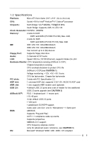
1.2 Specifications Platform: Micro ATX form factor (9.6" x 9.6", 24.4 x 24.4 cm) CPU: Socket 478 for Intel® Pentium® 4 / Celeron® processor Chipsets: North Bridge: VIA P4M266A, FSB@533 MHz; South Bridge: Supports USB 2.0, ATA 133 Clock Generator: 100 MHz - 200MHz Memory: 2 slots for DDR: - ASRock M266A | User Manual - Page 6
check if the CPU fan on the motherboard functions properly before you resume the system. To improve heat dissipation, remember to spray thermal grease between the CPU and the heatsink when you install the PC system. 2. Power Management for USB 2.0 works fine under Microsoft® Windows® XP. It may not - ASRock M266A | User Manual - Page 7
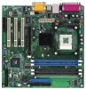
2MB BIOS AMR1 Accelerated Graphics Port PCI 1 01 23 01 23 CMOS Battery CLRCMOS1 PCI 2 PCI 3 VIA South Bridge CHA_FAN1 SPEAKER1 M266A USB45 IR1 PLED PWRBTN PANEL1 PS2_USB_PWR1 HDLED RST FLOPPY1 27 17 9 16 15 10 18 26 16 13 14 22 12 1 ATX power connector (ATXPWR1) 2 CPU socket - ASRock M266A | User Manual - Page 8
1.4 ASRock I/OTM 1 Parallel port 2 RJ-45 port 3 Game port 4 Microphone (Pink) 5 Line In (Light Blue) 6 Line Out (Lime) 7 USB 2.0 ports 8 VGA port 9 PS/2 keyboard port (Purple) 10 PS/2 mouse port (Green) 8 - ASRock M266A | User Manual - Page 9
cause physical injuries to you and damages to motherboard components. Unplug the power cord from the wall socket before touching any component. 2. To avoid damaging the motherboard components due to static electricity, NEVER place your motherboard directly on the carpet or the like. Also remember - ASRock M266A | User Manual - Page 10
Thermal grease between the CPU and the heatsink is also needed to improve heat transfer. Make sure that the CPU and the heatsink are securely fastened and in good contact with each other. For proper installation, please kindly refer to the instruction manuals of vendors of CPU fan and heatsink. 10 - ASRock M266A | User Manual - Page 11
(DIMM) SDRAM (Synchronous DRAM) DIMM (Dual In-line Memory Module) has 168 pinsand DDR (Double Data Rate) SDRAM use both 168-pin SDRAM DIMM and 184-pin DDR DIMM at the same time. To optimize the compatibility, it is not recommended to use two different models of the DIMMs at the same time. Step 1. - ASRock M266A | User Manual - Page 12
1 AGP slot on M266A motherboard. PCI slots: PCI slots are used to install expansion cards that have the 32-bit PCI interface. AMR slot: AMR slot is used to insert an AMR card with v.92 Modem functionality. AGP slot: The AGP slot is used to install a graphics card. The ASRock AGP slot has a special - ASRock M266A | User Manual - Page 13
(see p.7 item 22) +5V +5VSB +5VSB (standby) for PS/2 or USB wake up events. Note: To select +5VSB, it requires 2 Amp and higher p.7 item 17) Clear CMOS solder points Note: These solder points allow you to clear the data in the CMOS. The data in the CMOS includes system setup information - ASRock M266A | User Manual - Page 14
) (see p.7 item 13) ASRock I/OTM provides you 4 default USB 2.0 ports on the rear panel. If the rear USB ports are not sufficient, this USB 2.0 header is available for 2 additional USB 2.0 ports. Infrared module connector (5-pin IR1) (see p.7 item 14) This connector supports an optional wireless - ASRock M266A | User Manual - Page 15
CHA_FAN1) (see p.7 item 9) CPU fan connector (3-pin CPU_FAN1) (see audio input from sound sources such as AUX1 a CD-ROM, DVD-ROM, TV tuner card, or MPEG card. This is an interface for front panel audio cable that allows convenient connection and control of audio supports a serial port module. 15 - ASRock M266A | User Manual - Page 16
exactly match what you see on your screen. 3.2 BIOS Setup Utility Main Menu When you enter the BIOS Setup utility, the following screen appears: AMIBIOS SETUP UTILITY - VERSION 3.31a M266A BIOS P1.0 Standard CMOS Setup Advanced CMOS Setup Advanced Chipset Setup Power Management Setup PCI / Plug - ASRock M266A | User Manual - Page 17
bar. The following table lists the keys in the CMOS Setup [ Setup Help ] System Date System Time Floppy Drives IDE Devices BIOS Version Processor Type Processor Speed Cache Size Microcode Update Total Memory DDR1 DDR2 SDR1 SDR2 Apr 10 2003 Thu 20:07:40 M266A BIOS P1.00 Pentium (R) 4 Family CPU - ASRock M266A | User Manual - Page 18
size for the hard disk drive that you configured. [USER]: It allows user to manually enter the number of cylinders, heads, and sectors per track for the drive. , the BIOS Setup may detect incorrect parameters. In these cases, select [User] to manually enter the IDE hard disk drive parameters. 18 - ASRock M266A | User Manual - Page 19
shows the drive's maximum capacity as calculated by the BIOS based on the drive information you entered. LBA Mode mode for a hard disk > 512 MB under DOS and Windows; for Netware and UNIX user, select [Off] to disable compatible IDE devices. Set to [Disabled] to suppress Ultra DMA capability. 19 - ASRock M266A | User Manual - Page 20
3.31a Advanced CMOS Setup [ Setup by skipping memory retestings. Boot-time Diagnostic Screen: If this option is enabled, the screen will show CPU and hardware performed before BIOS setup. If [Always] option is selected, the "Password Check" is performed before both boot-up and BIOS setup. Boot - ASRock M266A | User Manual - Page 21
[Auto] The motherboard detects the jumper setup and sets the CPU host frequency automatically. [Manual] This allows user to set CPU host frequency manually. However, this is not recommended unless user thoroughly knows the feature. Wrong setup may cause problems during operation. CPU Ratio Selection - ASRock M266A | User Manual - Page 22
Enable PCI Delay Transaction feature will free the PCI Bus when the CPU is accessing 8-bit ISA cards. Disable this feature when using ISA cards that are not PCI 2.1 compliant. USB Controller Use this to enable or disable the use of USB devices. USB Device Legacy Support Use this to enable or disable - ASRock M266A | User Manual - Page 23
Power Management Setup AMIBIOS SETUP UTILITY - VERSION 3.31a Standard CMOS Setup [ Setup Help ] Suspend To RAM the ACPI Suspend-to-RAM feature. Select [Auto] will enable this feature if the system supports it. Repost Video on S3 Resume This feature allows you to repost video on S3 resume - ASRock M266A | User Manual - Page 24
Defaults F10:Save & Exit PCI Latency Timer (PCI Clocks) The default is 32. We recommend you to keep the default value unless your PCI expansion cards' specifications require other settings. Primary Graphics Adapter Select AGP or PCI as the primary graphics adapter. 24 - ASRock M266A | User Manual - Page 25
Version Parallel Port IRQ Parallel Port DMA Channel OnBoard Midi Port Midi IRQ Select OnBoard Game Port OnBoard IDE OnBoard LAN OnBoard AC' 97 Audio Auto Auto Disabled Auto ECP + EPPl 1.9 Auto Auto Disabled 5 200h Both Enabled Auto to enable or disable the floppy drive controller. F1:Help - ASRock M266A | User Manual - Page 26
set to [Disabled], it will disable the both. Configuration options: [Disabled], [Primary], [Secondary], [Both]. OnBoard LAN Enable or disable onboard LAN feature. OnBoard AC'97 Audio Enable or disable onboard AC'97 audio feature. OnBoard MC'97 Modem Enable or disable onboard MC'97 modem feature. 26 - ASRock M266A | User Manual - Page 27
the parameters for CPU temperature, Motherboard temperature, CPU fan speed, and defaults for all appropriate items in the BIOS Setup Utility. Press to CPU and the memory. You can cause fatal errors or instability if you install the optimized defaults when your hardware does not support - ASRock M266A | User Manual - Page 28
detects installed devices. Install the necessary drivers to activate the devices. 4.2.3 Utilities Menu The Utilities Menu shows the applications software that the motherboard supports. Click on a specific item then follow the installation wizard to install it. 4.2.4 ASRock PC-DIY Live Demo Program
-
 1
1 -
 2
2 -
 3
3 -
 4
4 -
 5
5 -
 6
6 -
 7
7 -
8
-
9
-
10
-
11
-
12
-
13
-
14
-
15
-
16
-
17
-
18
-
19
-
20
-
21
-
22
-
23
-
24
-
25
-
26
-
27
-
28
 |
 |

1
M266A
User Manual
Version 1.0
Published April 2003
Copyright©2003 ASRock INC. All rights reserved.