ASRock M810LMR User Manual
ASRock M810LMR Manual
 |
View all ASRock M810LMR manuals
Add to My Manuals
Save this manual to your list of manuals |
ASRock M810LMR manual content summary:
- ASRock M810LMR | User Manual - Page 1
M810LMR User Manual Version 1.0 Published January 2003 Copyright©2003 ASRock INC. All rights reserved. 1 - ASRock M810LMR | User Manual - Page 2
any form or by any means, except duplication of documentation by the purchaser for backup purpose, without written consent of ASRock Inc. Products and corporate names appearing in this manual may or may not be registered trademarks or copyrights of their respective companies, and are used only for - ASRock M810LMR | User Manual - Page 3
Motherboard Layout 6 1.4 ASRock I/OTM 7 2 Installation 8 2.1 Screw Holes 8 2.2 Pre-installation Precautions 8 2.3 CPU Installation 8 2.4 Installation of Heatsink and CPU fan 9 2.5 Installation of Memory Modules (DIMM 9 2.6 Expansion Slots 10 2.7 Jumpers Setup 10 2.8 Connectors 11 3 BIOS - ASRock M810LMR | User Manual - Page 4
occur, the updated version will be available on ASRock website without further notice. ASRock website http://www.asrock.com 1.1 Package Contents ASRock M810LMR motherboard (Micro ATX form factor: 9.6" x 7.0", 24.4 x 17.8 cm) ASRock M810LMR Quick Installation Guide ASRock AMD-VIA Series Support CD - ASRock M810LMR | User Manual - Page 5
Monitor: PCI slots: AMR slot: ASRock I/OTM: BIOS: OS: 2 channels AC'97 Audio Speed: 802.3u (10/100 Ethernet), supports Wake-On-LAN CPU temperature sensing (ASRock U-COP); Chassis temperature sensing; CPU overheat shutdown to protect CPU life (ASRock U-COP) (see CAUTION 1); Voltage monitoring - ASRock M810LMR | User Manual - Page 6
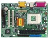
1.3 Motherboard Layout PS/2 Mouse PS/2 Keyboard 22 3 1 17.8cm (7.0 in) CPU_FAN1 1 PS2_USB_PWR1 24 1 1 HDLED RESET PANEL 1 2MB BIOS VIA South Bridge M810LMR 16 10 25 6 14 15 12 11 1 ATX Power Connector (ATXPWR1) 2 CPU Socket 3 CPU Fan Connector (CPU_FAN1) 4 North Bridge - ASRock M810LMR | User Manual - Page 7
1.4 ASRock I/OTM 1 2 3 11 10 9 8 76 5 4 1 Parallel Port 2 RJ 45 Port 3 Game Port 4 Microphone (Pink) 5 Line In (Light Blue) 6 Line Out (Lime) 7 USB 1.1 ports 2,3 on the I/O shield with the "Front USB Header Connected" sticker enclosed in the package of M810LMR motherboard. 7 - ASRock M810LMR | User Manual - Page 8
M810LMR is a Micro ATX form factor (9.6" x 7.0", 24.4 x 17.8 cm) motherboard. Before you install the motherboard, study the configuration of your chassis to ensure that the motherboard fits into it. Make sure to unplug the power cord before installing or removing the motherboard. Failure - ASRock M810LMR | User Manual - Page 9
CPU. The lever clicks on the side tab to indicate that it is locked. Step 1 Step 2, 3 Step 4 2.4 Installation of CPU Fan and Heatsink AMD AhtlonTM / AthlonTM XP the instruction manuals of vendors of CPU fan and heatsink. 2.5 Installation of Memory Modules (DIMM) M810LMR motherboard provides two - ASRock M810LMR | User Manual - Page 10
M810LMR motherboard. PCI slots: PCI slots are used to install expansion cards that have the 32-bit PCI interface. AMR slot: AMR slot is used to insert ASRock FSB_SEL1 FSB 133MHz Note: The setting of the CPU front side bus frequency of this motherboard is by means of the adjustment of jumper-setting. - ASRock M810LMR | User Manual - Page 11
Pin1. Primary IDE connector (Blue) Secondary IDE connector (Black) (39-pin IDE1, see p.6 item 7) (39-pin IDE2, see p.6 item 8) PIN1 IDE1 BLUE Connect to the motherboard PIN1 IDE2 BLACK Connect to the IDE devices 80-Pin ATA 100 cable 11 - ASRock M810LMR | User Manual - Page 12
AUX-L GND GND AUX-R AUX1 CD-L GND GND CD-R CD1 This connector supports an optional wireless transmitting and receiving infrared module. These connectors allow you to cable to the connector matching the black wire to the ground pin. CPU fan connector (3-pin CPU_FAN1) (see p.6 item 3) GND +12V - ASRock M810LMR | User Manual - Page 13
pin JUSB23) (see p.6 item 27) RRXD1 DDTR#1 DDSR#1 CCTS#1 1 RRI#1 RRTS#1 GND TTXD1 DDCD#1 1 USB_PWR P-2 P+2 GND USB_PWR P-3 P+3 GND DUMMY This COM1 header supports a serial port module. JUSB23 header is shared with the USB 1.1 ports 2,3. When using the front panel USB ports by attaching the the - ASRock M810LMR | User Manual - Page 14
BIOS Setup Utility. The Flash Memory on the motherboard stores the BIOS Setup Utility. When you start up the computer, there is a chance for you to run the BIOS the predetermined choices. Because the BIOS software is constantly being updated, the following BIOS setup screens and descriptions are for - ASRock M810LMR | User Manual - Page 15
2003 Thu 20:07:40 [ Setup Help ] Month: Jan - Dec Day: 01 - 31 Year: 1980 - 2099 M810LMR BIOS P1.00 AMD Athlon(tm) XP 2200+ 1800 MHz 128 KB 256 KB 224 MB + 32 MB Share Memory 256 MB / 133 MHz None F1:Help Esc:Exit :Select Item :Select Menu +/-:Change Values Enter:Select - ASRock M810LMR | User Manual - Page 16
may due to that the hard disk is too old or too new. If the hard disk was already formatted on an older system, the BIOS Setup may detect incorrect parameters. In these cases, select [User] to manually enter the IDE hard disk drive parameters. After entering the hard disk information into - ASRock M810LMR | User Manual - Page 17
per track. Refer to the drive documentation to determine the correct value. Maximum Capacity This field shows the drive's maximum capacity as calculated by the BIOS based on the drive information you entered. LBA Mode This allows user to select the LBA mode for a hard disk > 512 MB under DOS and - ASRock M810LMR | User Manual - Page 18
necessary drivers to activate the devices. 4.2.3 Utilities Menu The Utilities Menu shows the applications software that the motherboard supports. Click on a specific item then follow the installation wizard to install it. 4.2.4 ASRock PC-DIY Live Demo Program ASRock presents you a multimedia PC-DIY - ASRock M810LMR | User Manual - Page 19
the jumper-setting. [Manual]: This allows user to set CPU host frequency manually. However, this is not recommended unless user thoroughly knows the feature. Wrong setup may cause problems during operation. SDRAM Frequency: If set to [Auto], the motherboard detects the memory module(s) inserted and - ASRock M810LMR | User Manual - Page 20
Controller USB Device Legacy Support SDRAM CAS Latency Disabled Auto Enabled Disabled Auto [Enabled] to free the PCI bus when the CPU is accessing 8-bit ISA VGA Frame Buffer Size: This allows you to set the size of the share memory for the onboard VGA. When [Auto] is selected, the system will auto - ASRock M810LMR | User Manual - Page 21
Resource Configuration: Advanced AMIBIOS SETUP UTILITY - VERSION 3.31a Resource Configuration [ Setup Help ] PCI Latency Timer (PCI Clocks) 32 to select PCI clocks. Leave on default setting for the best PCI performance. F1:Help Esc:Previous Menu :Select Item +/-:Change Values Enter - ASRock M810LMR | User Manual - Page 22
. System Hardware Monitor: You can check the status of the hardware on your system. It allows you to monitor the parameters for CPU temperature, Motherboard temperature, CPU fan speed, and critical voltage. Advanced AMIBIOS SETUP UTILITY - VERSION 3.31a System Hardware Monitor [ Setup Help - ASRock M810LMR | User Manual - Page 23
p assword. Password Check: Select the check point for "Password Check". Configuration options: [Setup], [Always]. If [Setup] option is selected, the "Password Check" is performed before BIOS setup. If [Always] option is selected, the "Password Check" is performed before both boot-up and - ASRock M810LMR | User Manual - Page 24
3. Power Setup Menu Main Advanced AMIBIOS SETUP UTILITY - VERSION 3.31a Security Power Boot Exit Restore on AC / Power Loss Ring-In Power On PCI Devices Power On RTC Alarm Power On RTC Alarm Date RTC Alarm Hour RTC Alarm Minute RTC Alarm Second Power Off Disabled Disabled Disabled Every Day 00 - ASRock M810LMR | User Manual - Page 25
this mode will speed up the boot-up routine by skipping memory retestings. Boot Up Num-Lock: If this is set to will appear. If you press , it will save the current settings and exit the BIOS SETUP Utility. Exit Discarding Changes: After you enter the submenu, the message "Quit without saving
-
 1
1 -
 2
2 -
 3
3 -
 4
4 -
 5
5 -
 6
6 -
 7
7 -
8
-
9
-
10
-
11
-
12
-
13
-
14
-
15
-
16
-
17
-
18
-
19
-
20
-
21
-
22
-
23
-
24
-
25
 |
 |

1
M810LMR
User Manual
Version 1.0
Published January 2003
Copyright©2003 ASRock INC. All rights reserved.