ASRock P43C-ME User Manual
ASRock P43C-ME Manual
 |
View all ASRock P43C-ME manuals
Add to My Manuals
Save this manual to your list of manuals |
ASRock P43C-ME manual content summary:
- ASRock P43C-ME | User Manual - Page 1
P43C-ME User Manual Version 1.0 Published November 2009 Copyright©2009 ASRock INC. All rights reserved. 1 - ASRock P43C-ME | User Manual - Page 2
any form or by any means, except duplication of documentation by the purchaser for backup purpose, without written consent of ASRock Inc. Products and corporate names appearing in this manual may or may not be registered trademarks or copyrights of their respective companies, and are used only for - ASRock P43C-ME | User Manual - Page 3
2.4 Installation of Heatsink and CPU fan 17 2.5 Installation of Memory Modules (DIMM 18 2.6 Expansion Slots (PCI and PCI Express SATAII HDDs 29 2.13 SATA / SATAII HDD Hot Plug Feature and Operation Guide 30 2.14 Driver Installation Guide 32 2.15 Installing Windows® 7 / 7 64-bit / VistaTM / - ASRock P43C-ME | User Manual - Page 4
Screen 57 3.6 Boot Screen 58 3.6.1 Boot Settings Configuration 58 3.7 Security Screen 59 3.8 Exit Screen 60 4 Software Support 61 4.1 Install Operating System 61 4.2 Support CD Information 61 4.2.1 Running Support CD 61 4.2.2 Drivers Menu 61 4.2.3 Utilities Menu 61 4.2.4 Contact - ASRock P43C-ME | User Manual - Page 5
for specific information about the model you are using. www.asrock.com/support/index.asp 1.1 Package Contents ASRock P43C-ME Motherboard (Micro ATX Form Factor: 9.6-in x 8.3-in, 24.4 cm x 21.1 cm) ASRock P43C-ME Quick Installation Guide ASRock P43C-ME Support CD One 80-conductor Ultra ATA 66/100/133 - ASRock P43C-ME | User Manual - Page 6
1333/1066/800 non-ECC, un-buffered memory (see CAUTION 5) - Max. capacity of system memory: 8GB (see CAUTION 6) - 2 x DDR2 DIMM slots - Support DDR2 1200(OC)/1066/800/667 non-ECC, un-buffered memory (see CAUTION 5) - Max. capacity of system memory: 8GB (see CAUTION 6) - 1 x PCI Express 2.0 x16 slot - ASRock P43C-ME | User Manual - Page 7
"Plug and Play" - ACPI 1.1 Compliance Wake Up Events - AMBIOS 2.3.1 Support - CPU, DRAM, GTL, NB, SB, SB 1.1, VTT Voltage Multi-adjustment - Supports Smart BIOS - Drivers, Utilities, AntiVirus Software (Trial Version), ASRock Software Suite (CyberLink DVD Suite and Creative Sound Blaster X-Fi MB - ASRock P43C-ME | User Manual - Page 8
http://www.asrock.com WARNING Please realize that there is a certain risk involved with overclocking, including adjusting the setting in the motherboard supports Dual Channel Memory Technology. Before you implement Dual Channel Memory Technology, make sure to read the installation guide of memory - ASRock P43C-ME | User Manual - Page 9
disk to SATAII connector, please read the "SATAII Hard Disk Setup Guide" on page 28 to adjust your SATAII hard disk drive to capable of. OC DNA, an exclusive utility developed by ASRock, provides a convenient way for the user to record the OC settings and share with others. It helps you to save your - ASRock P43C-ME | User Manual - Page 10
16. EuP, stands for Energy Using Product, was a provision regulated by European Union to define the power consumption for the completed system. According to EuP, the total AC power of the completed system shall be under 1.00W in off mode condition. To meet EuP standard, an EuP ready motherboard and - ASRock P43C-ME | User Manual - Page 11
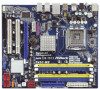
FSB3 Intel P43 Chipset CLRCMOS1 1 LPT1 1 PCIE1 1 IR1 CMOS Battery PCIE2 PCI1 AUDIO CODEC HD_AUDIO1 1 CD1 FLOPPY1 PCI2 COM1 1 Gigabit LAN PCI Express 2.0 RoHS P43C-ME DDRII_1 (64 bit, 240-pin module) DDR3_A1 (64 bit, 240-pin module) IDE1 8Mb BIOS CHA_FAN1 USB8_9 1 Intel ICH10 S ATA - ASRock P43C-ME | User Manual - Page 12
1 . 4 I/O Panel 1 2 3 6 4 7 5 8 14 13 12 11 10 9 1 PS/2 Mouse Port (Green) * 2 LAN RJ-45 Port (LAN1) 3 Side Speaker (Gray) 4 Rear Speaker (Black) 5 Central / Bass (Orange) 6 Line In (Light Blue) ** 7 Front Speaker (Lime) 8 Microphone (Pink) 9 USB 2.0 Ports (USB45) 10 USB 2.0 Ports ( - ASRock P43C-ME | User Manual - Page 13
cable to the front panel audio header. After restarting your computer, you will find "VIA HD Audio Deck" tool on your system. Please follow below instructions according to the OS you install. For Windows® XP / XP 64-bit OS: Please click "VIA HD Audio Deck" icon , and click "Speaker". Then you - ASRock P43C-ME | User Manual - Page 14
the motherboard. 2.2 Pre-installation Precautions Take note of the following precautions before you install motherboard components or change any motherboard settings. 1. Unplug the power cord from the wall socket before touching any component. 2. To avoid damaging the motherboard components due to - ASRock P43C-ME | User Manual - Page 15
2.3 CPU Installation For the installation of Intel 775-LAND CPU, please follow the steps below. 775-Pin Socket Overview Before you insert the 775-LAND CPU into the socket, please check if the CPU surface is unclean or if there is any bent pin on the socket. Do not force to insert the CPU into the - ASRock P43C-ME | User Manual - Page 16
Pick and Place Cap): Use your left hand index finger and thumb to support the load plate edge, engage PnP cap with right hand thumb and peel the PnP cap. 2. This cap must be placed if returning the motherboard for after service. Step 4. Close the socket: Step 4-1. Rotate the load plate onto the IHS. - ASRock P43C-ME | User Manual - Page 17
Heatsink This motherboard is equipped with 775-Pin socket that supports Intel 775-LAND CPU. Please adopt the type of , see page 11, No. 4). For proper installation, please kindly refer to the instruction manuals of your CPU fan and heatsink. Below is an example to illustrate the installation of - ASRock P43C-ME | User Manual - Page 18
3) DIMM slots, and supports Dual Channel Memory Technology. For dual channel memory modules, for optimal compatibility and reliability, it is recommended to install them in the slots of the same color. In other words, install them in the set of blue slots (DDR3_A1 and DDR3_B1), or in the set - ASRock P43C-ME | User Manual - Page 19
Installing a DIMM Please make sure to disconnect power supply before adding or removing DIMMs or the system components. Step 1. Step 2. Unlock a DIMM slot by pressing the retaining clips outward. Align a DIMM on the slot such that the notch on the DIMM matches the break on the slot. notch break - ASRock P43C-ME | User Manual - Page 20
read the documentation of the expansion card and make necessary hardware settings for the card before you start the installation. Step 2. Remove the bracket facing the slot that you intend to use. Keep the screws for later use. Step 4. Align the card connector with the slot and press firmly until - ASRock P43C-ME | User Manual - Page 21
and pin2 are "Short" when jumper cap is placed on these 2 pins. Jumper Setting Description PS2_USB_PWR1 (see p.11 No. 2) 1_2 +5V 2_3 +5VSB Short pin2, pin3 Otherwise, the memory module may not work properly on this motherboard. Please refer to below jumper settings. 2_3 FSB1 FSB2 4_5 FSB3 - ASRock P43C-ME | User Manual - Page 22
and try to overclock to FSB1333 orFSB1600 (by BIOS setting) you may face the problem, that DRAM frequency will beoverclocked very high. Please use the CPU may not work properly on this motherboard. Please refer to below jumper settings. FSB1 FSB2 FSB3 2_3 4_5 2_3 If you want to overclock the CPU - ASRock P43C-ME | User Manual - Page 23
devices 80-conductor ATA 66/100/133 cable Note: Please refer to the instruction of your IDE device vendor for the details. Serial ATAII Connectors (SATAII_1 ( SATAII_1 (Port 0) These six Serial ATAII (SATAII) connectors support SATA data cables for internal storage devices. The current SATAII - ASRock P43C-ME | User Manual - Page 24
there are two USB 2.0 headers on this motherboard. Each USB 2.0 header can support two USB 2.0 ports. This is an interface for print port cable that allows stereo audio input from sound sources such as a CD-ROM, DVD-ROM, TV tuner card, or MPEG card. This is an interface for front panel audio - ASRock P43C-ME | User Manual - Page 25
wire on the chassis must support HDA to function correctly. Please follow the instruction in our manual and chassis manual to install your system. 2. panel. E. Enter BIOS Setup Utility. Enter Advanced Settings, and then select Chipset Configuration. Set the Front Panel Control option from [Auto] to - ASRock P43C-ME | User Manual - Page 26
Please connect an ATX 12V power supply to this connector. This COM1 header supports a serial port module. HDMI_SPDIF header, providing SPDIF audio output to HDMI VGA card, allows the system to connect HDMI Digital TV/ projector/LCD devices. Please connect the HDMI_SPDIF connector of HDMI - ASRock P43C-ME | User Manual - Page 27
Guide HDMI (High-Definition Multi-media Interface) is an all-digital audio/video specification, which provides an interface between any compatible digital audio/ video source, such as a set-top box, DVD player, A/V receiver and a compatible TV the installation guide on page 20 manual user manual - ASRock P43C-ME | User Manual - Page 28
guide. Some default setting of SATAII hard disks may not be at SATAII mode, which operate with the best performance. In order to enable SATAII function, please follow the below instruction 's website for details: http://www.hitachigst.com/hdd/support/download.htm The above examples are just for your - ASRock P43C-ME | User Manual - Page 29
cable to the SATA / SATAII hard disk. It is not recommended to switch the "Configure SATAII as" setting after OS installation. 2.12 Hot Plug Function for SATA / SATAII HDDs P43C-ME supports Hot Plug function for SATA / SATAII Devices in AHCI mode. Intel® ICH10 south bridge chipset provides hardware - ASRock P43C-ME | User Manual - Page 30
is installed into system properly. The latest SATA / SATAII driver is available on our support website: www.asrock.com 4. Make sure to use the SATA power cable & data cable, which are from our motherboard package. 5. Please follow below instructions step by step to reduce the risk of HDD crash or - ASRock P43C-ME | User Manual - Page 31
the SATA / SATAII HDD. How to Hot Unplug a SATA / SATAII HDD: Points of attention, before you process the Hot Unplug: Please do follow below instruction sequence to process the Hot Unplug, improper procedure will cause the SATA / SATAII HDD damage and data loss. Step 1 Unplug SATA data cable from - ASRock P43C-ME | User Manual - Page 32
2.14 Driver Installation Guide To install the drivers to your system, please insert the support CD to your optical drive first. Then, the drivers compatible to your system can be auto-detected and listed on the support CD driver page. Please follow the order from up to bottom side to install those - ASRock P43C-ME | User Manual - Page 33
to boot your system, and follow the instruction to install Windows® 7 / 7 64-bit / VistaTM / VistaTM 64-bit OS on your system. When you see "Where do you want to install Windows?" page, please insert the ASRock Support CD into your optical drive, and click the "Load Driver" button on the left on the - ASRock P43C-ME | User Manual - Page 34
motherboard supports Untied Overclocking Technology, which means during overclocking, FSB enjoys better margin due to fixed PCI / PCIE buses. Before you enable Untied Overclocking function, please enter "Overclock Mode" option of BIOS setup to set the selection from [Auto] to [Manual]. Therefore - ASRock P43C-ME | User Manual - Page 35
screen. 3.1.1 BIOS Menu Bar The top of the screen has a menu bar with the following selections: Main To set up the system time/date information OC Tweaker To set up overclocking features Advanced To set up the advanced BIOS features H/W Monitor To display current hardware status Boot To - ASRock P43C-ME | User Manual - Page 36
load optimal default values for all the settings To save changes and exit the BIOS 09] [Mon 11/16/2009] BIOS Version : P43C-ME P1.00 Processor Type : Intel (R) CPU Cache Size : 1024KB Total Memory DDRII_A1 DDRII_B1 DDR3_A1 DDR3_B1 : 1024MB Single-Channel Memory Mode : 1024MB/400MHz DDR2_800 - ASRock P43C-ME | User Manual - Page 37
to load the optimized CPU overclocking setting. Please note that overclocing may cause damage to your CPU and motherboard. It should be done at your own risk and expense. DRAM Frequency If [Auto] is selected, the motherboard will detect the memory module(s) inserted and assigns appropriate frequency - ASRock P43C-ME | User Manual - Page 38
DRAM Timing Control BIOS SETUP UTILITY OC Tweaker DRAM Timing Control DRAM tCL DRAM tRCD DRAM tRP DRAM tRAS DRAM tRFC DRAM tWR DRAM tWTR DRAM tRRD DRAM tRTP 6 [Auto] 6 [Auto] 6 [Auto] 18 [Auto] 42 [Auto] 6 [Auto] 3 [Auto] 3 [Auto] 3 [Auto] DRAM tCL Value Min = 3 Max = 7 +F1 F9 F10 ESC Select - ASRock P43C-ME | User Manual - Page 39
support Intel (R) SpeedStep(tm) tech.. Please note that enabling this function may reduce CPU voltage and lead to system stability or compatibility issue with some power supplies. Please set select CPU Voltage. Configuration options: [Auto] and [Manual]. The default value is [Auto]. DRAM Voltage Use - ASRock P43C-ME | User Manual - Page 40
]. VTT Voltage Use this to select VTT Voltage. Configuration options: [Auto], [1.10V] to [1.46V]. The default value is [Auto]. Would you like to save current setting user defaults? In this option, you are allowed to load and save three user defaults according to your own requirements. 40 - ASRock P43C-ME | User Manual - Page 41
Defaults F10 Save and Exit ESC Exit v02.54 (C) Copyright 1985-2005, American Megatrends, Inc. Setting wrong values in this section may cause the system to malfunction. ASRock Instant Flash ASRock Instant Flash is a BIOS flash utility embedded in Flash ROM. This convenient BIOS update tool allows - ASRock P43C-ME | User Manual - Page 42
motherboard. Ratio CMOS Setting If the ratio status is unlocked, you will find this item appear to allow you changing the ratio value of this motherboard. Enhance Halt State All processors support the Halt State (C1). The C1 state is supported through the native processor instructions HLT and MWAIT - ASRock P43C-ME | User Manual - Page 43
hidden if the current CPU does not support No-Excute Memory Protection. Hyper Threading Technology To enable support Intel (R) SpeedStep(tm) tech.. Please note that enabling this function may reduce CPU voltage and lead to system stability or compatibility issue with some power supplies. Please set - ASRock P43C-ME | User Manual - Page 44
Clock Modulation This provides the On-Demand Clock Modulation duty cycle. It indicates the clock on to clock off interval ratio. For example, if you set this option to [75.0% On], your processor will work normally 75% of the time, and spend the other 25% slacking off. Configuration options: [Auto - ASRock P43C-ME | User Manual - Page 45
[Auto] DRAM CH0 G2 (Control1) [Auto] DRAM CH0 G3 (Control2) DRAM CH0 G4 (Clocks1) DRAM CH0 G5 (Clocks2) [Auto] [Auto] [Auto] DRAM CH1 RCOMP Settings : 54-0-8-8-0-8-0 DRAM CH1 RCOMP ODT [Auto] DRAM CH1 G0 (Data) DRAM CH1 G1 (Command) DRAM CH1 G2 (Control1) [Auto] [Auto] [Auto] DRAM CH1 G3 - ASRock P43C-ME | User Manual - Page 46
is [Auto]. DRAM CH1 G5 (Clocks2) This controls the number of DRAM CH1 G5 (Clocks2). Min: 1. Max: 15. The default value is [Auto]. DRAM tRD Settings DRAM CH0 tRD This controls the number of DRAM CH0 tRD. Min: 0. Max: 30. The default value is [Auto]. DRAM CH1 tRD This controls the - ASRock P43C-ME | User Manual - Page 47
SETUP UTILITY Advanced DRAM DLL SKEW Settings DRAM CH0 CLKSET0 SKEW Info:13-0-1-0-0-1300 DRAM CH0 CLKSET0 SKEW [Auto] DRAM CH0 CLKSET1 SKEW Info:13-0-1-0-0-1300 DRAM CH0 CLKSET1 SKEW [Auto] DRAM - ASRock P43C-ME | User Manual - Page 48
DRAM CH1 CLKSET0 SKEW This controls the number of DRAM CH1 CLKSET0 SKEW. Configuration options: [Auto], [-350 ps], [-300 ps], [-250 ps], [-200 ps], [-150 ps], [-100 ps], [-50 ps] and [Normal]. The default value is [Auto]. DRAM CH1 CLKSET1 SKEW This controls the number of DRAM CH1 CLKSET1 SKEW. - ASRock P43C-ME | User Manual - Page 49
power savings. The default value is [Disabled]. Configuration options: [Auto], [Enabled] and [Disabled]. If you want to enable this function, please set this item to [Enabled]. Besides the BIOS option, you can also choose our Intelligent Energy Saver utility to enable this function. Primary Graphics - ASRock P43C-ME | User Manual - Page 50
-toRAM feature. Select [Auto] will enable this feature if the OS supports it. If you set this item to [Disabled], the function "Repost Video on STR Resume" the feature Check Ready Bit. Restore on AC/Power Loss This allows you to set the power state after an unexpected AC/Power loss. If [Power Off] is - ASRock P43C-ME | User Manual - Page 51
Please set this Detected] [35] Options Disabled Compatible Enhanced +F1 F9 F10 ESC Configuration Please select [Compatible] when you install option "Configure SATAII as", you are allowed to set the selection to [IDE] or [AHCI]. The Interface) supports NCQ You may set the IDE configuration - ASRock P43C-ME | User Manual - Page 52
:40.0 GB :Supported :16Sectors :4 :MultiWord DMA-2 :Ultra DMA-5 :Supported [Auto] [Auto the hard disk. Make sure to set the partition of the Primary IDE hard This is used for IDE ARMD (ATAPI Removable Media Device), such as MO. LBA/Large Mode PIO Mode Use this item to set the PIO mode to enhance hard - ASRock P43C-ME | User Manual - Page 53
item to enable 32-bit access to maximize the IDE hard disk data transfer rate. 3.4.5 PCIPnP Configuration BIOS SETUP UTILITY Advanced Advanced PCI / PnP Settings PCI Latency Timer PCI IDE BusMaster [32] [Enabled] Value in units of PCI clocks for PCI device latency timer register. +F1 F9 F10 - ASRock P43C-ME | User Manual - Page 54
Megatrends, Inc. OnBoard Floppy Controller Use this item to enable or disable floppy drive controller. Serial Port Address Use this item to set the address for the onboard serial port or disable it. Configuration options: [Disabled], [3F8 / IRQ4], [2F8 / IRQ3], [3E8 / IRQ4], [2E8 / IRQ3]. Infrared - ASRock P43C-ME | User Manual - Page 55
or disable it. Configuration options: [Disabled], [378], and [278]. Parallel Port Mode Use this item to set the operation mode of the parallel port. The default value is [ECP+EPP]. If this option is set to [ECP+EPP], it will show the EPP version in the following item, "EPP Version". Configuration - ASRock P43C-ME | User Manual - Page 56
these four options: [Enabled] - Enables support for legacy USB. [Auto] - Enables legacy support if USB devices are connected. [Disabled] - USB devices are not allowed to use under legacy OS and BIOS setup when [Disabled] is selected. If you have USB compatibility issue, it is recommended to select - ASRock P43C-ME | User Manual - Page 57
The target temperature will be between 45 C/113 F and 65 C/149 F. The default value is [50 C/122 F]. Target Fan Speed Use this option to set the target fan speed. You can freely adjust the target fan speed according to the target CPU temperature that you choose. Configuration options: [Level - ASRock P43C-ME | User Manual - Page 58
F9 Load Defaults F10 Save and Exit ESC Exit v02.54 (C) Copyright 1985-2005, American Megatrends, Inc. 3.6.1 Boot Settings Configuration BIOS SETUP UTILITY Boot Boot Settings Configuration Full Screen Logo AddOn ROM Display Boot Logo Boot From Onboard LAN Bootup Num-Lock [Enabled] [Enabled] [Auto - ASRock P43C-ME | User Manual - Page 59
. This option only appears when you enable the option "Full Screen Logo". Configuration options: [Auto], [EuP], [Scenery] and [ASRock]. The default value is [Auto]. Currently, the option [Auto] is set to Aircraft. Boot From Onboard LAN Use this item to enable or disable the Boot From Onboard LAN - ASRock P43C-ME | User Manual - Page 60
operation. Load Performance Setup Default (IDE/SATA) This performance setup default may not be compatible with all system configurations. If system boot failure occurs after loading, please resume optimal default settings. F5 key can be used for this operation. Load Performance Setup AHCI Mode This - ASRock P43C-ME | User Manual - Page 61
. Because motherboard settings and hardware options vary, use the setup procedures in this chapter for general reference only. Refer to your OS documentation for more information. 4.2 Support CD Information The Support CD that came with the motherboard contains necessary drivers and useful utilities
-
 1
1 -
 2
2 -
 3
3 -
 4
4 -
 5
5 -
 6
6 -
 7
7 -
8
-
9
-
10
-
11
-
12
-
13
-
14
-
15
-
16
-
17
-
18
-
19
-
20
-
21
-
22
-
23
-
24
-
25
-
26
-
27
-
28
-
29
-
30
-
31
-
32
-
33
-
34
-
35
-
36
-
37
-
38
-
39
-
40
-
41
-
42
-
43
-
44
-
45
-
46
-
47
-
48
-
49
-
50
-
51
-
52
-
53
-
54
-
55
-
56
-
57
-
58
-
59
-
60
-
61
 |
 |

1
P43C-ME
User Manual
Version 1.0
Published November 2009
Copyright©2009 ASRock INC. All rights reserved.