ASRock P4AL-800 User Manual
ASRock P4AL-800 Manual
 |
View all ASRock P4AL-800 manuals
Add to My Manuals
Save this manual to your list of manuals |
ASRock P4AL-800 manual content summary:
- ASRock P4AL-800 | User Manual - Page 1
P4AL-800 P4AL-800M User Manual Version 1.0 Published August 2003 Copyright©2003 ASRock INC. All rights reserved. 1 - ASRock P4AL-800 | User Manual - Page 2
backup purpose, without written consent of ASRock Inc. Products and corporate names appearing in this manual may or may not be registered trademarks benefit, without intent to infringe. Disclaimer: Specifications and information contained in this manual are furnished for informational use only and - ASRock P4AL-800 | User Manual - Page 3
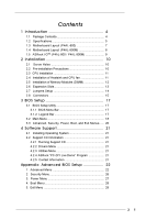
Contents 4 1.2 Specifications 5 1.3 Motherboard Layout (P4AL-800 7 1.4 Motherboard Layout (P4AL-800M 8 1.5 ASRock I/OTM (P4AL-800 / P4AL-800M 9 2 Installation 10 2.1 Screw Holes 10 2.2 Pre-installation Precautions 10 2.3 CPU Installation 11 2.4 Installation of Heatsink and CPU fan 11 - ASRock P4AL-800 | User Manual - Page 4
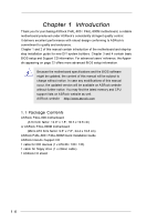
modifications of this manual occur, the updated version will be available on ASRock website without further notice. You may find the latest memory and CPU support lists on ASRock website as well. ASRock website http://www.asrock.com 1.1 Package Contents ASRock P4AL-800 motherboard (ATX form factor - ASRock P4AL-800 | User Manual - Page 5
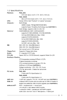
1.2 Specifications Platform: P4AL-800: ATX form factor (12.0" x 7.8", 30.5 x 19.8 cm) P4AL-800M: CPU: Micro ATX form factor (9.6" x 7.8", 24.4 x 19.8 cm) Socket 478 for Intel® Pentium® 4 / Celeron® processor Chipsets: North Bridge: A800N chipset, FSB @ 800/533/400 MHz, supports Hyper- - ASRock P4AL-800 | User Manual - Page 6
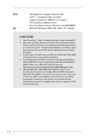
system. To improve heat dissipation, remember to spray thermal grease between the CPU and the heatsink when you install the PC system. 3. Do NOT plug a 3.3V AGP card in the AGP slot on P4AL-800 / P4AL-800M motherboard! It may cause permanent damage! 4. Power Management for USB 2.0 works fine under - ASRock P4AL-800 | User Manual - Page 7
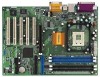
AUDIO CODEC PCI 1 Super I/O 18 2MB 11 BIOS PCI 2 ALi 16 M1563 CLRTC1 1 17 PCI 3 PCI 4 USB2.0 5.1CH CMOS Battery CHA_FAN1 PCI 5 ` P4AL-800 FLOPPY1 USB45 SPEAKER1 1 1 PANEL 1 IR1 PLED PWRBTN 1 1 HDLED RESET 9 10 13 15 14 12 1 ATX power connector (ATXPWR1) 2 CPU socket - ASRock P4AL-800 | User Manual - Page 8
23 MMIniicc in CD1 5.1CH ` AUX1 DDR400 ATA 133 20 Audio1 1 P4AL-800M JR1 JL1 26 27 AGP 8X 25 AUDIO CODEC AGP1 19 7 8 IDE1 IDE2 CMOS Battery 2MB 11 BIOS PCI 1 Super I/O PCI 2 FLOPPY1 1 USB45 ALi M1563 CHA_FAN1 IR1 1 CLRTC1 1 SPEAKER11 PLED PWRBTN PANEL 11 HDLED RESET - ASRock P4AL-800 | User Manual - Page 9
1.5 ASRock I/OTM (P4AL-800 / P4AL-800M) 1 2 3 10 9 1 Parallel port 2 RJ-45 port 3 Game port 4 Microphone (Pink) 5 Line In (Light Blue) 8 7 65 4 6 Line Out (Lime) 7 USB 2.0 ports 8 Serial port (COM1) 9 PS/2 keyboard port (Purple) 10 PS/2 mouse port (Green) 9 - ASRock P4AL-800 | User Manual - Page 10
Chapter 2 Installation P4AL-800 is an ATX form factor (12.0" x 7.8", 30.5 x 19.8 cm) motherboard; P4AL-800M is a Micro ATX form factor (9.6" x 7.8", 24.4 x 19.8 cm) motherboard. Before you install the motherboard, study the configuration of your chassis to ensure that the motherboard fits into it. - ASRock P4AL-800 | User Manual - Page 11
. Make sure that the CPU and the heatsink are securely fastened and in good contact with each other. Then connect the CPU fan to the CPU_FAN connector (CPU_FAN1, see pages 7 and 8, No. 3). For proper installation, please kindly refer to the instruction manuals of the CPU fan and heatsink vendors - ASRock P4AL-800 | User Manual - Page 12
2.5 Installation of Memory Modules (DIMM) P4AL-800 / P4AL-800M motherboard provides three 184-pin DDR (Double Data break The DIMM only fits in one correct orientation. It will cause permanent damage to the motherboard and the DIMM if you force the DIMM into the slot at incorrect orientation. Step 3. - ASRock P4AL-800 | User Manual - Page 13
AGP slot is used to install a graphics card. The ASRock AGP slot has a special locking mechanism which can securely fasten the graphics card inserted. Please do NOT plug a 3.3V AGP card in the AGP slot on P4AL-800 / P4AL-800M motherboard! It may cause permanent damage! Installing an expansion card - ASRock P4AL-800 | User Manual - Page 14
connectors can work. 2. If both jumper caps on JL1 and JR1 are removed (see fig. 2), only front panel audio works. However, it requires your front panel to support the function. CLRTC1 (see p.7/p.8 item 17) Clear CMOS 1_2 2_3 Default Clear CMOS Note: CLRTC1 allows you to clear the data in - ASRock P4AL-800 | User Manual - Page 15
this BLUE end to the motherboard 80-Pin ATA 100/133 USB_PWR P-5 P+5 GND DUMMY 1 GND P+4 P-4 USB_PWR ASRock I/OTM provides you 4 default USB 2.0 ports on supports an optional wireless transmitting and receiving infrared module. These connectors allow you to receive stereo audio input from sound - ASRock P4AL-800 | User Manual - Page 16
MIC-POWER MIC This is an interface for front panel audio cable that allows convenient connection and control of audio devices. System panel connector (9-pin PANEL1) (see p.7/p.8 the connector matching the black wire to the ground pin. CPU fan connector (3-pin CPU_FAN1) (see p.7/p.8 item 3) GND - ASRock P4AL-800 | User Manual - Page 17
Setup Utility is designed to be user-friendly. It is a menu-driven program, which allows you to scroll through its various sub-menus and select among the predetermined choices. Because the BIOS software is constantly being updated, the following BIOS setup screens and descriptions are for reference - ASRock P4AL-800 | User Manual - Page 18
Type Processor Speed Cache Size Microcode Update Total Memory DDR1 DDR2 DDR3 AMIBIOS SETUP UTILITY - VERSION 3.31a Security Power Boot Exit Aug 14 2003 Thu 10:07:40 [ Setup Help ] Month: Jan - Dec Day: 01 - 31 Year: 1980 - 2099 P4AL-800 BIOS P1.00 Pentium (R) 4 CPU 2100 MHz 512 KB F23 / 08 - ASRock P4AL-800 | User Manual - Page 19
may due to that the hard disk is too old or too new. If the hard disk was already formatted on an older system, the BIOS Setup may detect incorrect parameters. In these cases, select [User] to manually enter the IDE hard disk drive parameters. After entering the hard disk information into - ASRock P4AL-800 | User Manual - Page 20
This field shows the drive's maximum capacity as calculated by the BIOS based on the drive information you entered. LBA Mode This allows user to select the LBA mode for a hard disk > 512 , Power, Boot, and Exit Menus Detailed descriptions of these menus are listed in the Appendix. See page 22. 20 - ASRock P4AL-800 | User Manual - Page 21
detects installed devices. Install the necessary drivers to activate the devices. 4.2.3 Utilities Menu The Utilities Menu shows the applications software that the motherboard supports. Click on a specific item then follow the installation wizard to install it. 4.2.4 ASRock PC-DIY Live Demo Program - ASRock P4AL-800 | User Manual - Page 22
BIOS Setup Menu Main Advanced AMIBIOS SETUP UTILITY - VERSION 3.31a Security Power Boot Exit Spread Spectrum CPU Host Frequency Actual Frequency CPU CPU Host Frequency: This shows current CPU host frequency of the installed motherboard. CPU Ratio Selection: CPU processor that supports Hyper- - ASRock P4AL-800 | User Manual - Page 23
- VERSION 3.31a Chipset Configuration [ Setup Help ] AGP Aperture Size AGP Data Rate AGP Fast Write USB Controller USB Device Legacy Support DRAM CAS Latency CPU Thermal Throttling 64MB Auto Disabled Enabled Disabled Auto Auto to select the size of mapped memory for graphics data. F1 - ASRock P4AL-800 | User Manual - Page 24
to keep the default value unless the inserted PCI expansion cards' specifications require other settings. Primary Graphics Adapter: This allows you to select Midi IRQ Select OnBoard Game Port OnBoard IDE OnBoard LAN OnBoard AC' 97 Audio Auto Auto Disabled Auto ECP + EPP 1.9 Auto Auto Disabled 5 200 - ASRock P4AL-800 | User Manual - Page 25
], [Auto] or [Enabled] for the onboard AC'97 Audio feature. System Hardware Monitor: You can check the status of the hardware on your system. It allows you to monitor the parameters for CPU temperature, Motherboard temperature, CPU fan speed, and critical voltage. Advanced AMIBIOS SETUP UTILITY - ASRock P4AL-800 | User Manual - Page 26
password first in order to create a new password. Set User Password: Press to set User Password. Valid password can be a 1 to 6 alphanumeric Setup] option is selected, the "Password Check" is performed before BIOS setup. If [Always] option is selected, the "Password Check" is performed before - ASRock P4AL-800 | User Manual - Page 27
field allows you to select whether to auto-detect or disable the Suspend-to-RAM feature. Select [Auto] will enable this feature if the system supports it. Repost Video on STR Resume: This feature allows you to repost video on STR resume. Restore on AC/Power Loss: This allows you to - ASRock P4AL-800 | User Manual - Page 28
4. Boot Setup Menu Main Advanced AMIBIOS SETUP UTILITY - VERSION 3.31a Security Power Boot Exit Quick Boot Mode Boot Up Num-Lock Boot To OS/2 Boot From Network Enabled On No Disabled [ Setup Help ] to enable or disable the quick boot mode. Boot Device Priority F1:Help Esc:Exit : - ASRock P4AL-800 | User Manual - Page 29
the sub-menu, the message "Save current settings and exit" will appear. If you press , it will save the current settings and exit the BIOS SETUP Utility. Exit Discarding Changes: After you enter the submenu, the message "Quit without saving changes" will appear. If you press , you will
-
 1
1 -
 2
2 -
 3
3 -
 4
4 -
 5
5 -
 6
6 -
 7
7 -
8
-
9
-
10
-
11
-
12
-
13
-
14
-
15
-
16
-
17
-
18
-
19
-
20
-
21
-
22
-
23
-
24
-
25
-
26
-
27
-
28
-
29
 |
 |

1
P4AL-800
P4AL-800M
User Manual
Version 1.0
Published August 2003
Copyright©2003 ASRock INC. All rights reserved.