ASRock P67 Extreme4 Gen3 User Manual
ASRock P67 Extreme4 Gen3 Manual
 |
View all ASRock P67 Extreme4 Gen3 manuals
Add to My Manuals
Save this manual to your list of manuals |
ASRock P67 Extreme4 Gen3 manual content summary:
- ASRock P67 Extreme4 Gen3 | User Manual - Page 1
P67 Extreme4 Gen3 User Manual Version 1.0 Published June 2011 Copyright©2011 ASRock INC. All rights reserved. 1 - ASRock P67 Extreme4 Gen3 | User Manual - Page 2
commitment by ASRock. ASRock assumes no responsibility for any errors or omissions that may appear in this manual. With respect to the contents of this manual, ASRock does not , USA ONLY The Lithium battery adopted on this motherboard contains Perchlorate, a toxic substance controlled in Perchlorate - ASRock P67 Extreme4 Gen3 | User Manual - Page 3
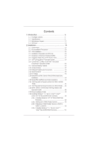
SATA / SATAII / SATA3 HDD Hot Plug Feature and Operation Guide 46 2.19 Driver Installation Guide 48 2.20 Installing Windows® 7 / 7 64-bit / VistaTM / VistaTM 64-bit / XP / XP 64-bit With RAID Functions 48 2.20.1 Installing Windows® XP / XP 64-bit With RAID Functions 48 2.20.2 Setting Up a "RAID - ASRock P67 Extreme4 Gen3 | User Manual - Page 4
ACPI Configuration 68 3.4.7 USB Configuration 69 3.5 Hardware Health Event Monitoring Screen 70 3.6 Boot Screen 71 3.7 Security Screen 72 3.8 Exit Screen 73 4 Software Support 74 4.1 Install Operating System 74 4.2 Support CD Information 74 4.2.1 Running Support CD 74 4.2.2 Drivers Menu 74 - ASRock P67 Extreme4 Gen3 | User Manual - Page 5
the model you are using. www.asrock.com/support/index.asp 1.1 Package Contents ASRock P67 Extreme4 Gen3 Motherboard (ATX Form Factor: 12.0-in x 9.6-in, 30.5 cm x 24.4 cm) ASRock P67 Extreme4 Gen3 Quick Installation Guide ASRock P67 Extreme4 Gen3 Support CD 1 x Ribbon Cable for a 3.5-in Floppy Drive - ASRock P67 Extreme4 Gen3 | User Manual - Page 6
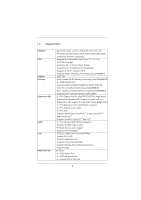
- Max. capacity of system memory: 32GB (see CAUTION 4) - Supports Intel® Extreme Memory Profile (XMP) - 2 x PCI Express 3.0 x16 slots (PCIE2/PCIE4: single at x16 or dual at x8/x8 mode) (PCI Express 3.0 with Intel® Ivy Bridge CPU, PCI Express 2.0 with Intel® Sandy Bridge CPU) - 1 x PCI Express 2.0 x16 - ASRock P67 Extreme4 Gen3 | User Manual - Page 7
- CPU/Chassis/Power FAN connector - 24 pin ATX power connector - 8 pin 12V power connector - SLI/XFire power connector - Front panel audio connector - 3 x USB 2.0 headers (support 6 USB 2.0 ports) - 1 x USB 3.0 header (supports 2 USB 3.0 ports) - 1 x Dr. Debug (7-Segment Debug LED) - 1 x Clear CMOS - ASRock P67 Extreme4 Gen3 | User Manual - Page 8
Support CD - Drivers, Utilities, AntiVirus Software (Trial Version), CyberLink MediaEspresso 6.5 Trial, ASRock Software Suite (CyberLink DVD Suite - OEM and Trial; ASRock MAGIX Multimedia Suite - OEM) Unique Feature - ASRock Extreme Tuning Utility (AXTU) (see CAUTION 6) - ASRock Instant Boot - ASRock P67 Extreme4 Gen3 | User Manual - Page 9
damage caused by overclocking. CAUTION! 1. About the setting of "Hyper Threading Technology", please check page 61. 2. This motherboard supports Dual Channel Memory Technology. Before you implement Dual Channel Memory Technology, make sure to read the installation guide of memory modules on page - ASRock P67 Extreme4 Gen3 | User Manual - Page 10
press key during the POST or press key to BIOS setup menu to access ASRock Instant Flash. Just launch this tool and save the new BIOS file to your USB flash drive, floppy disk or hard drive, then you can update your BIOS only in a few clicks without preparing an additional floppy diskette or - ASRock P67 Extreme4 Gen3 | User Manual - Page 11
to adopt three different CPU cooler types, Socket LGA 775, LGA 1155 and LGA 1156. Please be noticed that not all the 775 and 1156 CPU Fan can be used To meet EuP standard, an EuP ready motherboard and an EuP ready power supply are required. According to Intel's suggestion, the EuP ready power supply - ASRock P67 Extreme4 Gen3 | User Manual - Page 12
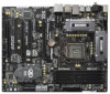
SATA3_0_1 SATA3_M1_M2 CHA_FAN1 Designed in Taipei SLI/XFIRE_PWR1 41 PCIE3 SATA2_2_3 40 PCI1 Super I/O P67 Extreme4 Gen3 39 PCIE4 RoHS Intel P67 64Mb BIOS SATA2_4_5 38 37 36 PCI2 AUDIO CODEC X ErP/EuP Ready Fast USB Front USB 3.0 HD_AUDIO1 1 HDMI_SPDIF1 COM1 1 1 PCIE5 PCI Express - ASRock P67 Extreme4 Gen3 | User Manual - Page 13
16 17 18 Microphone (Pink) IEEE 1394 Port (IEEE 1394) eSATA3 Connector USB 2.0 Ports (USB23) USB 3.0 Ports (USB01) USB 2.0 Ports (USB01) Optical SPDIF Out Port Clear CMOS Switch (CLRCBTN) PS/2 Keyboard Port (Purple) * There are two LED next to the LAN port. Please refer to the table below for the - ASRock P67 Extreme4 Gen3 | User Manual - Page 14
Primary output" to use Rear Speaker, Central/Bass, and Front Speaker, or select "Realtek HDA Audio 2nd output" to use front panel audio. *** eSATA3 connector supports SATA Gen3 in cable 1M. 14 - ASRock P67 Extreme4 Gen3 | User Manual - Page 15
. Do not over-tighten the screws! Doing so may damage the motherboard. 2.2 Pre-installation Precautions Take note of the following precautions before you install motherboard components or change any motherboard settings. 1. Unplug the power cord from the wall socket before touching any component - ASRock P67 Extreme4 Gen3 | User Manual - Page 16
of Intel 1155-Pin CPU, please follow the steps below. Load Plate Load Lever Contact Array Socket Body 1155-Pin Socket Overview Before you insert the 1155-Pin CPU into the socket, please check if the CPU the PnP cap. 2. This cap must be placed if returning the motherboard for after service. 16 - ASRock P67 Extreme4 Gen3 | User Manual - Page 17
key notches. orientation key notch alignment key Pin1 Pin1 orientation key notch 1155-Pin CPU alignment key 1155-Pin Socket For proper inserting, please ensure to match the two orientation key notches of the CPU with the two alignment keys of the socket. Step 3-3. Carefully place the - ASRock P67 Extreme4 Gen3 | User Manual - Page 18
operation or contact other components. Please be noticed that this motherboard supports Combo Cooler Option (C.C.O.), which provides the flexible option to adopt three different CPU cooler types, Socket LGA 775, LGA 1155 and LGA 1156. The white throughholes are for Socket LGA 1155/1156 CPU fan. 18 - ASRock P67 Extreme4 Gen3 | User Manual - Page 19
Memory Modules (DIMM) This motherboard provides four 240-pin DDR3 (Double Data Rate 3) DIMM slots, and supports Dual Channel Memory Technology. For dual channel configuration, you always need to install identical (the same brand, speed, size and chip two memory modules, for optimal compatibility and - ASRock P67 Extreme4 Gen3 | User Manual - Page 20
matches the break on the slot. notch break notch break The DIMM only fits in one correct orientation. It will cause permanent damage to the motherboard and the DIMM if you force the DIMM into the slot at incorrect orientation. Step 3. Firmly insert the DIMM into the slot until the retaining - ASRock P67 Extreme4 Gen3 | User Manual - Page 21
fan to motherboard chassis fan connector (CHA_FAN1, CHA_FAN2 or CHA_FAN3) when using multiple graphics cards for better thermal environment. 5. To run the PCI Express in Gen 3 speed, please must install the Ivy Bridge CPU which supports PCI Express Gen3. If you install the Sandy Bridge CPU, the PCI - ASRock P67 Extreme4 Gen3 | User Manual - Page 22
2.7 SLITM and Quad SLITM Operation Guide This motherboard supports NVIDIA® SLITM and Quad SLITM (Scalable Link Interface) technology that allows you to install up to three identical PCI Express x16 graphics cards. Currently, NVIDIA® SLITM technology supports Windows® XP / XP 64-bit / VistaTM / - ASRock P67 Extreme4 Gen3 | User Manual - Page 23
Step3. Align and insert ASRock SLI_Bridge_2S Card to the goldfingers on each graphics card. Make sure ASRock SLI_Bridge_2S Card is firmly in place. ASRock SLI_Bridge_2S Card Step4. Connect a VGA cable or a DVI cable to the monitor connector or the DVI connector of the graphics card that is inserted to - ASRock P67 Extreme4 Gen3 | User Manual - Page 24
Installation and Setup Install the graphics card drivers to your system. After that, you can the pop-up menu, select Set SLI and PhysX configuration. In Set PhysX GPU acceleration item, please select Enabled. In Select an SLI configuration item, please select Enable SLI. And click Apply. C. Reboot - ASRock P67 Extreme4 Gen3 | User Manual - Page 25
Panel tab. D. Select Control Panel tab. E. From the pop-up menu, select Set SLI and PhysX configuration. In Set PhysX GPU acceleration item, please select Enabled. In Select an SLI configuration item, please select Enable SLI. And click Apply. F. Reboot your system. G. You can freely enjoy the bene - ASRock P67 Extreme4 Gen3 | User Manual - Page 26
Guide This motherboard supports supported with Windows® XP with Service Pack 2 / VistaTM / 7 OS. 3-way CrossFireXTM and Quad CrossFireXTM feature are supported with Windows® VistaTM / 7 OS only. Please check AMD website for ATITM CrossFireXTM driver updates Setup manuals for detailed installation guide - ASRock P67 Extreme4 Gen3 | User Manual - Page 27
Step 2. Connect two Radeon graphics cards by installing CrossFire Bridge on CrossFire Bridge Interconnects on the top of Radeon graphics cards. (CrossFire Bridge is provided with the graphics card you purchase, not bundled with this motherboard. Please refer to your graphics card vendor for details - ASRock P67 Extreme4 Gen3 | User Manual - Page 28
graphics cards on PCIE2 and PCIE4 slots, and use the other CrossFireTM Bridge to connect Radeon graphics cards on PCIE4 and PCIE5 slots. (CrossFireTM Bridge is provided with the graphics card you purchase, not bundled with this motherboard. Please refer to your graphics card vendor for details.) 28 - ASRock P67 Extreme4 Gen3 | User Manual - Page 29
CrossFireTM Bridge Step 5. Connect the DVI monitor cable to the DVI connector on the Radeon graphics card on PCIE2 slot. (You may use the DVI to D-Sub adapter to convert the DVI connector to D-Sub interface, and then connect the D-Sub monitor cable to the DVI to D-Sub adapter.) 29 - ASRock P67 Extreme4 Gen3 | User Manual - Page 30
utility to uninstall any previously installed Catalyst drivers prior to installation. Please check AMD website for ATITM driver updates. Step 3. Step 4. Step 5. Install the required drivers to your system. For Windows® XP OS: A. AMD recommends Windows® XP Service Pack 2 or higher to be installed - ASRock P67 Extreme4 Gen3 | User Manual - Page 31
identification or explanation and to the owners' benefit, without intent to infringe. * For further information of AMD CrossFireXTM technology, please check AMD website for updates and details. 31 - ASRock P67 Extreme4 Gen3 | User Manual - Page 32
do not clear the CMOS right after you update the BIOS. If you need to clear the CMOS when you just finish updating the BIOS, you must boot up the system first, and then shut it down before you do the clear-CMOS action. Please be noted that the password, date, time, user default profile, 1394 GUID and - ASRock P67 Extreme4 Gen3 | User Manual - Page 33
ATAII (SATAII) connectors support SATA data cables for port on the rear I/O, the internal SATA3_M2 will not function. Either end of the SATA data cable can be connected to the SATA / SATAII / SATA3 hard disk or the SATAII / SATA3 connector on this motherboard. Please connect the black end of SATA - ASRock P67 Extreme4 Gen3 | User Manual - Page 34
default USB 2.0 ports on the I/O panel, there are three USB 2.0 headers on this motherboard. Each USB 2.0 header can support two USB 2.0 ports. Besides two default USB 3.0 ports on the I/O panel, there is one USB 3.0 header on this motherboard. This USB 3.0 header can support two USB 3.0 ports. This - ASRock P67 Extreme4 Gen3 | User Manual - Page 35
panel wire on the chassis must support HDA to function correctly. Please follow the instruction in our manual and chassis manual to install your system. 2. using the power switch. RESET (Reset Switch): Connect to the reset switch on the chassis front panel. Press the reset switch to restart the - ASRock P67 Extreme4 Gen3 | User Manual - Page 36
mainly consists of power switch, reset switch, power LED, hard drive motherboard provides 4-Pin CPU fan (Quiet Fan) support, the 3-Pin CPU fan still can work successfully even without the fan speed control function. If you plan to connect the 3-Pin CPU fan to the CPU fan connector on this motherboard - ASRock P67 Extreme4 Gen3 | User Manual - Page 37
4-Pin ATX 12V Power Supply Installation 4 1 SLI/XFIRE Power Connector (4-pin SLI/XFIRE_PWR1) (see p.12 No. 44) SLI/XFIRE_POWER1 IEEE motherboard. Besides one default IEEE 1394 port on the I/O panel, there is one IEEE 1394 header (FRONT_1394) on this motherboard. This IEEE 1394 header can support - ASRock P67 Extreme4 Gen3 | User Manual - Page 38
COM1) (see p.12 No. 34) This COM1 header supports a serial port module. HDMI_SPDIF Header (2-pin HDMI_SPDIF1) (see p.12 No. connector of HDMI VGA card to this header. The Installation Guide of Front USB 3.0 Panel Step 1 Prepare the bundled Front USB 3.0 Panel, four Step 2 Screw the 2.5" HDD/SSD - ASRock P67 Extreme4 Gen3 | User Manual - Page 39
screws into the rear USB 3.0 bracket. Step 4 Put the rear USB 3.0 bracket into the chassis. 2.12 Smart Switches The motherboard has three smart switches: power switch, reset switch and clear CMOS switch, allowing users to quickly turn on/off or reset the sytem clear the CMOS values. Power Switch - ASRock P67 Extreme4 Gen3 | User Manual - Page 40
AMI SEC error codes Microcode not found Microcode not loaded PEI Core is started Pre-memory CPU initialization is started Pre-memory CPU initialization (CPU module specific) Pre-memory CPU initialization (CPU module specific) Pre-memory CPU initialization (CPU module specific) Pre-memory North Bridge - ASRock P67 Extreme4 Gen3 | User Manual - Page 41
not match Memory initialization error. No usable memory detected Unspecified memory initialization error Memory not installed Invalid CPU type or Speed CPU mismatch CPU self test failed or possible CPU cache error CPU micro-code is not found or micro-code update is failed Internal CPU error reset PPI - ASRock P67 Extreme4 Gen3 | User Manual - Page 42
DXE Initialization (South Bridge module specific) South Bridge DXE Initialization (South Bridge module specific) ACPI module initialization CSM initialization Reserved for future AMI DXE codes OEM DXE initialization codes Boot Device Selection (BDS) phase is started Driver connecting is started PCI - ASRock P67 Extreme4 Gen3 | User Manual - Page 43
Option ROM Initialization System Reset USB hot plug PCI bus hot plug Clean-up of NVRAM Configuration Reset (reset of NVRAM settings) Reserved for future AMI codes OEM BDS initialization codes CPU initialization error North Bridge initialization error South Bridge initialization error Some of the - ASRock P67 Extreme4 Gen3 | User Manual - Page 44
motherboard adopts Intel® P67 chipset that supports Serial ATA (SATA) / Serial ATAII (SATAII) hard disks and RAID (RAID 0, RAID 1, RAID 10, RAID 5 and Intel Rapid Storage) functions. You may install SATA / SATAII hard disks on this motherboard for internal storage devices. This section will guide - ASRock P67 Extreme4 Gen3 | User Manual - Page 45
Hot Swap Functions for SATA / SATAII HDDs This motherboard supports Hot Plug and Hot Swap functions for SATA / SATAII in RAID / AHCI mode. Intel® P67 chipset provides hardware support for Advanced Host controller Interface (AHCI), a new programming interface for SATA host controllers developed thru - ASRock P67 Extreme4 Gen3 | User Manual - Page 46
is installed into system properly. The latest SATA / SATAII / SATA3 driver is available on our support website: www.asrock.com 4. Make sure to use the SATA power cable & data cable, which are from our motherboard package. 5. Please follow below instructions step by step to reduce the risk of HDD - ASRock P67 Extreme4 Gen3 | User Manual - Page 47
do follow below instruction sequence to process the Hot Plug, improper procedure will cause the SATA / SATAII / SATA3 HDD damage and data loss. Step 1 Please connect SATA power cable 1x4-pin end Step 2 Connect SATA data cable to (White) to the power supply 1x4-pin cable. the motherboard's SATAII - ASRock P67 Extreme4 Gen3 | User Manual - Page 48
, please follow below steps. STEP 1: Set up UEFI. A. Enter UEFI SETUP UTILITY Advanced screen SATA Configuration. B. Set the option "SATA Mode" to [RAID]. STEP 2: Make a SATA / SATAII / SATA3 Driver Diskette. A. Insert the Support CD into your optical drive to boot your system. B. During POST at the - ASRock P67 Extreme4 Gen3 | User Manual - Page 49
an Intel "RAID Ready" system. 1. Assemble the system and attach a single SATA / SATAII / SATA3 hard drive. 2. Set up system UEFI as step 1 of page 48. When done, exit Setup. 3. Make a SATA / SATAII / SATA3 driver diskette as step 2 of page 48. Begin Windows® setup by booting from the installation CD - ASRock P67 Extreme4 Gen3 | User Manual - Page 50
all necessary drivers. 6. Install the Intel(R) Rapid Storage software via the CD-ROM included with your motherboard or after downloading it from the Internet. This will add the Intel(R) Rapid Storage Console which can be used to manage the RAID configuration. 7. After setting up a "RAID Ready" system - ASRock P67 Extreme4 Gen3 | User Manual - Page 51
STEP 1: Set up UEFI. A. Enter UEFI SETUP UTILITY Advanced screen SATA Configuration. B. Set the option "SATA Mode" to [RAID]. STEP 2: Use "RAID Installation Guide" to set RAID configuration. Before you start to configure the RAID function, you need to check the installation guide in the Support CD for - ASRock P67 Extreme4 Gen3 | User Manual - Page 52
without RAID functions, please follow below steps. Using SATA / SATAII / SATA3 HDDs with NCQ function STEP 1: Set Up UEFI. A. Enter UEFI SETUP UTILITY Advanced screen SATA Configuration. B. Set the option "SATA Mode" to [AHCI]. STEP 2: Make a SATA / SATAII / SATA3 driver diskette. Please make a SATA - ASRock P67 Extreme4 Gen3 | User Manual - Page 53
/ VistaTM 64-bit OS on your SATA / SATAII / SATA3 HDDs without RAID functions, please follow below steps. Using SATA / SATAII / SATA3 HDDs with NCQ function STEP 1: Set Up UEFI. A. Enter UEFI SETUP UTILITY Advanced screen SATA Configuration. B. Set the option "SATA Mode" to [AHCI]. STEP 2: Install - ASRock P67 Extreme4 Gen3 | User Manual - Page 54
up overclocking features Advanced To set up the advanced UEFI features H/W Monitor To display current hardware status Boot To set up the default system device to locate and load the Operating System Security To set up the security features Exit To exit the current screen or the UEFI SETUP - ASRock P67 Extreme4 Gen3 | User Manual - Page 55
> To bring up the selected screen To display the General Help Screen To load optimal default values for all the settings To save changes and exit the UEFI SETUP UTILITY To jump to the Exit Screen or exit the current screen 3.2 Main Screen When you enter the UEFI - ASRock P67 Extreme4 Gen3 | User Manual - Page 56
will be hidden if the current CPU does not support Intel SpeedStep technology. Please note that enabling this function may reduce CPU voltage and lead to system stability or compatibility issue with some power supplies. Please set this item to [Disable] if above issue occurs. Core Current Limit Use - ASRock P67 Extreme4 Gen3 | User Manual - Page 57
value is [Auto]. DRAM Frequency If [Auto] is selected, the motherboard will detect the memory module(s) inserted and assigns appropriate frequency automatically. CAS# Latency (tCL) Use this item to change CAS# Latency (tCL) Auto/Manual setting. The default is [Auto]. RAS# to CAS# Delay (tRCD) Use - ASRock P67 Extreme4 Gen3 | User Manual - Page 58
Activate Window (tFAW) Use this item to change Four Activate Window (tFAW) Auto/Manual setting. The default is [Auto]. Memory Fast Boot Use this item to adjust DDR fast boot mode. The default value is [Auto]. Memory Power Down Mode Use this item to adjust DDR power down mode. Configuration options - ASRock P67 Extreme4 Gen3 | User Manual - Page 59
VTT Voltage Use this to select VTT Voltage. The default value is [Auto]. VCCSA Voltage Use this to select VCCSA Voltage. The default value is [Auto]. User Default In this option, you are allowed to load and save three user defaults according to your own requirements. 59 - ASRock P67 Extreme4 Gen3 | User Manual - Page 60
, South Bridge Configuration, Storage Configuration, Super IO Configuration, ACPI Configuration and USB Configuration. Setting wrong values in this section may cause the system to malfunction. Instant Flash Instant Flash is a UEFI flash utility embedded in Flash ROM. This convenient UEFI update tool - ASRock P67 Extreme4 Gen3 | User Manual - Page 61
3.4.1 CPU Configuration Intel Hyper Threading Technology To enable this feature, it requires a computer system with an Intel processor that supports Hyper-Threading technology and an operating system that includes optimization for this technology, such as Microsoft® Windows® XP / VistaTM / 7. Set to - ASRock P67 Extreme4 Gen3 | User Manual - Page 62
an enhancement to the IA-32 Intel Architecture. An IA-32 processor with "No Execute (NX) Memory Protection" can prevent data pages from being used by malicious software to execute code. This option will be hidden if the current CPU does not support No-Excute Memory Protection. Local x2APIC Use this - ASRock P67 Extreme4 Gen3 | User Manual - Page 63
]. VT-d Use this to enable or disable Intel® VT-d technology (Intel® Virtualization Technology for Directed I/O). The default value of this feature is [Disabled]. Primary Graphics Adapter This allows you to select [PCI] or [PCI Express] as the boot graphic adapter priority. The default value is [PCI - ASRock P67 Extreme4 Gen3 | User Manual - Page 64
you to set the power state after an unexpected AC/power loss. If [Power Off] is selected, the AC/power remains off when the power recovers. If [Power On] is selected, the AC/power resumes and the system starts to boot up when the power recovers. Deep Sx Mobile platforms support Deep S4 - ASRock P67 Extreme4 Gen3 | User Manual - Page 65
Onboard Debug Port LED Use this to enable or disable onboard debug port LED. The default value is [Auto]. 65 - ASRock P67 Extreme4 Gen3 | User Manual - Page 66
disable Onboard Marvell SATA3 Option ROM. If Option ROM is disabled, UEFI cannot use the SATA device to connect to Marvell SATA3 controller as Boot Device. We recommend to use Intel® P67 SATA ports (SATA3_0, SATA3_1, SATA2_2, SATA2_3, SATA2_4 and SATA2_5) for your bootable devices. This will minimum - ASRock P67 Extreme4 Gen3 | User Manual - Page 67
SATA Controller 1 Please select [Compatible] when you install legacy OS. If native OS (Windows® XP / oppy drive controller. Serial Port Use this item to enable or disable the onboard serial port. Serial Port Address Use this item to set the address for the onboard serial port. Configuration options: [ - ASRock P67 Extreme4 Gen3 | User Manual - Page 68
RAM Use this item to select whether to auto-detect or disable the Suspend-toRAM feature. Select [Auto] will enable this feature if the OS supports it. Check Ready Bit Use this item to enable or disable the feature Check Ready Bit. PS/2 Keyboard Power On Use this item to enable - ASRock P67 Extreme4 Gen3 | User Manual - Page 69
these four options: [Enabled] - Enables support for legacy USB. [Auto] - Enables legacy support if USB devices are connected. [Disabled] - USB devices are not allowed to use under legacy OS and UEFI setup when [Disabled] is selected. If you have USB compatibility issue, it is recommended to select - ASRock P67 Extreme4 Gen3 | User Manual - Page 70
CPU temperature, motherboard temperature, CPU fan speed, chassis fan speed, and the critical voltage. CPU Fan 1 & 2 Setting This allows you to set the CPU Level 4]. Chassis Fan 3 Setting This allows you to set the chassis fan 3 speed. Configuration options: [Full On] and [Manual Mode]. The default is - ASRock P67 Extreme4 Gen3 | User Manual - Page 71
Screen In this section, it will display the available devices on your system for you to configure the boot settings and the boot priority. Setup Prompt Timeout This shows the number of seconds to wait for setup activation key. 65535(0XFFFF) means indefinite waiting. Bootup Num-Lock If this item is - ASRock P67 Extreme4 Gen3 | User Manual - Page 72
3.7 Security Screen In this section, you may set or change the supervisor/user password for the system. For the user password, you may also clear it. 72 - ASRock P67 Extreme4 Gen3 | User Manual - Page 73
pop-out the following message, "Discard changes?" Select [OK] to discard all changes. Load UEFI Defaults Load UEFI default values for all the setup questions. F9 key can be used for this operation. Launch EFI Shell from filesystem device Attempts to Launch EFI Shell application (Shell64.efi) from - ASRock P67 Extreme4 Gen3 | User Manual - Page 74
XP 64-bit. Because motherboard settings and hardware options vary, use the setup procedures in this chapter for general reference only. Refer to your OS documentation for more information. 4.2 Support CD Information The Support CD that came with the motherboard contains necessary drivers and useful - ASRock P67 Extreme4 Gen3 | User Manual - Page 75
OS on a HDD Larger Than 2TB This motherboard is adopting UEFI BIOS that allows Windows® OS to be installed > at system POST. Set AHCI Mode in UEFI Setup Utility > Advanced > Storage Configuration > SATA Mode. 3. Choose the item "UEFI:xxx" to boot in UEFI Setup Utility > Boot > Boot Option #1. ("xxx"
-
 1
1 -
 2
2 -
 3
3 -
 4
4 -
 5
5 -
 6
6 -
 7
7 -
8
-
9
-
10
-
11
-
12
-
13
-
14
-
15
-
16
-
17
-
18
-
19
-
20
-
21
-
22
-
23
-
24
-
25
-
26
-
27
-
28
-
29
-
30
-
31
-
32
-
33
-
34
-
35
-
36
-
37
-
38
-
39
-
40
-
41
-
42
-
43
-
44
-
45
-
46
-
47
-
48
-
49
-
50
-
51
-
52
-
53
-
54
-
55
-
56
-
57
-
58
-
59
-
60
-
61
-
62
-
63
-
64
-
65
-
66
-
67
-
68
-
69
-
70
-
71
-
72
-
73
-
74
-
75
 |
 |

1
P67 Extreme4 Gen3
User Manual
Version 1.0
Published June 2011
Copyright©2011 ASRock INC. All rights reserved.