ASRock P67 Extreme4 Gen3 Quick Installation Guide
ASRock P67 Extreme4 Gen3 Manual
 |
View all ASRock P67 Extreme4 Gen3 manuals
Add to My Manuals
Save this manual to your list of manuals |
ASRock P67 Extreme4 Gen3 manual content summary:
- ASRock P67 Extreme4 Gen3 | Quick Installation Guide - Page 1
by ASRock. ASRock assumes no responsibility for any errors or omissions that may appear in this guide. With respect to the contents of this guide, ASRock ASRock Website: http://www.asrock.com Published June 2011 Copyright©2011 ASRock INC. All rights reserved. 1 ASRock P67 Extreme4 Gen3 Motherboard - ASRock P67 Extreme4 Gen3 | Quick Installation Guide - Page 2
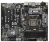
SATA3_0_1 SATA3_M1_M2 CHA_FAN1 Designed in Taipei SLI/XFIRE_PWR1 41 PCIE3 SATA2_2_3 40 PCI1 Super I/O P67 Extreme4 Gen3 39 PCIE4 RoHS Intel P67 64Mb BIOS SATA2_4_5 38 37 36 PCI2 AUDIO CODEC X ErP/EuP Ready Fast USB Front USB 3.0 HD_AUDIO1 1 HDMI_SPDIF1 COM1 1 1 PCIE5 PCI Express - ASRock P67 Extreme4 Gen3 | Quick Installation Guide - Page 3
Port (IEEE 1394) eSATA3 Connector USB 2.0 Ports (USB23) USB 3.0 Ports (USB01) USB 2.0 Ports (USB01) Optical SPDIF Out Port Clear CMOS Switch (CLRCBTN) PS/2 Keyboard Port (Purple) * There are two LED next to the LAN port 6 V V V -- 8 V V V V English 3 ASRock P67 Extreme4 Gen3 Motherboard - ASRock P67 Extreme4 Gen3 | Quick Installation Guide - Page 4
Primary output" to use Rear Speaker, Central/Bass, and Front Speaker, or select "Realtek HDA Audio 2nd output" to use front panel audio. *** eSATA3 connector supports SATA Gen3 in cable 1M. English 4 ASRock P67 Extreme4 Gen3 Motherboard - ASRock P67 Extreme4 Gen3 | Quick Installation Guide - Page 5
You... To get better performance in Windows® 7 / 7 64-bit / VistaTM / VistaTM 64bit, it is recommended to set the BIOS option in Storage Configuration to AHCI mode. For the BIOS setup, please refer to the "User Manual" in our support CD for details. 5 ASRock P67 Extreme4 Gen3 Motherboard English - ASRock P67 Extreme4 Gen3 | Quick Installation Guide - Page 6
x1 Gigabit LAN 10/100/1000 Mb/s - Realtek RTL8111E - Supports Wake-On-LAN - Supports LAN Cable Detection - Supports Energy Efficient Ethernet 802.3az - Supports PXE I/O Panel - 1 x PS/2 Mouse Port - 1 x PS/2 Keyboard Port - 1 x Coaxial SPDIF Out Port 6 ASRock P67 Extreme4 Gen3 Motherboard English - ASRock P67 Extreme4 Gen3 | Quick Installation Guide - Page 7
- Front panel audio connector - 3 x USB 2.0 headers (support 6 USB 2.0 ports) - 1 x USB 3.0 header (supports 2 USB 3.0 ports) - 1 x Dr. Debug (7-Segment Debug LED) - 1 x Clear CMOS Switch with LED - 1 x Power Switch with LED - 1 x Reset Switch with LED 7 ASRock P67 Extreme4 Gen3 Motherboard English - ASRock P67 Extreme4 Gen3 | Quick Installation Guide - Page 8
Support CD - Drivers, Utilities, AntiVirus Software (Trial Version), CyberLink MediaEspresso 6.5 Trial, ASRock Software Suite (CyberLink DVD Suite - OEM and Trial; ASRock MAGIX Multimedia Suite - OEM) Unique Feature - ASRock Extreme Tuning Utility (AXTU) (see CAUTION 6) - ASRock Instant Boot - ASRock P67 Extreme4 Gen3 | Quick Installation Guide - Page 9
overclocking. CAUTION! 1. About the setting of "Hyper Threading Technology", please check page 61 of "User Manual" in the support CD. 2. This motherboard supports Dual Channel Memory Technology. Before you implement Dual Channel Memory Technology, make sure to read the installation guide of memory - ASRock P67 Extreme4 Gen3 | Quick Installation Guide - Page 10
are currently transferring. 12. Although this motherboard offers stepless control, it is not recommended to perform over-clocking. Frequencies other than the recommended CPU bus frequencies may cause the instability of the system or damage the CPU. 10 ASRock P67 Extreme4 Gen3 Motherboard English - ASRock P67 Extreme4 Gen3 | Quick Installation Guide - Page 11
different CPU cooler types, Socket LGA 775, LGA 1155 and LGA 1156. Please be noticed that not all the 775 and 1156 CPU Fan can standard, an EuP ready motherboard and an EuP ready power supply are required. According to Intel's suggestion, the EuP ready ASRock P67 Extreme4 Gen3 Motherboard English - ASRock P67 Extreme4 Gen3 | Quick Installation Guide - Page 12
insert the 1155-Pin CPU into the socket, please check if the CPU surface is unclean or if there is any bent pin on the socket. Do not force to insert the CPU into the socket if above situation is found. Otherwise, the CPU will be seriously damaged. English 12 ASRock P67 Extreme4 Gen3 Motherboard - ASRock P67 Extreme4 Gen3 | Quick Installation Guide - Page 13
. orientation key notch alignment key Pin1 Pin1 orientation key notch 1155-Pin CPU alignment key 1155-Pin Socket For proper inserting, please ensure to match the two orientation key notches of the CPU with the two alignment keys of the socket. 13 ASRock P67 Extreme4 Gen3 Motherboard English - ASRock P67 Extreme4 Gen3 | Quick Installation Guide - Page 14
be noticed that this motherboard supports Combo Cooler Option (C.C.O.), which provides the flexible option to adopt three different CPU cooler types, Socket LGA 775, LGA 1155 and LGA 1156. The white throughholes are for Socket LGA 1155/1156 CPU fan. 14 ASRock P67 Extreme4 Gen3 Motherboard English - ASRock P67 Extreme4 Gen3 | Quick Installation Guide - Page 15
to install a DDR or DDR2 memory module into DDR3 slot; otherwise, this motherboard and DIMM may be damaged. 5. Some DDR3 1GB double-sided DIMMs with 16 chips may not work on this motherboard. It is not recommended to install them on this motherboard. English 15 ASRock P67 Extreme4 Gen3 Motherboard - ASRock P67 Extreme4 Gen3 | Quick Installation Guide - Page 16
damage to the motherboard and the DIMM if you force the DIMM into the slot at incorrect orientation. Step 3. Firmly insert the DIMM into the slot until the retaining clips at both ends fully snap back in place and the DIMM is properly seated. English 16 ASRock P67 Extreme4 Gen3 Motherboard - ASRock P67 Extreme4 Gen3 | Quick Installation Guide - Page 17
fan to motherboard chassis fan connector (CHA_FAN1, CHA_FAN2 or CHA_FAN3) when using multiple graphics cards for better thermal environment. 5. To run the PCI Express in Gen 3 speed, please must install the Ivy Bridge CPU which supports PCI Express Gen3. If you install the Sandy Bridge CPU, the PCI - ASRock P67 Extreme4 Gen3 | Quick Installation Guide - Page 18
cards that are NVIDIA® certified. 2. Make sure that your graphics card driver supports NVIDIA® SLITM technology. Download the driver from NVIDIA® website (www.nvidia.com). 3. Make sure that your power power source to the PCI Express graphics cards. 18 ASRock P67 Extreme4 Gen3 Motherboard English - ASRock P67 Extreme4 Gen3 | Quick Installation Guide - Page 19
fingers on each graphics card. Make sure ASRock SLI_Bridge_2S Card is firmly in place. ASRock SLI_Bridge_2S Card Step4. Connect a VGA cable or a DVI cable to the monitor connector or the DVI connector of the graphics card that is inserted to PCIE2 slot. 19 ASRock P67 Extreme4 Gen3 Motherboard English - ASRock P67 Extreme4 Gen3 | Quick Installation Guide - Page 20
Set SLI and PhysX configuration. In Set PhysX GPU acceleration item, please select Enabled. In Select an SLI configuration item, please select Enable SLI. And click Apply. C. Reboot your system. D. You can freely enjoy the benefit of SLITM feature. 20 ASRock P67 Extreme4 Gen3 Motherboard English - ASRock P67 Extreme4 Gen3 | Quick Installation Guide - Page 21
the pop-up menu, select Set SLI and PhysX configuration. In Set PhysX GPU acceleration item, please select Enabled. In Select an SLI configuration item, please select Enable SLI. And click Apply. F. Reboot the owners' benefit, without intent to infringe. 21 ASRock P67 Extreme4 Gen3 Motherboard English - ASRock P67 Extreme4 Gen3 | Quick Installation Guide - Page 22
the future, please refer to AMD graphics card manuals for detailed installation guide. Step 1. Insert one Radeon graphics card into PCIE2 slot and the other Radeon graphics card to PCIE4 slot. Make sure that the cards are properly seated on the slots. 22 ASRock P67 Extreme4 Gen3 Motherboard English - ASRock P67 Extreme4 Gen3 | Quick Installation Guide - Page 23
CrossFire Bridge on CrossFire Bridge Interconnects on the top of Radeon graphics cards. (CrossFire Bridge is provided with the graphics card you purchase, not bundled with this motherboard. Please D-Sub monitor cable to the DVI to D-Sub adapter.) English 23 ASRock P67 Extreme4 Gen3 Motherboard - ASRock P67 Extreme4 Gen3 | Quick Installation Guide - Page 24
the other CrossFireTM Bridge to connect Radeon graphics cards on PCIE4 and PCIE5 slots. (CrossFireTM Bridge is provided with the graphics card you purchase, not bundled with this motherboard. Please refer to your graphics card vendor for details.) 24 ASRock P67 Extreme4 Gen3 Motherboard English - ASRock P67 Extreme4 Gen3 | Quick Installation Guide - Page 25
D-Sub adapter to convert the DVI connector to D-Sub interface, and then connect the D-Sub monitor cable to the DVI to D-Sub adapter.) English 25 ASRock P67 Extreme4 Gen3 Motherboard - ASRock P67 Extreme4 Gen3 | Quick Installation Guide - Page 26
drivers prior to installation. Please check AMD website for ATITM driver updates. Step 3. Step 4. Step 5. Install the required drivers to your system. For Windows® XP OS: A. AMD recommends Windows® XP Service install three Radeon graphics cards). English 26 ASRock P67 Extreme4 Gen3 Motherboard - ASRock P67 Extreme4 Gen3 | Quick Installation Guide - Page 27
identification or explanation and to the owners' benefit, without intent to infringe. * For further information of AMD CrossFireXTM technology, please check AMD website for updates and details. 27 ASRock P67 Extreme4 Gen3 Motherboard English - ASRock P67 Extreme4 Gen3 | Quick Installation Guide - Page 28
you do the clear-CMOS action. Please be noted that the password, date, time, user default profile, 1394 GUID and MAC address will be cleared only if the CMOS battery is removed. The Clear CMOS Switch has the same function as the Clear CMOS jumper. English 28 ASRock P67 Extreme4 Gen3 Motherboard - ASRock P67 Extreme4 Gen3 | Quick Installation Guide - Page 29
support SATA data SATA HDD power connector connect to the power supply Please connect the black end of SATA power cable to the power connector on each drive. Then connect the white end of SATA power cable to the power connector of the power supply. 29 ASRock P67 Extreme4 Gen3 Motherboard - ASRock P67 Extreme4 Gen3 | Quick Installation Guide - Page 30
motherboard. This USB 3.0 header can support two USB 3.0 ports. This header supports an optional wireless transmitting and receiving infrared module. This is an interface for front panel audio cable that allows convenient connection and control of audio devices. English 30 ASRock P67 Extreme4 Gen3 - ASRock P67 Extreme4 Gen3 | Quick Installation Guide - Page 31
the chassis must support HDA to function correctly. Please follow the instruction in our manual and chassis manual to install your system power switch. RESET (Reset Switch): Connect to the reset switch on the chassis front panel. Press the reset switch to restart ASRock P67 Extreme4 Gen3 Motherboard - ASRock P67 Extreme4 Gen3 | Quick Installation Guide - Page 32
) support, the 3-Pin CPU fan still can work successfully even without the fan speed control function. If you plan to connect the 3-Pin CPU fan to the CPU fan connector on this motherboard, please connect it to Pin 1-3. Pin 1-3 Connected 3-Pin Fan Installation 32 ASRock P67 Extreme4 Gen3 Motherboard - ASRock P67 Extreme4 Gen3 | Quick Installation Guide - Page 33
disk power connecor when two graphics cards are plugged to this motherboard. Besides one default IEEE 1394 port on the I/O panel, there is one IEEE 1394 header (FRONT_1394) on this motherboard. This IEEE 1394 header can support one IEEE 1394 port. English 33 ASRock P67 Extreme4 Gen3 Motherboard - ASRock P67 Extreme4 Gen3 | Quick Installation Guide - Page 34
COM1 header supports a serial port module. HDMI_SPDIF USB 3.0 Panel to the drive bay with six chassis screws. Step 5 Plug the Front USB 3.0 cable into the USB 3.0 Step 6 The Front USB 3.0 Panel is ready to use. header (USB3_2_3) on the motherboard. English 34 ASRock P67 Extreme4 Gen3 Motherboard - ASRock P67 Extreme4 Gen3 | Quick Installation Guide - Page 35
Step 1 Unscrew the two screws from the Front USB 3.0 Step 2 Put the USB 3.0 cable and the rear USB 3.0 Panel. bracket together. Step 3 Screw the two screws into the rear USB 3.0 bracket. Step 4 Put the rear USB 3.0 bracket into the chassis. English 35 ASRock P67 Extreme4 Gen3 Motherboard - ASRock P67 Extreme4 Gen3 | Quick Installation Guide - Page 36
) (see p.2 No. 22) RESET Reset Switch is a smart switch, allowing users to quickly reset the system. Clear CMOS Switch (CLRCBTN) (see p.3 No. 17) clr CMOS Clear CMOS Switch is a smart switch, allowing users to quickly clear the CMOS values. English 36 ASRock P67 Extreme4 Gen3 Motherboard - ASRock P67 Extreme4 Gen3 | Quick Installation Guide - Page 37
. Cache initialization CPU post-memory initialization. Application Processor(s) (AP) initialization CPU post-memory initialization. Boot Strap Processor (BSP) selection CPU post-memory initialization. System Management Mode (SMM) initialization 37 ASRock P67 Extreme4 Gen3 Motherboard English - ASRock P67 Extreme4 Gen3 | Quick Installation Guide - Page 38
image is found Recovery firmware image is loaded Reserved for future AMI progress codes Recovery PPI is not available Recovery capsule is not found Invalid recovery capsule Reserved for future AMI error codes DXE Core is started NVRAM initialization English 38 ASRock P67 Extreme4 Gen3 Motherboard - ASRock P67 Extreme4 Gen3 | Quick Installation Guide - Page 39
Console input devices connect Super IO Initialization USB initialization is started USB Reset USB Detect USB Enable Reserved for future AMI codes IDE initialization is started IDE Reset IDE Detect IDE Enable SCSI initialization is started SCSI Reset English 39 ASRock P67 Extreme4 Gen3 Motherboard - ASRock P67 Extreme4 Gen3 | Quick Installation Guide - Page 40
ROM No Console Output Devices are found No Console Input Devices are found Invalid password Error loading Boot Option (LoadImage returned error) Boot Option is failed (StartImage returned error) Flash update is failed Reset protocol is not available English 40 ASRock P67 Extreme4 Gen3 Motherboard - ASRock P67 Extreme4 Gen3 | Quick Installation Guide - Page 41
below steps. Using SATA / SATAII / SATA3 HDDs without NCQ function STEP 1: Set up UEFI. A. Enter UEFI SETUP UTILITY Advanced screen SATA Configuration. B. Set the option "SATA Mode" to [IDE]. STEP 2: Install Windows® XP / XP 64-bit OS on your system. 41 ASRock P67 Extreme4 Gen3 Motherboard English - ASRock P67 Extreme4 Gen3 | Quick Installation Guide - Page 42
Using SATA / SATAII / SATA3 HDDs with NCQ function STEP 1: Set Up UEFI. A. Enter UEFI SETUP UTILITY Advanced screen SATA Configuration. B. Set the option "SATA Mode" to [AHCI]. STEP 2: Install Windows® 7 / 7 64-bit / VistaTM / VistaTM 64-bit OS on your system. 42 ASRock P67 Extreme4 Gen3 Motherboard - ASRock P67 Extreme4 Gen3 | Quick Installation Guide - Page 43
CD-ROM drive. It will display the Main Menu automatically if "AUTORUN" is enabled in your computer. If the Main Menu does not appear automatically, locate and double-click on the file "ASSETUP.EXE" from the BIN folder in the Support CD to display the menus. 43 ASRock P67 Extreme4 Gen3 Motherboard - ASRock P67 Extreme4 Gen3 | Quick Installation Guide - Page 44
Sie bitte unsere Webseite: www.asrock.com/support/index.asp 1.1 Kartoninhalt ASRock P67 Extreme4 Gen3 Motherboard (ATX-Formfaktor: 30.5 cm x 24.4 cm; 12.0 Zoll x 9.6 Zoll) ASRock P67 Extreme4 Gen3 Schnellinstallationsanleitung ASRock P67 Extreme4 Gen3 Support-CD Ein Flachbandkabel für ein 3,5-Zoll - ASRock P67 Extreme4 Gen3 | Quick Installation Guide - Page 45
Intel® Extreme Memory Profile (XMP) - 2 x PCI Express 3.0 x16-Steckplätze (PCIE2/PCIE4: einzeln im x16- oder doppelt im x8/x8Modus) (PCI Express 3.0 mit Intel® Ivy Bridge-Prozessor, PCI Express 2.0 mit Intel® Sandy Bridge 802.3az - Unterstützt PXE 45 ASRock P67 Extreme4 Gen3 Motherboard Deutsch - ASRock P67 Extreme4 Gen3 | Quick Installation Guide - Page 46
üsse Deutsch - 1 x Infrarot-Modul-Header - 1 x COM-Anschluss-Header - 1 x HDMI_SPDIF-Anschluss - 1 x IEEE 1394-Anschluss - 1 x Betriebs-LED-Header - CPU/Gehäuse/Stromlüfter-Anschluss - 24-pin ATX-Netz-Header - 8-pin anschluss für 12V-ATX-Netzteil 46 ASRock P67 Extreme4 Gen3 Motherboard - ASRock P67 Extreme4 Gen3 | Quick Installation Guide - Page 47
- Drehzahlmessung für CPU/Gehäuse/Stromlüfter - Geräuscharmer CPU-/Gehäuselüfter (ermöglicht die au tomatische Anpassung der Gehäuselüftergeschwindigkeit durch CPU-Temperatur) - Mehrstufige Geschwindigkeitsteuerung für CPU-/ Gehäuselüfter 47 ASRock P67 Extreme4 Gen3 Motherboard - ASRock P67 Extreme4 Gen3 | Quick Installation Guide - Page 48
zeigt Ihnen zur Anpassung Lüftergeschwindigkeit und Temperatur an. Bei der Übertaktung können Sie die CPU-Frequenz zur Erzielung optimaler Systemleistung übertakten. OC DNA ermöglicht Ihnen die Speicherung Ihrer OC-Einstellungen als Profil, welches Sie 48 ASRock P67 Extreme4 Gen3 Motherboard Deutsch - ASRock P67 Extreme4 Gen3 | Quick Installation Guide - Page 49
in Verbindung bleiben. Die SmartView-Funktionen können Sie mit den Windows®-Betriebssystemen 7 / 7, 64 Bit / VistaTM / VistaTM 64 Bit und dem Internet Explorer ab Version 8 nutzen. ASRock-Website: http:// www.asrock.com/Feature/SmartView/index.asp 49 ASRock P67 Extreme4 Gen3 Motherboard Deutsch - ASRock P67 Extreme4 Gen3 | Quick Installation Guide - Page 50
verschiedenen CPU-Kühlertypen, Socket LGA 775, LGA 1155 und LGA 1156. Beachten Sie bitte, dass nicht alle 775 und 1156 CPU-Lüfter EuP-fähiges Motherboard und eine EuP-fähige Stromversorgung erforderlich. Gemäß einer Empfehlung von Intel muss eine ASRock P67 Extreme4 Gen3 Motherboard Deutsch - ASRock P67 Extreme4 Gen3 | Quick Installation Guide - Page 51
-Pin Sockel Übersicht Bevor Sie die 1155-Pin CPU in den Sockel sitzen, prüfen Sie bitte, ob die CPU-Oberfläche sauber ist und keine der Kontakte verbogen sind. Setzen Sie die CPU nicht mit Gewalt in den Sockel, dies kann die CPU schwer beschädigen. Deutsch 51 ASRock P67 Extreme4 Gen3 Motherboard - ASRock P67 Extreme4 Gen3 | Quick Installation Guide - Page 52
mit dem IHS (Integrated Heat Sink - integrierter Kühlkörper) nach oben. Suchen Sie Pin 1 und die zwei Orientierungseinkerbungen. Orientierungskerbe Ausrichtungsmarkierung Pin1 Pin1 Orientierungskerbe 1155-Pin CPU Ausrichtungsmarkierung 1155-Pin Sockel 52 ASRock P67 Extreme4 Gen3 Motherboard - ASRock P67 Extreme4 Gen3 | Quick Installation Guide - Page 53
. Schritt 3-3. Drücken Sie die CPU vorsichtig in vertikaler Richtung in den Sockel. Schritt 3-4. Prüfen Sie, dass die CPU ordnungsgemäß im Sockel sitzt und die . Schritt 4-3. Sichern Sie Ladehebel und Ladeplatte mithilfe des Hebelverschlusses. 53 ASRock P67 Extreme4 Gen3 Motherboard Deutsch - ASRock P67 Extreme4 Gen3 | Quick Installation Guide - Page 54
Motherboard die Combo-Kühleroption unterstützt, die eine flexible Möglichkeit zur Aufnahme von drei verschiedenen CPU-Kühlertypen, Socket LGA 775, LGA 1155 und LGA 1156, bietet. Das weiße Durchgangsloch ist für den CPU-Lüfter im Socket LGA 1155/1156 vorgesehen. Deutsch 54 ASRock P67 Extreme4 Gen3 - ASRock P67 Extreme4 Gen3 | Quick Installation Guide - Page 55
; andernfalls könnten Motherboard und DIMMs beschädigt werden. 5. Einige doppelseitige 1 GB-DDR3-DIMMs mit 16 Chips funktionieren möglicherweise nicht auf diesem Motherboard. Wir empfehlen, sie nicht auf diesem Motherboard zu installieren. Deutsch 55 ASRock P67 Extreme4 Gen3 Motherboard - ASRock P67 Extreme4 Gen3 | Quick Installation Guide - Page 56
die Steckplätze, so dass die Halteklammern an beiden Enden des Moduls einschnappen und das DIMM-Modul fest an Ort und Stelle sitzt. Deutsch 56 ASRock P67 Extreme4 Gen3 Motherboard - ASRock P67 Extreme4 Gen3 | Quick Installation Guide - Page 57
laufen kann, installieren Sie bitte einen Ivy Bridge-Prozessor, der PCI Express 3.0 unterstützt. Wenn Sie einen Sandy Bridge-Prozessor installieren, läuft PCI Express nur den Sie nutzen möchten und behalten die Schraube für den Einbau der Karte. 57 ASRock P67 Extreme4 Gen3 Motherboard Deutsch - ASRock P67 Extreme4 Gen3 | Quick Installation Guide - Page 58
von den Betriebssystemen Windows® XP mit Service Pack 2 / VistaTM / 7 unterst Updates gibt. Beachten Sie den detailliert erklärten Installationsablauf auf Seite 22. 2.7 "Surround Display" Dieses Motherboard Support-CD: ..\ Surround Display Information Deutsch 58 ASRock P67 Extreme4 Gen3 Motherboard - ASRock P67 Extreme4 Gen3 | Quick Installation Guide - Page 59
herunter. Bitte beachten Sie, dass Kennwort, Datum, Uhrzeit, benutzerdefiniertes Profil, 1394 GUID und MAC-Adresse nur gelöscht werden, wenn die CMOS-Batterie entfernt wird. Der CMOS löschen-Schalter hat dieselbe Funktion wie der CMOS löschen-Jumper. Deutsch 59 ASRock P67 Extreme4 Gen3 Motherboard - ASRock P67 Extreme4 Gen3 | Quick Installation Guide - Page 60
Die aktuelle SATA3- Schnittstelle ermöglicht eine Datenübertragungsrate bis 6,0 Gb/s. SJedes Ende des SATA Datenkabels kann an die SATA / SATAII / SATA3 Festplatte oder das SATAII / SATA3 Verbindungsstück auf dieser Hauptplatine angeschlossen werden. Deutsch 60 ASRock P67 Extreme4 Gen3 Motherboard - ASRock P67 Extreme4 Gen3 | Quick Installation Guide - Page 61
am Motherboard. Pro USB 2.0Anschlussleiste werden zwei USB 2.0-Ports unterstützt. Neben zwei Standard-USB 3.0-Ports am E/A-Panel befindet sich ein USB 3.0Header an diesem Motherboard. Dieser USB 3.0Header kann zwei USB 3.0Ports unterstützen. Deutsch 61 ASRock P67 Extreme4 Gen3 Motherboard - ASRock P67 Extreme4 Gen3 | Quick Installation Guide - Page 62
. Passen Sie die „Recording Volume" (Aufnahmelautstärke) an. System Panel-Header (9-pin PANEL1) (siehe S.2 - No. 24) Dieser Header unterstützt mehrere Funktion der Systemvorderseite. Deutsch 62 ASRock P67 Extreme4 Gen3 Motherboard - ASRock P67 Extreme4 Gen3 | Quick Installation Guide - Page 63
des Ein-/Ausschalters ausgeschaltet werden können soll. RESET (Reset-Taste): Zum Anschließen der Reset-Taste an der Frontblende des Gehäuses. Mit der Reset-Taste können Sie den Computer im Falle eines S4- oder S5-Zustand (ausgeschaltet) leuchtet die LED nicht. 63 ASRock P67 Extreme4 Gen3 Motherboard - ASRock P67 Extreme4 Gen3 | Quick Installation Guide - Page 64
einen dreipoligen CPU-Lüfter an den CPU-Lüferanschluss dieses Motherboards anschließ ATX-Netzteil verwendet werden. Um ein 20-pol. ATX-Netzteil zu verwenden, stecken Sie den Stecker mit Pin 1 und Pin 13 ein. Installation eines 20-pol. ATX-Netzteils 1 13 64 ASRock P67 Extreme4 Gen3 Motherboard - ASRock P67 Extreme4 Gen3 | Quick Installation Guide - Page 65
der 4-Pin ATX 12V Energieversorgung 4 1 SLI/XFIRE-Stromanschluss (4-pin SLI/XFIRE_POWER1) (siehe S.2 - No. 44) SLI/XFIRE_POWER1 Sie mü -1394 Port unterstützen. Dieser COM-AnschlussHeader wird verwendet, um ein COM-Anschlussmodul zu unterstützen. Deutsch 65 ASRock P67 Extreme4 Gen3 Motherboard - ASRock P67 Extreme4 Gen3 | Quick Installation Guide - Page 66
Sie die USB 3.0-Frontblende mit sechs Gehäuseschrauben am Festplatteneinschub. Schritt 5 Schließen Sie das Kabel der USB 3.0-Frontblende am USB 3.0-Header (USB3_2_3) am Motherboard an. Schritt 6 Die USB 3.0-Frontblende ist nun einsatzbereit. Deutsch 66 ASRock P67 Extreme4 Gen3 Motherboard - ASRock P67 Extreme4 Gen3 | Quick Installation Guide - Page 67
ein Schnellschalter, mit dem Benutzer das System schnell zurücksetzen können. CMOS löschen-Schalter (CLRCBTN) (siehe S.3 - No. 17) clr CMOS Der CMOS löschen-Schalter ist ein Schnellschalter, mit dem Benutzer die CMOS-Werte schnell löschen können. 67 ASRock P67 Extreme4 Gen3 Motherboard Deutsch - ASRock P67 Extreme4 Gen3 | Quick Installation Guide - Page 68
1: UEFI einrichten. A. Rufen Sie das UEFI SETUP UTILITY auf, wählen Sie den „Advanced"- Bildschirm (Erweitert), dann „SATA Configuration". B. Stellen Sie "SATA Mode" auf [IDE]. SCHRITT 2: Installieren Sie Windows® XP / XP 64-Bit in Ihrem System. 68 ASRock P67 Extreme4 Gen3 Motherboard Deutsch - ASRock P67 Extreme4 Gen3 | Quick Installation Guide - Page 69
A. Rufen Sie das UEFI SETUP UTILITY auf, wählen Sie den „Advanced"- Bildschirm (Erweitert), dann „SATA Configuration". B. Stellen Sie "SATA Mode" auf [AHCI]. SCHRITT 2: Installieren Sie Windows® 7 / 7 64-Bit / VistaTM / VistaTM 64-Bit in Ihrem System. 69 ASRock P67 Extreme4 Gen3 Motherboard Deutsch - ASRock P67 Extreme4 Gen3 | Quick Installation Guide - Page 70
der Support-CD, um die Menüs aufzurufen. Das Setup-Programm soll es Ihnen so leicht wie möglich machen. Es ist menügesteuert, d.h. Sie können in den verschiedenen Untermenüs Ihre Auswahl treffen und die Programme werden dann automatisch installiert. 70 ASRock P67 Extreme4 Gen3 Motherboard Deutsch - ASRock P67 Extreme4 Gen3 | Quick Installation Guide - Page 71
sous Windows® 7 / 7 64 bits / VistaTM / VistaTM 64 bits, il est recommandé de paramétrer l'option BIOS dans Configuration de stockage en mode AHCI. Pour plus de détails sur l'installation BIOS, référez-vous au "Mode d'emploi" sur votre CD de support. 71 ASRock P67 Extreme4 Gen3 Motherboard Français - ASRock P67 Extreme4 Gen3 | Quick Installation Guide - Page 72
mode x16 ou double en mode x8/x8) (PCI Express 3.0 avec CPU Intel® Ivy Bridge, PCI Express 2.0 avec CPU Intel® Sandy Bridge) - 1 x slot PCI Express 2.0 x16 (PCIE5: mode x4) - Support du Wake-On-LAN - Prise en charge de la détection de câble LAN 72 ASRock P67 Extreme4 Gen3 Motherboard Français - ASRock P67 Extreme4 Gen3 | Quick Installation Guide - Page 73
Hot Plug » (Branche ment à chaud) - 4 x connecteurs SATA3, prennent en charge un taux de transfert de données pouvant aller jusqu'à 6.0Go/s - 1 x Port Disquette - 1 x En-tête du module infrarouge - 1 x En-tête de port COM - 1 x Connecteur HDMI_SPDIF 73 ASRock P67 Extreme4 Gen3 Motherboard Français - ASRock P67 Extreme4 Gen3 | Quick Installation Guide - Page 74
LAN (voir ATTENTION 11) - L'accélérateur hybride: - Contrôle direct de la fréquence CPU (voir ATTENTION 12) - ASRock U-COP (voir ATTENTION 13) - Garde d'échec au démarrage (B.F.G.) - Combo Cooler Option (C.C.O.) (voir ATTENTION 14) - DEL veilleuse 74 ASRock P67 Extreme4 Gen3 Motherboard - ASRock P67 Extreme4 Gen3 | Quick Installation Guide - Page 75
, 6-canaux et 8-canaux. Veuillez vous référer au tableau en page 3 pour effectuer la bonne connexion. 6. ASRock Extreme Tuning Utility (AXTU) est un utilitaire tout-en-un qui permet de régler précisément différentes fonctions du système, via une 75 ASRock P67 Extreme4 Gen3 Motherboard Français - ASRock P67 Extreme4 Gen3 | Quick Installation Guide - Page 76
mères ASRock sont équipées en exclusivité de l'utilitaire SmartView, ce qui vous permet de garder le contact avec vos amis itinérants. Pour utiliser la fonction SmartView, veuillez vous assurez que votre version de système d'exploitation est Windows® 76 ASRock P67 Extreme4 Gen3 Motherboard Fran - ASRock P67 Extreme4 Gen3 | Quick Installation Guide - Page 77
ASRock : http://www.asrock.com/Feature/SmartView/ index.asp 10. ASRock XFast USB permet d'améliorer les performances de votre périphérique de stockage USB CPU, les sockets LGA 775, LGA 1155 et LGA 1156. Veuillez noter que tous les ventilateurs de CPU Intel ASRock P67 Extreme4 Gen3 Motherboard Français - ASRock P67 Extreme4 Gen3 | Quick Installation Guide - Page 78
4. A chaque désinstallation de composant, placez-le sur un support antistatique ou dans son sachet d'origine. 5. Lorsque vous placez les la carte mère. 2.1 Installation du CPU Pour l'installation du processeur Intel 1155 broches, veuillez suivre la procédure ASRock P67 Extreme4 Gen3 Motherboard - ASRock P67 Extreme4 Gen3 | Quick Installation Guide - Page 79
en place si vous renvoyez la carte mère pour service après vente. Etape 3. Insérez le processeur 1155 broches : Etape 3-1. Tenez le processeur par ses bords 1 Encoche d'orientation Processeur 1155 broches Détrompeur Socket 1155 broches ASRock P67 Extreme4 Gen3 Motherboard broche 1 79 Français - ASRock P67 Extreme4 Gen3 | Quick Installation Guide - Page 80
reporter aux manuels d'instructions de votre ventilateur 1155 broches. Etape 1. Appliquez le matériau d'interface thermique au centre de IHS sur la surface du socket. (Appliquez le matériau d'interface thermique) Apply Thermal Interface Material Français 80 ASRock P67 Extreme4 Gen3 Motherboard - ASRock P67 Extreme4 Gen3 | Quick Installation Guide - Page 81
Combo Cooler Option (C.C.O.), qui offre un choix flexible pour adopter trois types différents de refroidisseurs de CPU, les sockets LGA 775, LGA 1155 et LGA 1156. Les trous traversant blancs sont pour le ventilateur de CPU au socket LGA 1155/1156. Français 81 ASRock P67 Extreme4 Gen3 Motherboard - ASRock P67 Extreme4 Gen3 | Quick Installation Guide - Page 82
des modules m émoire [DIMM] La carte mère P67 Extreme4 Gen3 dispose de quatre emplacements DIMM DDR3 (Double Data Rate 3) de 240-broches, et supporte la Technologie de Mémoire à Canal Double. Pour carte mère et les DIMM pourraient être endommagés. Français 82 ASRock P67 Extreme4 Gen3 Motherboard - ASRock P67 Extreme4 Gen3 | Quick Installation Guide - Page 83
jusqu'à ce que les clips de maintien situés aux deux extrémités se ferment complètement et que le module DIMM soit inséré correctement. 83 ASRock P67 Extreme4 Gen3 Motherboard - ASRock P67 Extreme4 Gen3 | Quick Installation Guide - Page 84
Slots PCI Express) Il y a 2 ports PCI et 5 ports PCI Express sur la carte mère P67 Extreme4 Gen3. Slots PCI: Les slots PCI sont utilis veuillez installer le CPU Ivy Bridge qui supporte PCI Express Gen3. Si vous installez le CPU Sandy Bridge, PCI Express ne . 84 ASRock P67 Extreme4 Gen3 Motherboard - ASRock P67 Extreme4 Gen3 | Quick Installation Guide - Page 85
pouvez facilement jouir des avantages de la caractéristique de l'affichage Surround. Pour les instructions détaillées, veuillez vous reporter au document qui se trouve sur le chemin suivant dans le CD d'assistance : ..\ Surround Display Information 85 ASRock P67 Extreme4 Gen3 Motherboard Français - ASRock P67 Extreme4 Gen3 | Quick Installation Guide - Page 86
que le mot de passe, la date, l'heure, le profil par défaut de l'utilisateur, 1394 GUID et l'adresse MAC seront effacés seulement si la batterie du CMOS est enlevée. Le commutateur Effacer CMOS présente la même fonction que le cavalier Effacer CMOS. Français 86 ASRock P67 Extreme4 Gen3 Motherboard - ASRock P67 Extreme4 Gen3 | Quick Installation Guide - Page 87
internes. L'interface SATA3 actuelle permet des taux transferts de données pouvant aller jusqu'à 6,0 Gb/s. Toute cote du cable de data SATA peut etre connecte au disque dur SATA / SATAII / SATA3 ou au connecteur SATAII / SATA3 sur la carte mere. Français 87 ASRock P67 Extreme4 Gen3 Motherboard - ASRock P67 Extreme4 Gen3 | Quick Installation Guide - Page 88
carte mère. Chaque embase USB 2.0 peut prendre en charge 2 ports USB 2.0. En plus des deux ports USB 3.0 par défaut sur le panneau E/S, il y a une barrette USB 3.0 sur la carte mère. Cette barrette USB 3.0 peut prendre en charge deux ports USB 3.0. Français 88 ASRock P67 Extreme4 Gen3 Motherboard - ASRock P67 Extreme4 Gen3 | Quick Installation Guide - Page 89
OUT_RET 1 OUT2_L J_SENSE OUT2_R MIC2_R MIC2_L Cet en-tête supporte un module infrarouge optionnel de transfert et de réception sans charge le HDA pour fonctionner correctement. Veuillez suivre les instructions dans notre manuel et le manuel de châssis afin ASRock P67 Extreme4 Gen3 Motherboard - ASRock P67 Extreme4 Gen3 | Quick Installation Guide - Page 90
gurer la façon de mettre votre système hors tension avec l'interrupteur d'alimentation. RESET (Interrupteur de réinitialisation): Connectez ici le connecteur de réinitialisation sur le panneau avant du correspondre le fil noir à la broche de terre. Français 90 ASRock P67 Extreme4 Gen3 Motherboard - ASRock P67 Extreme4 Gen3 | Quick Installation Guide - Page 91
offre un support de (Ventilateur silencieux ventilateur de CPU à 4 broches , le ventilateur de CPU à 3 ATX 1 13 Connecteur ATX 12V (ATX12V1 br.8) (voir p.2 No. 1) 8 5 4 1 Veuillez connecter une unité d'alimentation électrique ATX 12V sur ce connecteur. 91 ASRock P67 Extreme4 Gen3 Motherboard - ASRock P67 Extreme4 Gen3 | Quick Installation Guide - Page 92
4 broches ATX 12V 4 1 Connecteur d'alimentation SLI/XFIRE (SLI/XFIRE_POWER1 br. 4) (voir p.2 No. 44) SLI/XFIRE_POWER1 Il IEEE 1394 peut supporter un port de IEEE 1394. Cette en-tête de port COM est utilisée pour prendre en charge un module de port COM. Franç ASRock P67 Extreme4 Gen3 Motherboard - ASRock P67 Extreme4 Gen3 | Quick Installation Guide - Page 93
ère USB 3.0 Étape 1 Dévissez les deux vis du panneau avant USB 3.0. Étape 2 Assemblez le câble USB 3.0 et le support arrière USB 3.0. Étape 3 Vissez les deux vis dans le support arrière USB 3.0. Étape 4 Placez le support arrière USB 3.0 dans le châssis. 93 ASRock P67 Extreme4 Gen3 Motherboard - ASRock P67 Extreme4 Gen3 | Quick Installation Guide - Page 94
(voir p.2 No. 22) RESET Interrupteur d'effacement de CMOS (CLRCBTN) (voir p.3 No. 17) clr CMOS L'interrupteur d'alimentation est un interrupteur CMOS est un interrupteur rapide qui permet à l'utilisateur d'effacer rapidement les valeurs du CMOS. Français 94 ASRock P67 Extreme4 Gen3 Motherboard - ASRock P67 Extreme4 Gen3 | Quick Installation Guide - Page 95
1 : Configurez le UEFI. A. Accédez à UEFI SETUP UTILITY (Utilitaire de configuration UEFI) → écran Avancé → Configuration SATA. B. Réglez «SATA Mode « sur [IDE]. ETAPE 2 : Installez le système d'exploitation Windows® XP / XP 64 bits sur votre système. 95 ASRock P67 Extreme4 Gen3 Motherboard Français - ASRock P67 Extreme4 Gen3 | Quick Installation Guide - Page 96
A. Accédez à UEFI SETUP UTILITY (Utilitaire de configuration UEFI) → écran Avancé → Configuration SATA. B. Réglez «SATA Mode « sur [AHCI]. ETAPE 2: Installer le système d'exploitation Windows® 7 / 7 64-bit / VistaTM / VistaTM 64-bit sur votre système. 96 ASRock P67 Extreme4 Gen3 Motherboard Français - ASRock P67 Extreme4 Gen3 | Quick Installation Guide - Page 97
BIOS, veuillez consulter le Guide de l'utilisateur (fichier PDF) dans le CD technique. 4. Informations sur le CD de support Cette carte mère supporte divers CD technique le fichier "ASSETUP.EXE" dans le dossier BIN et doublecliquez dessus pour afficher les menus. 97 ASRock P67 Extreme4 Gen3 Motherboard - ASRock P67 Extreme4 Gen3 | Quick Installation Guide - Page 98
/ VistaTM 64-bit, si consiglia di impostare l'opzione BIOS in Storage Configuration (Configurazione di archiviazione) sulla modalità AHCI. Per l'impostazione BIOS, fare riferimento a "User Manual" (Manuale dell'utente) nel CD di supporto per dettagli. 98 ASRock P67 Extreme4 Gen3 Motherboard Italiano - ASRock P67 Extreme4 Gen3 | Quick Installation Guide - Page 99
Intel® XMP (Extreme Memory Profile) - 2 x Alloggi PCI Express 3.0 x16 (PCIE2/PCIE4: singolo a modalità x16 o doppio a modalità x8/x8) (PCI Express 3.0 con CPU Intel® Ivy Bridge, PCI Express 2.0 con CPU Intel® Sandy Bridge - 1 x porta PS/2 per mouse 99 ASRock P67 Extreme4 Gen3 Motherboard Italiano - ASRock P67 Extreme4 Gen3 | Quick Installation Guide - Page 100
ATX - 8-pin connettore ATX 12V - Collettore alimentazione SLI/XFIRE - Connettore audio sul pannello frontale - 3 x Collettore USB 2.0 (supporta 6 porte USB 2.0) - 1 x Collettore USB 3.0 (supporta 2 porte USB 3.0) - 1 x Dr. Debug (LED debug con 7 segmenti) ASRock P67 Extreme4 Gen3 Motherboard - ASRock P67 Extreme4 Gen3 | Quick Installation Guide - Page 101
della ventola dello chassis in base alla temperatura della CPU) - Ventola CPU/chassis con controllo di varie velocità - Voltaggio: +12V, +5V, +3.3V, Vcore - Microsoft® Windows® 7 / 7 64 bit / VistaTM / VistaTM 64 bit / XP / XP 64 bit - FCC, CE, WHQL 101 ASRock P67 Extreme4 Gen3 Motherboard Italiano - ASRock P67 Extreme4 Gen3 | Quick Installation Guide - Page 102
migliorare l'efficienza quando i core CPU sono inattivi senza sacrificare le prestazioni di computazione. Vistare il nostro per informazioni sulle procedure operative dell'utilità AXTU (ASRock Extreme Tuning Utility). Sito ASRock: http://www.asrock.com ASRock P67 Extreme4 Gen3 Motherboard Italiano - ASRock P67 Extreme4 Gen3 | Quick Installation Guide - Page 103
se questa motherboard offre il controllo stepless, non si consiglia di effettuare l'overclocking. Frequenze del bus del processore diverse da quelle raccomandate possono causare instabilità al sistema o danni al processore e alla scheda madre. ASRock P67 Extreme4 Gen3 Motherboard 103 Italiano - ASRock P67 Extreme4 Gen3 | Quick Installation Guide - Page 104
di calore CPU, Socket LGA 775, LGA 1155 e LGA 1156. Notare che non possono essere usate tutte le ventole CPU 775 e una scheda elettrica predisposti EuP. In base ai suggerimenti Intel l'alimentatore predisposto EuP deve soddisfare lo standard secondo cui ASRock P67 Extreme4 Gen3 Motherboard Italiano - ASRock P67 Extreme4 Gen3 | Quick Installation Guide - Page 105
la CPU da 1155-Pin nel socket, verificare che la superficie della CPU sia pulita e che non ci siano pin piegati nel socket. Non forzare l'inserimento della CPU nel socket se ci sono pin piegati. In caso contrario la CPU potrebbe essere seriamente danneggiata. 105 ASRock P67 Extreme4 Gen3 Motherboard - ASRock P67 Extreme4 Gen3 | Quick Installation Guide - Page 106
integrato) verso l'alto. Individuare il Pin1 ed i due dentelli chiave d'orientamento. Dente di orientamento Pin1 Tacca di allineamento Linea nera Italiano 106 Dente di orientamento CPU da 1155-Pin Tacca di allineamento Socket da 1155-Pin Pin1 ASRock P67 Extreme4 Gen3 Motherboard - ASRock P67 Extreme4 Gen3 | Quick Installation Guide - Page 107
di allineamento della CPU con le due tacche nel socket. Fase 3-3. Collocare con delicatezza la CPU sulla presa con un movimento puramente verticale. Fase 3-4. Verificare che la CPU sia all'interno della linguetta di ritenzione della leva di carico. 107 ASRock P67 Extreme4 Gen3 Motherboard Italiano - ASRock P67 Extreme4 Gen3 | Quick Installation Guide - Page 108
scheda mare supporta l'opzione C.C.O. (Combo Cooler Option), che fornisce la flessibilità di impiegare tre tipi diversi di dispersori di calore CPU, Socket LGA 775, LGA 1155 e LGA 1156. I fori di colore bianco sono per la ventola CPU Socket LGA 1155/1156. 108 ASRock P67 Extreme4 Gen3 Motherboard - ASRock P67 Extreme4 Gen3 | Quick Installation Guide - Page 109
DDR2 nello slot DDR3, altrimenti si possono danneggiare questa scheda madre e la DIMM. 5. Alcune DIMM DDR3 da 1GB doppio lato con 16 chip potrebbero non funzionare su questa scheda madre. Non se ne raccomanda l'installazione su questa scheda madre. Italiano 109 ASRock P67 Extreme4 Gen3 Motherboard - ASRock P67 Extreme4 Gen3 | Quick Installation Guide - Page 110
nello slot fino a far scattare completamente in posizione i fermagli di ritegno alle due estremità e fino ad installare correttamente la DIMM nella sua sede. Italiano 110 ASRock P67 Extreme4 Gen3 Motherboard - ASRock P67 Extreme4 Gen3 | Quick Installation Guide - Page 111
PCI Express alla velocità Gen 3, bisogna installare la CPU Ivy Bridge che supporta PCI Express Gen3. Se si installa la CPU Sandy Bridge, PCI Express girerà soltanto alla velocità PCI Express . Step 4. Agganciare la scheda allo chassis con le viti. Italiano 111 ASRock P67 Extreme4 Gen3 Motherboard - ASRock P67 Extreme4 Gen3 | Quick Installation Guide - Page 112
supportata solo dai sistemi operativi Windows® XP con Service Pack 2 / VistaTM / 7. La funzione il sito AMD per gli aggiornamenti dei driver ATITM CrossFireXTM. Attenersi alle procedure d'installazione, CD di supporto: ..\ Surround Display Information 112 ASRock P67 Extreme4 Gen3 Motherboard Italiano - ASRock P67 Extreme4 Gen3 | Quick Installation Guide - Page 113
della CMOS. Notare che password, data, ore, profilo utente predefinito, 1394 GUID e indirizzo MAC saranno cancellati solo se è rimossa la batteria della CMOS. L'interruttore Clear CMOS (Cancella CMOS) ha la stessa funzione del jumper Clear CMOS. Italiano 113 ASRock P67 Extreme4 Gen3 Motherboard - ASRock P67 Extreme4 Gen3 | Quick Installation Guide - Page 114
. L'interfaccia SATA3 attuale permette velocità di trasferimento dati fino a 6.0 Gb/s. Una o altra estremità del cavo di dati SATA può essere collegata al disco rigido SATA / SATAII / SATA3 o al connettore di SATAII / SATA3 su questa cartolina base. Italiano 114 ASRock P67 Extreme4 Gen3 Motherboard - ASRock P67 Extreme4 Gen3 | Quick Installation Guide - Page 115
la scheda madre dispone di tre intestazioni USB 2.0. Ciascuna intestazione USB 2.0 supporta due porte USB 2.0. Oltre alle due porte USB 3.0 standard del pannello I/O, questa scheda madre è dotata di un header USB 3.0 che supporta due porte USB 3.0. Italiano 115 ASRock P67 Extreme4 Gen3 Motherboard - ASRock P67 Extreme4 Gen3 | Quick Installation Guide - Page 116
far sì che questa operi in modo corretto. Attenersi alle istruzioni del nostro manuale e del manuale del telaio per installare il sistema. 2. Se si utilizza un pannello audio Questo collettore accomoda diverse funzioni di sistema pannello frontale. Italiano 116 ASRock P67 Extreme4 Gen3 Motherboard - ASRock P67 Extreme4 Gen3 | Quick Installation Guide - Page 117
d'alimentazione si può configurare il modo in cui si spegne il sistema. RESET (interruttore di ripristino): Va collegato all'interruttore di ripristino del pannello frontale del telaio stato S1. Il LED è spento in stato S3/S4 o S5 (spegnimento). Italiano 117 ASRock P67 Extreme4 Gen3 Motherboard - ASRock P67 Extreme4 Gen3 | Quick Installation Guide - Page 118
un 12 24 connettore elettrico ATX a 24 pin, ma può funzionare lo stesso se si adotta un alimentatore ATX a 20 pin. Per usare l'alimentatore ATX a 20 pin, collegare l'alimentatore con il Pin 1 e il Pin 13. Installazione dell'alimentatore ATX a 20 pin 1 13 ASRock P67 Extreme4 Gen3 Motherboard - ASRock P67 Extreme4 Gen3 | Quick Installation Guide - Page 119
Pin 5. 8 5 Installazione elettrica 4-Pin ATX 12V 4 1 Connettore alimentazione SLI/XFIRE (4-pin SLI/XFIRE_POWER1) (voir p.2 Nr. 44) SLI/XFIRE_POWER1 Intestazione IEEE 1394 (9-pin FRONT_1394) (vedi HDMI_SPDIF della scheda VGA HDMI a questo header. ASRock P67 Extreme4 Gen3 Motherboard 119 - ASRock P67 Extreme4 Gen3 | Quick Installation Guide - Page 120
1 Svitare le due viti dal pannello USB 3.0 anteriore. Punto 2 Collegare il cavo USB 3.0 e il supporto USB 3.0 posteriore. Punto 3 Avvitare le due viti nel supporto USB 3.0 Punto 4 Inserire il supporto USB 3.0 posteriore. posteriore nel telaio. Italiano 120 ASRock P67 Extreme4 Gen3 Motherboard - ASRock P67 Extreme4 Gen3 | Quick Installation Guide - Page 121
il sistema. L'interruttore di reset è un interruttore rapido che consente agli utenti di resettare rapidamente il sistema. L'interruttore di pulizia CMOS è un interruttore rapido che consente agli utenti di cancellare velocemente i valori CMOS. Italiano 121 ASRock P67 Extreme4 Gen3 Motherboard - ASRock P67 Extreme4 Gen3 | Quick Installation Guide - Page 122
Passo 1: Configurare il UEFI. A. Entrare in UEFI SETUP UTILITY (UTILITÀ DI CONFIGURAZIONE DEL UEFI) → Advanced screen (Avanzate) → SATA Configuration. B. Impostare "SATA Mode" su [IDE]. Passo 2: Installazione di Windows® XP / XP 64-bit sul sistema. 122 ASRock P67 Extreme4 Gen3 Motherboard Italiano - ASRock P67 Extreme4 Gen3 | Quick Installation Guide - Page 123
UEFI. A. Entrare in UEFI SETUP UTILITY (UTILITÀ DI CONFIGURAZIONE DEL UEFI) → Advanced screen (Avanzate) → SATA Configuration. B. Impostare "SATA Mode" su [AHCI]. Passo 2: Installazione di Windows® 7 / 7 64-bit / VistaTM / VistaTM 64-bit sul sistema. 123 ASRock P67 Extreme4 Gen3 Motherboard Italiano - ASRock P67 Extreme4 Gen3 | Quick Installation Guide - Page 124
"AUTORUN" è attivata nel computer, apparirà automaticamente il Menù principale. Se il Menù principale non appare automaticamente, posizionarsi sul file "ASSETUP.EXE" nel CESTINO del CD di supporto e cliccare due volte per visualizzare i menù. 124 ASRock P67 Extreme4 Gen3 Motherboard Italiano - ASRock P67 Extreme4 Gen3 | Quick Installation Guide - Page 125
/ VistaTM 64 bits, es recomendable establecer la opción del BIOS de la configuración de almacenamiento en el modo AHCI. Para obtener detalles sobre la configuración del BIOS, consulte el "Manual del usuario" que se encuentra en nuestro CD de soporte. 125 ASRock P67 Extreme4 Gen3 Motherboard Español - ASRock P67 Extreme4 Gen3 | Quick Installation Guide - Page 126
del sistema: 32GB (vea ATENCIÓN 4) - Compatible con Intel® Extreme Memory Profile (XMP) - 2 x ranuras PCI Express 3.0 x16 (PCIE2/PCIE4: sencillas en modo x16 o dobles en modo x8 / x8) (PCI Express 3.0 con CPU Intel® Ivy Bridge, PCI Express 2.0 con CPU Intel® San dy Bridge) - 1 x ranura PCI Express - ASRock P67 Extreme4 Gen3 | Quick Installation Guide - Page 127
- 1 x Cabezal de Módulo Infrarrojos - 1x En-tête de port COM - 1 x cabecera HDMI_SPDIF - 1 x cabecera IEEE 1394 - 1 x cabecera de indicador LED de encendido - Conector de ventilador de CPU / chasis / alimentación - 24-pin cabezal de alimentación ATX 127 ASRock P67 Extreme4 Gen3 Motherboard Español - ASRock P67 Extreme4 Gen3 | Quick Installation Guide - Page 128
ATENCIÓN 14) - Indicador LED nocturno - Sensibilidad a la temperatura del procesador - Sensibilidad a la temperatura de la placa madre - Taquímetros de los ventiladores del procesador y del CPU / chasis / alimentación ASRock P67 Extreme4 Gen3 Motherboard - ASRock P67 Extreme4 Gen3 | Quick Installation Guide - Page 129
del BIOS, aplicando del Manual del Usuario en el soporte CD sobre Para equipos con Windows® OS con CPU de 64-bit, no existe ASRock Extreme Tuning Utility (AXTU) es una herramienta todo en uno que permite realizar ajustes precisos en diferentes funciones del sistema ASRock P67 Extreme4 Gen3 Motherboard - ASRock P67 Extreme4 Gen3 | Quick Installation Guide - Page 130
, su historial, sus amigos de Facebook y su fuente de noticias en una vista mejorada para disfrutar de una experiencia en Internet más personal. Las placas base ASRock están exclusivamente equipadas con la utilidad ASRock P67 Extreme4 Gen3 Motherboard - ASRock P67 Extreme4 Gen3 | Quick Installation Guide - Page 131
CPU diferentes, correspondientes a los zócalos LGA 775, LGA 1155 y LGA 1156. Recuerde que no es posible el uso de todos los ventiladores para CPU con la directiva EuP. Según las directrices de Intel, una fuente de alimentación que cumpla con la ASRock P67 Extreme4 Gen3 Motherboard 131 Español - ASRock P67 Extreme4 Gen3 | Quick Installation Guide - Page 132
ón de la CPU Intel de 1155 agujas, siga CPU se encuentra limpia y no hay ninguna aguja torcida en el socket. No introduzca la CPU en el socket por la fuerza si se produce la situación anterior. Si lo hace, puede producir daños graves en la CPU. Español 132 ASRock P67 Extreme4 Gen3 Motherboard - ASRock P67 Extreme4 Gen3 | Quick Installation Guide - Page 133
IHS (Integrated Heat Sink) mirando hacia arriba. Busque la aguja 1 y las dos muescas de orientación. Muesca de orientación Tecla de alineación aguja 1 Muesca de orientación CPU de 1155 agujas Tecla de alineación Socket de 1155 agujas ASRock P67 Extreme4 Gen3 Motherboard aguja 1 133 Español - ASRock P67 Extreme4 Gen3 | Quick Installation Guide - Page 134
para ilustrar la instalación del disipador para la CPU de 1155 agujas. Paso 1. Aplique el material termal de interfaz en el centro del IHS de la superficie del socket. (Aplique el material termal de interfaz) Apply Thermal Interface Material Español 134 ASRock P67 Extreme4 Gen3 Motherboard - ASRock P67 Extreme4 Gen3 | Quick Installation Guide - Page 135
opción flexible que puede adaptarse a tres tipos de disipador de CPU diferentes, correspondientes a los zócalos LGA 775, LGA 1155 y LGA 1156. Los orificios perforados de color blanco están destinados al ventilador de CPU para zócalos LGA 1155/1156. Español 135 ASRock P67 Extreme4 Gen3 Motherboard - ASRock P67 Extreme4 Gen3 | Quick Installation Guide - Page 136
2.3 Instalación de Memoria La placa P67 Extreme4 Gen3 ofrece cuatro ranuras DIMM DDR3 de 240 pines, y soporta Tecnología de Memoria de Doble Canal. Para la confi la ranura DDR3; si lo hace, esta placa base y los módulos DIMM pueden resultar dañados. Español 136 ASRock P67 Extreme4 Gen3 Motherboard - ASRock P67 Extreme4 Gen3 | Quick Installation Guide - Page 137
5. Algunos módulos de doble cara de 1 GB DDR3 con 16 chips puede que no funcionen en esta placa base. Por tanto, no es recomendable instalarlos en ambos lados queden completamente introducidos en su sitio y la DIMM se haya asentado apropiadamente. 137 ASRock P67 Extreme4 Gen3 Motherboard Español - ASRock P67 Extreme4 Gen3 | Quick Installation Guide - Page 138
funcione a una velocidad Gen 3 generación debe instalar la CPU Ivy Bridge, que admite PCI Express Gen3. Si instala la CPU Sandy Bridge, PCI Express solamente funcionará a velocidad PCI Express Gen 2. que corresponde a la ranura que desea utilizar. Español 138 ASRock P67 Extreme4 Gen3 Motherboard - ASRock P67 Extreme4 Gen3 | Quick Installation Guide - Page 139
la ranura. Paso 4. Asegure la tarjeta con tornillos. 2.5 Manual de uso de SLITM y Quad SLITM Esta placa base es compatible con las tecnologías NVIDIA® SLITM y Quad SLITM ( en la siguiente ruta del CD de soporte: ..\ Surround Display Information 139 ASRock P67 Extreme4 Gen3 Motherboard Español - ASRock P67 Extreme4 Gen3 | Quick Installation Guide - Page 140
en cuenta que la contraseña, la fecha, la hora, el perfil predeterminado del usuario, el GUID 1394 y la dirección MAC solamente se borrará si la batería CMOS se quita. El conmutador Borrar CMOS tiene la misma función que el puente Borrar CMOS. Español 140 ASRock P67 Extreme4 Gen3 Motherboard - ASRock P67 Extreme4 Gen3 | Quick Installation Guide - Page 141
interfaz SATAII / SATA3 actual permite una velocidad de transferencia de 6.0 Gb/s. Cualquier extremo del cable de los datos de SATA puede ser conectado con el disco duro de SATA / SATAII / SATA3 o el conectador de SATAII / SATA3 en esta placa base. Español 141 ASRock P67 Extreme4 Gen3 Motherboard - ASRock P67 Extreme4 Gen3 | Quick Installation Guide - Page 142
dos puertos 3.0 predeterminados situados en el panel E/S, encontrará una cabecera USB 3.0 en esta placa base. Esta cabecera USB 3.0 admiten dos puertos USB 3.0. Este cabezal soporta un módulo infrarrojos de transmisión y recepción wireless opcional. 142 ASRock P67 Extreme4 Gen3 Motherboard Español - ASRock P67 Extreme4 Gen3 | Quick Installation Guide - Page 143
en el chasis debe soportar HDA para operar correctamente. Por favor, siga las instrucciones en nuestro manual y en el manual de chasis para instalar su sistema. 2. Si utiliza el panel de sonido AC'97, instá su sistema mediante el interruptor de alimentación. 143 ASRock P67 Extreme4 Gen3 Motherboard - ASRock P67 Extreme4 Gen3 | Quick Installation Guide - Page 144
) (vea p.2, N. 9) FAN_SPEED_CONTROL CHA_FAN_SPEED +12V GND ventilador a los conectores de ventilador, haciendo coincidir el cable negro con la patilla de (3-pin CHA_FAN2) masa. (vea p.2, N. 46) 144 ASRock P67 Extreme4 Gen3 Motherboard Español - ASRock P67 Extreme4 Gen3 | Quick Installation Guide - Page 145
una fuente de alimentación ATX de 20 pins tradicional. Para usar una fuente de alimentación ATX de 20 pins, por favor, conecte su fuente de alimentación usando los Pins 1 y 13. Instalación de una Fuente de Alimentación ATX de 20 Pins 1 13 Español 145 ASRock P67 Extreme4 Gen3 Motherboard - ASRock P67 Extreme4 Gen3 | Quick Installation Guide - Page 146
4 1 Tenga en cuenta que es necesario conectar este conector a una toma de corriente con el enchufe ATX 12V, de modo que proporcione suficiente electricidad. De lo contrario no se podrá encender. Aunque esta placa admitir un módulo de puerto COM. Español 146 ASRock P67 Extreme4 Gen3 Motherboard - ASRock P67 Extreme4 Gen3 | Quick Installation Guide - Page 147
USB 3.0 a la bahía de unidad empleando los seis tornillos de fijación al chasis. Paso 5 Conecte el cable del Panel frontal USB 3.0 a la cabecera USB 3.0 (USB3_2_3) de la placa base. Paso 6 El Panel frontal USB 3.0 quedará así listo para su uso. Español 147 ASRock P67 Extreme4 Gen3 Motherboard - ASRock P67 Extreme4 Gen3 | Quick Installation Guide - Page 148
de borrado de memoria CMOS es un conmutador rápido que permite al usuario borrar rápidamente el contenido de la memoria CMOS. El conmutador de encendido es un conmutador rápido que permite al usuario encender / apagar rápidamente el sistema. 148 ASRock P67 Extreme4 Gen3 Motherboard Español - ASRock P67 Extreme4 Gen3 | Quick Installation Guide - Page 149
instalar Windows® 7 / 7 64 bits / VistaTM / VistaTM 64 bits / XP / XP 64 bits en sus discos duros SATA / SATAII / SATA3 sin funciones RAID, siga los procedimientos que se indican a continuación en función del sistema operativo que tenga instalado. 149 ASRock P67 Extreme4 Gen3 Motherboard Español - ASRock P67 Extreme4 Gen3 | Quick Installation Guide - Page 150
/ SATA3 con funciones NCQ PASO 1: Configuración de la UEFI. A. Entre en UEFI SETUP UTILITY → Òpantalla Avanzada → SATA Configuración. B. Configure la "SATA Mode" a [AHCI]. PASO 2: Instale Windows® 7 / 7 64 bits / VistaTM / VistaTM 64 bits en su sistema. 150 ASRock P67 Extreme4 Gen3 Motherboard Español - ASRock P67 Extreme4 Gen3 | Quick Installation Guide - Page 151
el CD en el lector de CD y se desplegará el Menú Principal automáticamente si «AUTORUN» está habilitado en su computadora. Si el Menú Principal no aparece automáticamente, localice y doble-pulse en el archivo "ASSETUP.EXE" para iniciar la instalación. 151 ASRock P67 Extreme4 Gen3 Motherboard Espa - ASRock P67 Extreme4 Gen3 | Quick Installation Guide - Page 152
P67 Extreme4 Gen3 1 x 3,5 дюйма 4 x Serial ATA (SATA 2 x Serial ATA (SATA 1 x I/O 1 x USB 3.0 4 x 6 x 1 x USB 3.0 1 x карта ASRock SLI_Bridge_2S ASRock Windows® 7 / 7 64-bit / VistaTM / VistaTM 64-bit BIOS Storage Configuration AHCI BIOS 152 ASRock P67 Extreme4 Gen3 Motherboard - ASRock P67 Extreme4 Gen3 | Quick Installation Guide - Page 153
Intel® Extreme Memory Profile (XMP) Гнезда - 2 x PCI Express 3.0 x16 (PCIE2/PCIE4 x16, Два - x8/x8) (PCI Express 3.0 Intel® Ivy Bridge, PCI Express 2.0 Intel® Sandy Bridge - 1 x порт Optical SPDIF Out - 6 x порта USB 2.0 - 1 x eSATA3 порт ASRock P67 Extreme4 Gen3 Motherboard 153 - ASRock P67 Extreme4 Gen3 | Quick Installation Guide - Page 154
- 1 x IEEE 1394 - 1 x Power LED CPU/Chassis/Power FAN - 24 ATX - 8 ATX 12 SLI/XFIRE 3 x USB 2.0 6 USB 2.0 - 1 x USB 3.0 2 USB 3.0 - 1 x Dr. Debug (7 1 x Clear CMOS 1 x Power Switch 1 x Reset Switch 64Mb AMI BIOS - AMI UEFI Legal BIOS ASRock P67 Extreme4 Gen3 Motherboard - ASRock P67 Extreme4 Gen3 | Quick Installation Guide - Page 155
вания CPU/Chassis/Power FAN 12V, +5V, +3.3V, Vcore Microsoft® Windows® 7 / 7 64-bit / VistaTM 64 VistaTM / XP / XP 64-bit ные - FCC, CE, WHQL ErP/EuP Ready ErP/EuP 15) ты http://www.asrock.com 155 ASRock P67 Extreme4 Gen3 Motherboard - ASRock P67 Extreme4 Gen3 | Quick Installation Guide - Page 156
K DDR3 до 2133 и 1866. 4 4 Windows® 7 / VistaTM / XP Windows® OS с 64-bit 5 2-, 4-, 6- и 8 3. 6 ASRock Extreme Tuning Utility (AXTU Hardware Monitor Fan Control Overclocking OC DNA and IES Hardware Monitor Fan Control Overclocking OC DNA IES ASRock P67 Extreme4 Gen3 Motherboard - ASRock P67 Extreme4 Gen3 | Quick Installation Guide - Page 157
/AppCharger/index.asp 9. SmartView IE Facebook ASRock SmartView SmartView Windows® 7 / 7 64 bit / VistaTM / VistaTM 64 bit IE8 ASRock: http://www.asrock. com/Feature/SmartView/index.asp 10 ASRock XFast USB USB 11. ASRock XFast LAN Youtube ASRock P67 Extreme4 Gen3 Motherboard 157 - ASRock P67 Extreme4 Gen3 | Quick Installation Guide - Page 158
12 13 14. Combo Cooler Option (C.C.O Socket LGA775, LGA1155 или LGA1156 LGA775 или LGA1156 15. EuP Energy Using Product EuP 1 EuP Intel EuP 50 5V 100 EuP. 158 ASRock P67 Extreme4 Gen3 Motherboard - ASRock P67 Extreme4 Gen3 | Quick Installation Guide - Page 159
2 1 2 3 4 5 2.1 Intel в 1155 Load Plate Load Lever Contact Array Socket Body 1155 1155 Шаг 1 1-1 ASRock P67 Extreme4 Gen3 Motherboard 159 - ASRock P67 Extreme4 Gen3 | Quick Installation Guide - Page 160
Шаг 1-2. Шаг 1-3. 135 100 Шаг 2 PnP (Pick and Place Cap). 1 PnP 2 Шаг 3 1155 3-1 Шаг 3-2 1 1 160 1155 1155 1 Шаг 3-3. Шаг 3-4. ASRock P67 Extreme4 Gen3 Motherboard - ASRock P67 Extreme4 Gen3 | Quick Installation Guide - Page 161
2 4). Fan cables on side closest to MB header Шаг 3 Fastener slots pointing straight out 4 Шаг 4 Press Down (4 Places) Шаг 5 Шаг 6 Combo Cooler Option (C.C.O Socket LGA775, LGA 1155 или LGA1156 Socket LGA1155/1156. ASRock P67 Extreme4 Gen3 Motherboard 161 - ASRock P67 Extreme4 Gen3 | Quick Installation Guide - Page 162
DDR3_B1 DDR3_B2 (1 (2) - (3 3 DDR3 DIMM. 1 DDR3_A1 и DDR3_B1 DDR3_A2 и DDR3_B2). 2 DDR3 DIMM Dual Channel Memory Technology 3 DDR3_A1 и DDR3_A2 Dual Channel Memory Technology 4 DDR, DDR2 DDR3 DIMM 162 ASRock P67 Extreme4 Gen3 Motherboard - ASRock P67 Extreme4 Gen3 | Quick Installation Guide - Page 163
5 DIMM 1 DDR3 с 16 DIMM DIMM 1 DIMM 2 DIMM notch break notch break DIMM 3 DIMM 163 ASRock P67 Extreme4 Gen3 Motherboard - ASRock P67 Extreme4 Gen3 | Quick Installation Guide - Page 164
3 3-Way CrossFireXTM PCI Express x16 PCIE2, PCIE4 и PCIE5 PCIE2 и PCIE4 x8 PCIE5 - на x4. 4 CHA_FAN1, CHA_FAN2 или CHA_FAN3 5 PCI Express Gen 3 Ivy Bridge PCI Express Gen3 Sandy Bridge шина PCI Express PCI Express Gen 2. Шаг 1 Шаг 2 164 ASRock P67 Extreme4 Gen3 Motherboard - ASRock P67 Extreme4 Gen3 | Quick Installation Guide - Page 165
CrossFireXTM Windows® XP с Service Pack 2 / VistaTM / 7 3 CrossFireXTM и Quad CrossFireXTM Windows® VistaTM / 7 AMD ATITM CrossFireXTM 22 2.7 "Surround Display" Surround Display PCI Express VGA Surround Display Surround Display Information 165 ASRock P67 Extreme4 Gen3 Motherboard - ASRock P67 Extreme4 Gen3 | Quick Installation Guide - Page 166
2.8 short open 3 1 и 2 CMOS (CLRCMOS1, 3 2, п. 10) CMOS CLRCMOS1 CMOS 15 5 2 и 3 CLRCMOS1 CMOS BIOS CMOS BIOS CMOS 1394 GUID и MAC CMOS. Clear CMOS Clear CMOS. 166 ASRock P67 Extreme4 Gen3 Motherboard - ASRock P67 Extreme4 Gen3 | Quick Installation Guide - Page 167
SATAII SATA 3,0 Serial ATA3 (SATA3_0 2, п. 13) (SATA3_1 2, п. 14) (SATA3_M1 2, п. 11) (SATA3_M2 2, п. 12) Serial ATA (SATA SATA3_0 SATA3_M1 SATA3_1 SATA3_M2 Serial ATA3 SATA3 SATA 6,0 SATA / SATAII / SATA3 SATAII / SATA3 167 ASRock P67 Extreme4 Gen3 Motherboard - ASRock P67 Extreme4 Gen3 | Quick Installation Guide - Page 168
+ IntA_P2_SSRXVbus 1 Vbus IntA_P1_SSRXIntA_P1_SSRX+ GND IntA_P1_SSTXIntA_P1_SSTX+ GND IntA_P1_DIntA_P1_D+ ID 5 IR1 2, п. 32) IRTX +5VSB DUMMY 1 GND IRRX SATA SATA USB 2.0 USB 2.0 USB 2.0 USB 2.0. USB 3.0 USB 3.0 USB 3.0 USB 3.0. 168 ASRock P67 Extreme4 Gen3 Motherboard - ASRock P67 Extreme4 Gen3 | Quick Installation Guide - Page 169
). D MIC_RET и OUT_RET HD AC'97 E Windows® XP / XP 64 Mixer Recorder FrontMic Windows® 7 / 7 64-бита, VistaTM / VistaTM 64 FrontMic Realtek Recording Volume 9 PANEL1 2, п. 24) 169 ASRock P67 Extreme4 Gen3 Motherboard - ASRock P67 Extreme4 Gen3 | Quick Installation Guide - Page 170
2, п. 25) Power LED (3 PLED1 2, п. 23) 1 PLEDPLED+ PLED+ Chassis и Power Fan (4 CHA_FAN1 2, п. 9) (3 CHA_FAN2) FAN_SPEED_CONTROL CHA_FAN_SPEED +12V GND 2, п. 46) Power LED S1 S3/S4 или S5 170 ASRock P67 Extreme4 Gen3 Motherboard - ASRock P67 Extreme4 Gen3 | Quick Installation Guide - Page 171
4 CPU_FAN_SPEED +12V 3 2 GND 1 4 3 3 1-3. 1-3 3 (3 CPU_FAN2 2, п. 5) ATX (24 ATXPWR1 2, п. 8) 12 24 ATX. 1 13 12 24 ивает 24 ATX 20 ATX 20 ATX 1 13. 20 ATX 1 13 171 ASRock P67 Extreme4 Gen3 Motherboard - ASRock P67 Extreme4 Gen3 | Quick Installation Guide - Page 172
ATX (8 ATX12V1 2, п. 1) 8 5 4 1 ATX 12 ATX с 8 12V ATX с 4-Pin 12V ATX с 4-Pin 1 5. 8 5 ATX С 4-Pin 12V 4 1 SLI/XFIRE (4 SLI/XFIRE_POWER1 2 п. 44) SLI HDMI HDMI HDMI_SPDIF на VGA- карте HDMI. 172 ASRock P67 Extreme4 Gen3 Motherboard - ASRock P67 Extreme4 Gen3 | Quick Installation Guide - Page 173
USB 3.0 Шаг 1 USB 3.0 Шаг 2 2,5 USB 3.0 Шаг 3 USB 3.0 2,5 Шаг 4 USB 3.0 Шаг 5 USB 3.0 USB 3.0 (USB3_2_3 Шаг 6 USB 3.0 173 ASRock P67 Extreme4 Gen3 Motherboard - ASRock P67 Extreme4 Gen3 | Quick Installation Guide - Page 174
USB 3.0. Шаг 3 USB 3.0. Шаг 4 USB 3.0 2.10 CMOS CMOS Power Switch (PWRBTN 2, п. 21) Power Switch Reset Switch (RSTBTN 2, п. 22) RESET Reset Switch Clear CMOS Switch (CLRCBTN 3, п. 17) clr CMOS Clear CMOS Switch CMOS. 174 ASRock P67 Extreme4 Gen3 Motherboard - ASRock P67 Extreme4 Gen3 | Quick Installation Guide - Page 175
/ VistaTM 64-bit / XP / XP 64-bit RAID 2.14.1 Windows® XP / XP 64-bit RAID Windows® XP / XP 64-bit RAID SATA / SATAII / SATA3 NCQ ШАГ 1 UEFI. A UEFI Advanced → SATA Configuration. B SATA Mode IDE]. ШАГ 2 Windows® XP / XP 64-bit. 175 ASRock P67 Extreme4 Gen3 Motherboard - ASRock P67 Extreme4 Gen3 | Quick Installation Guide - Page 176
→ SATA Configuration. B SATA Mode IDE]. ШАГ 2 Windows® 7 / 7 64-bit / VistaTM / VistaTM 64-bit SATA / SATAII / SATA3 NCQ 1 UEFI. A UEFI Advanced → SATA Configuration. B SATA Mode AHCI]. ШАГ 2 Windows® 7 / 7 64-bit / VistaTM / VistaTM 64-bit. 176 ASRock P67 Extreme4 Gen3 Motherboard - ASRock P67 Extreme4 Gen3 | Quick Installation Guide - Page 177
Ctrl> + + - ASRock P67 Extreme4 Gen3 | Quick Installation Guide - Page 178
tfen web sitemizi ziyaret edin. www.asrock.com/support/index.asp 1.1 Paket İçindekiler ASRock P67 Extreme4 Gen3 Anakart (ATX Form Faktörü: 12,0-inç x 9,6-inç, 30,5 cm x 24,4 cm) ASRock P67 Extreme4 Gen3 Hızlı Takma Kılavuzu ASRock P67 Extreme4 Gen3 Destek CD'si 1 x 3,5 inç Disket Sürücüsü için Şerit - ASRock P67 Extreme4 Gen3 | Quick Installation Guide - Page 179
Intel® Extreme Bellek Profilini (XMP) destekler - 2 x PCI Express 3.0 x16 yuva (PCIE2/PCIE4: tek @ x16 modu veya çift @ x8/x8 modu) (Intel® Ivy Bridge işlemciye sahip PCI Express 3.0, Intel® Sandy Bridge SPDIF Çıkışı Portu - 1 x Optik SPDIF Çıkışı Portu 179 ASRock P67 Extreme4 Gen3 Motherboard Türkçe - ASRock P67 Extreme4 Gen3 | Quick Installation Guide - Page 180
portu destekler) - 1 x USB 3.0 fiş (2 USB 3.0 portu destekler) - 1 x Dr. Debug (7 Segmentli Hata Ayıklama LED'i) - 1 x LED'li CMOS'u Temizleme Anahtarı - 1 x LED'li Güç Anahtarı - 1 x LED'li Sıfırlama Anahtarı - 64 Mb AMI BIOS - GUI destekli AMI UEFI Geçerli BIOS ASRock P67 Extreme4 Gen3 Motherboard - ASRock P67 Extreme4 Gen3 | Quick Installation Guide - Page 181
bileşenlerini ve cihazlarına zarar verebilir. Bu risk size aittir ve zararı siz ödersiniz. Aşırı hızlandırmadan kaynaklanan olası zarardan sorumlu değiliz. Türkçe 181 ASRock P67 Extreme4 Gen3 Motherboard - ASRock P67 Extreme4 Gen3 | Quick Installation Guide - Page 182
, sonra BIOS'unuzu yalnızca birkaç tıklatma ile ek bir disket veya diğer karmaşık flash yardımcı programlarını hazırlamadan güncelleyebilirsiniz. Lütfen USB flash sürücünün veya sabit diskin FAT32/16/12 dosya sistemi kullanması gerektiğini unutmayın. 182 ASRock P67 Extreme4 Gen3 Motherboard Türk - ASRock P67 Extreme4 Gen3 | Quick Installation Guide - Page 183
ına ısı macunu sürmeyi unutmayın. 14. Kombo Soğutucu Seçeneği (C.C.O.) üç farklı CPU soğutucu tipi olan Soket LGA 775, LGA 1155 ve LGA 1156'yı çalıştıracak esnek seçeneğe sahiptir. Lütfen tüm 775 ve 1156 CPU Fanlarının kullanılamayacağını unutmayın. 183 ASRock P67 Extreme4 Gen3 Motherboard Türkçe - ASRock P67 Extreme4 Gen3 | Quick Installation Guide - Page 184
. Intel'in önerisine göre, EuP hazır güç kaynağının 100 mA akım tüketiminde 5v beklemede güç etkinliği %50'den yüksektir standardını karşılaması gerekir. EuP hazır güç kaynağı seçimi için, daha fazla ayrıntı için güç kaynağı üreticisine başvurmanızı öneririz. 184 ASRock P67 Extreme4 Gen3 Motherboard - ASRock P67 Extreme4 Gen3 | Quick Installation Guide - Page 185
Bakış 1155-Pin CPU'yu soketine takmadan önce, lütfen CPU yüzeyinin temiz olduğundan ve sokette eğrilmiş pin olmadığından emin olun. Yukarıdaki durum oluşmuşsa CPU'yu sokete zorla takmaya çalışmayın. Aksi halde, CPU ciddi şekilde zarar görecektir. Türkçe 185 ASRock P67 Extreme4 Gen3 Motherboard - ASRock P67 Extreme4 Gen3 | Quick Installation Guide - Page 186
nlendirme dişi çentiği hizalama dişi Pin1 186 yönlendirme dişi çentiği 1155-Pin-CPU hizalama dişi 1155-Pin-Socket Pin1 Düzgün şekilde takmak için, lütfen CPU'daki iki yönlendirme dişi çentiğini soketteki iki hizalama dişiyle eşleştirdiğinizden emin olun. ASRock P67 Extreme4 Gen3 Motherboard - ASRock P67 Extreme4 Gen3 | Quick Installation Guide - Page 187
lütfen CPU fanının ve ısı emicinin kullanım kılavuzlarına bakın. Aşağıda 1155-Pin CPU ısı CPU fanı konektörüne bağlayın. Kabloların fanın çalışmasını engellemediğinden ve diğer bileşenlere temas etmediğinden emin olmak için kablo bağıyla sabitleyin. 187 ASRock P67 Extreme4 Gen3 Motherboard - ASRock P67 Extreme4 Gen3 | Quick Installation Guide - Page 188
Lütfen anakartın üç farklı CPU soğutucu tipi olan Soket LGA 775, LGA 1155 ve LGA 1156'yı çalıştıracak esnek seçeneğe sahip olan Kombo Soğutucu Seçeneğini (C.C.O.) desteklediğini unutmayın. Beyaz delikler Soket LGA 1155/1156 CPU fanı içindir. 188 ASRock P67 Extreme4 Gen3 Motherboard Türkçe - ASRock P67 Extreme4 Gen3 | Quick Installation Guide - Page 189
zarar görebilir. 5. 16 adet yongaya sahip bazı DDR3 1GB çift taraflı DIMM'ler bu ana kartta çalışmayabilir. Bu ana karta kurmanız önerilememektedir. Türkçe 189 ASRock P67 Extreme4 Gen3 Motherboard - ASRock P67 Extreme4 Gen3 | Quick Installation Guide - Page 190
ve DIMM kalıcı hasar görür. İki uçtaki tutucu klipsler yerine geri oturuncaya ve DIMM düzgün şekilde yerleşinceye kadar DIMM'yi yuvanın içinde bastırın. Türkçe 190 ASRock P67 Extreme4 Gen3 Motherboard - ASRock P67 Extreme4 Gen3 | Quick Installation Guide - Page 191
Express'i Gen 3 hızında çalıştırmak için, lütfen PCI Express Gen3'ü destekleyen Ivy Bridge CPU'yu yükleyin. Sandy Bridge CPU'yu yüklerseniz, PCI Express yalnızca PCI Express Gen 2 hızında kartı kasaya sabitleyin. Adım 6. Sistem kapağını yerleştirin. 191 ASRock P67 Extreme4 Gen3 Motherboard - ASRock P67 Extreme4 Gen3 | Quick Installation Guide - Page 192
ntü kalitesini sağlar. Geçerli olarak CrossFireXTM özelliği Windows® XP, Service Pack 2 / VistaTM / 7 İS ile desteklenir. 3-Way CrossFireXTM ve Quad talimatlar için, lütfen Destek CD'sinin şu yolundaki belgeye bakın: ..\ Surround Display Information 192 ASRock P67 Extreme4 Gen3 Motherboard Türkçe - ASRock P67 Extreme4 Gen3 | Quick Installation Guide - Page 193
ız gereklidir. Parola, tarih, saat, kullanıcı varsayılan profili, 1394 GUID ve MAC adresinin yalnızca CMOS pili çıkarıldığında temizleneceğini lütfen aklınızda bulundurunuz. CMOS Devresini Temizle, CMOS Ayarı'nı Temizle ile aynı işleve sahiptir. Türkçe 193 ASRock P67 Extreme4 Gen3 Motherboard - ASRock P67 Extreme4 Gen3 | Quick Installation Guide - Page 194
/ SATA3 sabit diskine veya anakarttaki SATAII / SATA3 konektörüne bağlanabilir. Lütfen SATA güç kablosunun siyah ucunu her sürücüde bulunan güç konektörüne bağlayın. Sonra, SATA güç kablosunun beyaz ucunu güç kaynağının güç konektörüne bağlayın. Türkçe 194 ASRock P67 Extreme4 Gen3 Motherboard - ASRock P67 Extreme4 Gen3 | Quick Installation Guide - Page 195
ğlantısı iki adet USB 3.0 bağlantı noktasını destekleyebilir. Bu fiş, isteğe bağlı bir kablosuz aktarma ve alma kızılötesi modülünü destekler. Bu, panel ses kablosu için uygun bağlantı sağlayan ve ses cihazlarını kontrol etmeyi sağlayan bir arayüzdür. Türkçe 195 ASRock P67 Extreme4 Gen3 Motherboard - ASRock P67 Extreme4 Gen3 | Quick Installation Guide - Page 196
panele bağlayın. Güç anahtarını kullanarak sisteminizi kapatma şeklinizi yapılandırabilirsiniz. RESET (Sıfırlama Anahtarı): Kasa üzerindeki sıfırlama anahtarını ön panele bağlayın. Bilgisayar bağlayın. Sabit disk veri okurken veya yazarken LED yanar. ASRock P67 Extreme4 Gen3 Motherboard Türkçe - ASRock P67 Extreme4 Gen3 | Quick Installation Guide - Page 197
siyah kabloyu toprak pinine bağlayın. CPU Fan Konektörü (4-pinli CPU_FAN1) (bkz. s.2 No. 4) FAN_SPEED_CONTROL 4 CPU_FAN_SPEED 3 +12V 2 GND 1 Lütfen fan kablolarını CPU fanına bu konektöre bağlayın ve siyah kabloyu toprak pinine bağlayın. Türkçe 197 ASRock P67 Extreme4 Gen3 Motherboard - ASRock P67 Extreme4 Gen3 | Quick Installation Guide - Page 198
lütfen güç kaynağınızı Pin 1 ve Pin 5'le birlikte takın. 8 5 4-Pinli ATX 12V Güç Kaynağını Takma 4 1 SLI/XFIRE Güç Konektörü (4-pinli SLI/XFIRE_PWR1) (bkz. s.2 No. 44) SLI/XFIRE_POWER1 Lütfen bir SLI/XFIRE güç kaynağını bu konektöre bağlayın. Türkçe 198 ASRock P67 Extreme4 Gen3 Motherboard - ASRock P67 Extreme4 Gen3 | Quick Installation Guide - Page 199
bir seri port modülünü destekler. 1 GND SPDIFOUT HDMI_SPDIF fişi, SPDIF ses çıkışını HDMI VGA kartına sağlar, sistemin HDMI Dijital TV/projektör/LCD cihazlarını bağlamasına izin verir. Lütfen HDMI VGA kartının HDMI_SPDIF konektörünü bu fişe bağlayın. Türkçe 199 ASRock P67 Extreme4 Gen3 Motherboard - ASRock P67 Extreme4 Gen3 | Quick Installation Guide - Page 200
USB 3.0 Braketinin Kurulum Kılavuzu Adım 1 Ön USB 3.0 Panelinden iki vidayı sökün. Adım 2 USB 3.0 kablosunu ve arka USB 3.0 braketini bir araya getirin. Adım 3 İki vidayı arka USB 3.0 braketine vidalayın. Adım 4 Arka USB 3.0 braketini kasaya yerleştirin. 200 ASRock P67 Extreme4 Gen3 Motherboard - ASRock P67 Extreme4 Gen3 | Quick Installation Guide - Page 201
No.22) RESET Sıfırlama Anahtarı, kullanıcıların hızlı bir şekilde sistemi sıfırlamalarını sağlayan akıllı bir anahtardır. CMOS'u Temizleme Anahtarı (CLRSBTN) (bkz. s.3 No.17) clr CMOS CMOS'u Temizleme 37, 38, 39 ve 40'teki diyagramlara bakın. Türkçe 201 ASRock P67 Extreme4 Gen3 Motherboard - ASRock P67 Extreme4 Gen3 | Quick Installation Guide - Page 202
ler otomatik olarak algılanabilir ve sürücü sayfasının destek CD'sinde listelenir. Lütfen, istenen sürücüleri yüklemek için SATA Modu" seçeneğini [IDE] olarak ayarlayın. ADIM 2: Windows® XP / XP 64-bit İS'yi sisteminize yükleyin. Gelişmiş ekran Türkçe 202 ASRock P67 Extreme4 Gen3 Motherboard - ASRock P67 Extreme4 Gen3 | Quick Installation Guide - Page 203
1: UEFI'u ayarlayın. A. UEFI AYARLARI YARDIMCI PROGRAMI'na girin Gelişmiş ekran Depolama Yapılandırması. B. "SATA Modu" seçeneğini [AHCI] olarak ayarlayın. ADIM 2: Windows® 7 / 7 64-bit / VistaTM / VistaTM 64-bit İS'yi sisteminize yükleyin. Türkçe 203 ASRock P67 Extreme4 Gen3 Motherboard - ASRock P67 Extreme4 Gen3 | Quick Installation Guide - Page 204
veya sistem kasasındaki sıfırlama düğmesine basarak sistemi yeniden başlatın. BIOS Ayarları programı kullanıcı dostu olacak şekilde tasarlanmıştır. Çeşitli alt için Destek CD'sinin "BIN" klasöründeki "ASSETUP.EXE" dosyasını bulun ve çift tıklatın. 204 ASRock P67 Extreme4 Gen3 Motherboard Türkçe - ASRock P67 Extreme4 Gen3 | Quick Installation Guide - Page 205
CPU ASRock http://www.asrock.com www.asrock.com/support/index.asp 1.1 ASRock P67 Extreme4 Gen3 ATX 12.0" x 9.6", 30.5 x 24.4 cm) ASRock P67 Extreme4 Gen3 ASRock P67 Extreme4 Gen3 지원 CD 3.5 1 ATA (SATA 4 ATA (SATA) HDD 2 I/O 차폐 1 개 USB 3.0 1 개 HDD 나사 4 6 개 후면 USB 3.0 브래킷 1개 ASRock SLI - ASRock P67 Extreme4 Gen3 | Quick Installation Guide - Page 206
- LGA1155 2 세대 Intel® CoreTM i7 / i5 / i3 V8 + 2 Intel® Turbo Boost 2.0 K CPU 1 참조 ) - Intel® P67 2 참조 ) - DDR3 DIMM 슬롯 4 개 - DDR3 2133(OC)/1866(OC)/1600/1333/1066 비 -ECC 3 32GB ( 주의 4 참조 ) - Intel XMP) 지원 - PCI Express 3.0 x16 슬롯 2 개 (PCIE2/PCIE4: x16 x8/x8 Intel® Ivy Bridge CPU PCI - ASRock P67 Extreme4 Gen3 | Quick Installation Guide - Page 207
개 의 SATA3 6.0Gb/s 1 1 개 - COM 1 개 - HDMI_SPDIF 헤더 1 개 - IEEE 1394 헤더 1 LED 헤더 1 개 - CPU 24 핀 ATX 8 핀 ATX 12V SLI/XFIRE USB 2.0 헤더 3 개 (6 USB 2.0 2개 ) - USB 3.0 헤더 1 개 (2 USB 3.0 2개 ) - Dr. Debug (7 LED) 1 개 - LED 가 달린 CMOS 1 개 - LED 1 개 207 ASRock P67 Extreme4 Gen3 Motherboard 한 국 어 - ASRock P67 Extreme4 Gen3 | Quick Installation Guide - Page 208
주의 14 참조 ) - 굿나잇 LED CPU - CPU 도계 - CPU CPU 정가능 ) - CPU 12V,+5V,+3.3V,Vcore OS Windows® 7/7 64 비트 /VistaTM/ VistaTM 64 비트 / XP/XP 64 인증서 - FCC, CE, WHQL - ErP/EuP 지원 (ErP/EuP ( 주의 15 참조 ) http://www.asrock.com 한 국 어 208 ASRock P67 Extreme4 Gen3 Motherboard - ASRock P67 Extreme4 Gen3 | Quick Installation Guide - Page 209
CPU OC DNA 에서는 OC OS OS IES (Intelligent Energy Saver CPU ASRock 의 AXTU (Extreme Tuning Utility ASRock http://www.asrock.com 7. ASRock Instant Flash ROM BIOS BIOS MS-DOS 나 Windows BIOS POST 중에 BIOS F6 F2 ASRock Instant Flash USB BIOS ASRock P67 Extreme4 Gen3 Motherboard 209 - ASRock P67 Extreme4 Gen3 | Quick Installation Guide - Page 210
/ VistaTM 64 IE8 ASRock http://www.asrock.com/ Feature/SmartView/index.asp 10. ASRock XFast USB 는 USB 11. ASRock XFast LAN LAN Youtube HD 12 CPU CPU 13 CPU PC CPU 14 C.C.O.) 은 3 CPU LGA 775, LGA 1155 와 LGA 1156 775 와 1156 CPU 210 ASRock P67 Extreme4 Gen3 Motherboard 한 국 어 - ASRock P67 Extreme4 Gen3 | Quick Installation Guide - Page 211
15. EuP 는 Energy Using Product EuP AC 1.00W EuP EuP EuP Intel EuP 5V 100 mA 50 EuP 211 ASRock P67 Extreme4 Gen3 Motherboard 한 국 어 - ASRock P67 Extreme4 Gen3 | Quick Installation Guide - Page 212
2 1 2 3 IC 4 5 2.1 CPU 설치 Intel 1155 핀 CPU 장착판 Load Plate Load Lever Contact Array Socket Body 1155 1155 핀 CPU CPU CPU CPU 한 국 어 212 ASRock P67 Extreme4 Gen3 Motherboard - ASRock P67 Extreme4 Gen3 | Quick Installation Guide - Page 213
1 1-1 1-2 단계 . 1-3 단계 . 135 100 2 단계 . PnP 1 PnP 2 오. 흑색 선 3 단계 . 1156 핀 CPU 3-1 CPU 3-2 단계 . IHS 1 니다 . 정렬 키 Pin1 Pin1 1155 핀 CPU 정렬 키 1155 핀 소켓 CPU 3-3 단계 . CPU 3-4 단계 . CPU 213 ASRock P67 Extreme4 Gen3 Motherboard 한국어 - ASRock P67 Extreme4 Gen3 | Quick Installation Guide - Page 214
2 CPU CPU_FAN1, 2 4 Fan cables on side closest to MB header 십시오 . 3 Fastener slots pointing straight out 4 Press Down (4 Places) 4 곳 ).) 5 CPU 6 3 CPU LGA 775, LGA 1155 와 LGA 1156 C.C.O LGA 1155/1156 CPU 한 국 어 214 ASRock P67 Extreme4 Gen3 Motherboard - ASRock P67 Extreme4 Gen3 | Quick Installation Guide - Page 215
DDR3_B1 DDR3_B2 (1) 장착됨 - 장착됨 - (2) - 장착됨 - 장착됨 (3)* 장착됨 장착됨 장착됨 장착됨 * 구성 (3 4 DDR3 DIMM 1 DDR3_ A1 과 DDR3_B1 DDR3_A2 와 DDR3_B2 2 DDR3 DIMM 3 DDR3_A1 과 DDR3_A2 4. DDR, DDR2 을 DDR3 DIMM 5. 16 DDR3 1GB 양면 DIMM 한국어 215 ASRock P67 Extreme4 Gen3 Motherboard - ASRock P67 Extreme4 Gen3 | Quick Installation Guide - Page 216
DIMM 1 2 DIMM notch break notch break DIMM DIMM 3. DIMM 216 ASRock P67 Extreme4 Gen3 Motherboard 한 국 어 - ASRock P67 Extreme4 Gen3 | Quick Installation Guide - Page 217
, PCIE4 및 PCIE5 슬롯에 PCI Express x16 PCIE2 및 PCIE4 슬롯은 x8 PCIE5 슬롯은 x4 4 CHA_FAN1, CHA_FAN2 또는 CHA_FAN3 5. PCI Express 를 Gen 3 PCI Express Gen3 Ivy Bridge CPU Sandy Bridge CPU PCI Express 는 PCI Express Gen 2 단계 1. 단계 2. 단계 3. 단계 4. 한국어 217 ASRock P67 Extreme4 Gen3 Motherboard - ASRock P67 Extreme4 Gen3 | Quick Installation Guide - Page 218
기능은 Windows® XP 2) / VistaTM / 7 OS 3-Way CrossFireXTM 및 Quad CrossFireXTM 기능은 Windows® VistaTM / 7 OS AMD ATITM CrossFireXTM 22 2.7"Surround Display" Surround Display PCI Express VGA Surround Display 218 ASRock P67 Extreme4 Gen3 Motherboard 한 국 어 - ASRock P67 Extreme4 Gen3 | Quick Installation Guide - Page 219
2.8 3 1-2 점퍼 CMOS 초기화 (CLRCMOS1, 3 2 10 세팅 CMOS 삭제 참고 : CLRCMOS1 CMOS 15 CLRCMOS1 의 핀 2 와 핀 3 을 5 BIOS CMOS BIOS CMOS CMOS CMOS 1394 GUID, MAC Clear CMOS Switch는 Clear CMOS 한국어 219 ASRock P67 Extreme4 Gen3 Motherboard - ASRock P67 Extreme4 Gen3 | Quick Installation Guide - Page 220
SATAII 3.0 Gb/s 시리얼 ATA3 커넥터 (SATA3_0: 2 13 SATA3_1: 2 14 SATA3_M1: 2 11 SATA3_M2: 2 12 시리얼 ATA(SATA SATA3_0 SATA3_M1 SATA3_1 SATA3_M2 4 ATA3 (SATA3 SATA SATA SATA3 6.0 Gb/s SATA SATA / SATAII / SATA3 SATAII / SATA3 한 국 어 220 ASRock P67 Extreme4 Gen3 Motherboard - ASRock P67 Extreme4 Gen3 | Quick Installation Guide - Page 221
IntA_P1_SSRXIntA_P1_SSRX+ GND IntA_P1_SSTXIntA_P1_SSTX+ GND IntA_P1_DIntA_P1_D+ ID (5 핀 IR1) (2 32 IRTX +5VSB DUMMY 1 GND IRRX SATA SATA I/O 6 USB 2.0 USB 2.0 헤더가 3 USB 2.0 헤더 는 2 개의 USB 2.0 I/O USB 3.0 USB 3.0 USB 3.0 USB 3.0 한국어 221 ASRock P67 Extreme4 Gen3 Motherboard - ASRock P67 Extreme4 Gen3 | Quick Installation Guide - Page 222
는 HD 이들을 AC'97 E. Windows® XP / XP 64 비트 OS "Mixer Recorder "FrontMic Windows® 7 / 7 64 비트 / VistaTM / VistaTM 64 비트 OS 의 경 우: Realtek FrontMic Recording Volume (9 핀 PANEL1) (2 24 한 국 어 222 PWRBTN RESET ASRock P67 Extreme4 Gen3 Motherboard - ASRock P67 Extreme4 Gen3 | Quick Installation Guide - Page 223
1) (2 25 전원 LED 헤더 핀 PLED1) (2 23 1 PLEDPLED+ PLED+ (4 핀 CHA_FAN1) (2 9 (3 핀 CHA_FAN2) (2 46 FAN_SPEED_CONTROL CHA_FAN_SPEED +12V GND 3 LED LED S1 LED S3/S4 S5 LED (3 핀 CHA_FAN3) (2 45 (3 핀 PWR_FAN1) (2 2 한 국 어 223 ASRock P67 Extreme4 Gen3 Motherboard - ASRock P67 Extreme4 Gen3 | Quick Installation Guide - Page 224
12 24 ATX 1 13 24 핀 ATX 12 24 종래의 20 핀 ATX 20 핀 ATX Pin 1 과 Pin 13 20 핀 ATX 1 13 ATX 12V (8 핀 ATX12V1) (2 1 8 5 4 1 ATX 12V 8- 핀 ATX 12V 4- 핀 ATX 12V 용하여 4- 핀 ATX 1 과 핀 5 8 5 4- 핀 ATX 12V 4 1 한 국 어 224 ASRock P67 Extreme4 Gen3 Motherboard - ASRock P67 Extreme4 Gen3 | Quick Installation Guide - Page 225
) (2 44 IEEE 1394 헤더 (9 핀 FRONT_1394) (2 31 SLI/XFIRE_POWER1 RXTPAM_0 GND RXTPBM_0 +12V GND 1 +12V RXTPBP_0 GND RXTPAP_0 (9 핀 COM1) (2 34 2 1 GND SPDIFOUT HDMI VGA 카드에 SPDIF HDMI_SPDIF HDMI 디지털 TV LCD HDMI VGA 카드의 HDMI_SPDIF 한국어 225 ASRock P67 Extreme4 Gen3 Motherboard - ASRock P67 Extreme4 Gen3 | Quick Installation Guide - Page 226
전면 USB 3.0 1 USB 3.0 2 HDD 2.5" HDD/SSD USB 3.0 3 USB 3.0 2.5 4 USB 3.0 5 USB 3.0 USB 3.0 헤더(USB3_2_3 6 USB 3.0 한 국 어 후면 USB 3.0 1 USB 3.0 2 단계 USB 3.0 USB 3.0 3 USB 3.0 4 USB 3.0 226 ASRock P67 Extreme4 Gen3 Motherboard - ASRock P67 Extreme4 Gen3 | Quick Installation Guide - Page 227
2.10 CMOS CMOS (PWRBTN) (2 21 (RSTBTN) (2 22 RESET CMOS (CLRCBTN) (3 17 clr CMOS CMOS CMOS 한국어 227 ASRock P67 Extreme4 Gen3 Motherboard - ASRock P67 Extreme4 Gen3 | Quick Installation Guide - Page 228
® 7 / 7 64 비트 / VistaTM / VistaTM 64 비트 / XP / XP 64 비트 설치 SATA / SATAII / SATA3 HDD 에 RAID Windows® 7 / 7 64 비트 / VistaTM / VistaTM 64 비트 / XP / XP 64 2.14.1 RAID Windows® XP / XP 64 비트 설치 SATA / SATAII / SATA3 HDD 에 RAID Windows® XP / XP 64 228 ASRock P67 Extreme4 Gen3 Motherboard 한 국 어 - ASRock P67 Extreme4 Gen3 | Quick Installation Guide - Page 229
® 7 / 7 64 비트 / VistaTM / VistaTM 64 비트 OS 니다 . NCQ SATA / SATAII / SATA3 HDD 1: UEFI A. UEFI SETUP UTILITY (UEFI Advanced screen ( 고급화 면 ) → SATA Configuration B. "SATA Mode"을 [AHCI 2 Windows® 7 / 7 64 비트 / VistaTM / VistaTM 64 비트 OS 니다 . 229 ASRock P67 Extreme4 Gen3 Motherboard 한국어 - ASRock P67 Extreme4 Gen3 | Quick Installation Guide - Page 230
3 POST F2> 또는 ++ - ASRock P67 Extreme4 Gen3 | Quick Installation Guide - Page 231
ASRock P67 Extreme4 Gen3 CD BIOS VGA CPU サ ASRock http://www.asrock.com Web サイト い。 www.asrock.com/support/index.asp 1.1 ASRock P67 Extreme4 Gen3 ATX 12.0-in x 9.6-in, 30.5 cm x 24.4 cm) ASRock P67 Extreme4 Gen3 ASRock P67 Extreme4 Gen3 CD 1 x 3.5 4 x - ASRock P67 Extreme4 Gen3 | Quick Installation Guide - Page 232
i3 in LGA1155 - 高度な V8 + 2 Intel® Turbo 2.0 K CPU 1 Intel® P67 DDR3 ( 注意 2 DDR3 DIMM x 4 - DDR3 2133(OC)/1866(OC)/1600/1333/1066 non-ECC, un-buffered 3 32GB ( 注意 4 Intel® Extreme Memory Profile (XMP 2 x PCI Express 3.0 x16 PCIE2/PCIE4: x16 x8/x8 Intel® Ivy Bridge CPU PCI Express - ASRock P67 Extreme4 Gen3 | Quick Installation Guide - Page 233
EJ168A)、USB 1.0/2.0/3.0 に最高 5Gb/s 4 x SATA2 3.0Gb RAID (RAID 0, RAID 1, RAID 10, RAID 5 および Intel Rapid Storage NCQ, AHCI および "Hot Plug 4 x SATA3 6.0Gb x 1 - IR x 1 - 1 x COM HDMI_SPDIF x 1 - IEEE 1394 x 1 - 電源 LED x 1 - CPU 24 ピン ATX 8 ピン 12V SLI/XFIRE 233 ASRock P67 Extreme4 Gen3 - ASRock P67 Extreme4 Gen3 | Quick Installation Guide - Page 234
LAN ( 注意 11 - CPU 12 ASRock U-COP ( 注意 13 Boot Failure Guard:B.F.G C.C.O.) ( 注意 14 LED - CPU CPU CPU CPU CPU 12V, +5V, +3.3V, Vcore - Microsoft® Windows® 7 / 7 64-bit / VistaTM / VistaTM 64-bit / XP / XP 64-bit compliant - FCC, CE, Microsoft® WHQL ASRock P67 Extreme4 Gen3 Motherboard - ASRock P67 Extreme4 Gen3 | Quick Installation Guide - Page 235
と 1866 への DDR3 Windows® 7 / VistaTM / XP 4GB 64 ビット CPU の Windows® OS 2 4 6 8 3 ASRock Extreme Tuning Utility (AXTU OC DNA、ES CPU OC DNA OC OC OC IES CPU ASRock Extreme Tuning Utility (AXTU Web ASRock Web サイト :http://www.asrock.com 日本語 235 ASRock P67 Extreme4 Gen3 Motherboard - ASRock P67 Extreme4 Gen3 | Quick Installation Guide - Page 236
SmartView OS Windows® 7 / 7 64 bit / VistaTM / VistaTM 64 bit IE8 ASRock http://www.asrock.com/Feature/ SmartView/index.asp 10. ASRock XFast USB は USB 11. ASRock XFast LAN LAN Youtube HD ます。 日本語 236 ASRock P67 Extreme4 Gen3 Motherboard - ASRock P67 Extreme4 Gen3 | Quick Installation Guide - Page 237
CPU 冷 PC ル時に、CPU です。 14. C.C.O.) では、Socket LGA 775、LGA 1155 と LGA 1156 の 3 CPU 775 と 1156 CPU 15. Energy Using Product EuP EuP に従っ AC 1.00W EuP EuP EuP 対応電 Intel EuP 5v 100 mA 50 EuP 日本語 237 ASRock P67 Extreme4 Gen3 Motherboard - ASRock P67 Extreme4 Gen3 | Quick Installation Guide - Page 238
1. 2. 3. IC 4. 2.1 CPU Intel 1155-LAND CPU Load Plate Load Lever Contact Array Socket Body 1155 1155-LAND CPU CPU CPU CPU 1 1-1 日本語 238 ASRock P67 Extreme4 Gen3 Motherboard - ASRock P67 Extreme4 Gen3 | Quick Installation Guide - Page 239
1-2 135 1-3 100 2. PnP 1. PnP 2. 3. 1155-LAND CPU 3-1 CPU 黒い線 3-2. CPU を HIS 1 の 2 ピン 1 ピン 1 1155-LAND CPU 1155 CPU の 2 2 3-3 CPU 3-4. CPU 239 ASRock P67 Extreme4 Gen3 Motherboard 日本語 - ASRock P67 Extreme4 Gen3 | Quick Installation Guide - Page 240
2 CPU_FAN1、2 No. 4 CPU 3 4 Fan cables on side closest to MB header Fastener slots pointing straight out Press Down (4 Places) 5 CPU 6 C.C.O Socket LGA 775、LGA 1155 と LGA 1156 の 3 CPU Socket LGA 1155/1156 CPU 日本語 240 ASRock P67 Extreme4 Gen3 Motherboard - ASRock P67 Extreme4 Gen3 | Quick Installation Guide - Page 241
実装済み 実装済み DDR3_B2 * 3 4 DDR3 DIMM 1. 2 DDR3_A1 と DDR3_B1 DDR3_A2 と DDR3_B2) 2. 1 3 DDR3 DIMM 3. 2 DDR3_A1 と DDR3_A2) 4. DDR、DDR2 DDR3 DIMM 5. 一部の 16 DDR3 1GB DIMM 日本語 241 ASRock P67 Extreme4 Gen3 Motherboard - ASRock P67 Extreme4 Gen3 | Quick Installation Guide - Page 242
DIMM DIMM OFF 1 2. DIMM DIMM DIMM notch break notch break DIMM は 1 DIMM DIMM 3. 最後に、DIMM DIMM 日本語 242 ASRock P67 Extreme4 Gen3 Motherboard - ASRock P67 Extreme4 Gen3 | Quick Installation Guide - Page 243
PCI Express x16 PCIE2 と PCIE4 x8 バンド PCIE5 x4 4. CHA_FAN1, CHA_FAN2 または CHA_FAN3 さい。 5. Gen3 速度で PCI Express PCI Express Gen3 Ivy Bridge CPU ります。Sandy Bridge CPU PCI Express は PCI Express Gen 2 1 2. OFF 日本語 243 ASRock P67 Extreme4 Gen3 Motherboard - ASRock P67 Extreme4 Gen3 | Quick Installation Guide - Page 244
Service Pack 2 / VistaTM / 7 OS 3-Way CrossFireXTM と Quad CrossFireXTM 機能は Windows® VistaTM / 7 OS ATITM CrossFireXTM AMD の Web 22 2.7 Surround Display)機能 Surround Display PCI Express VGA Surround Display CD Surround Display Information 日本語 244 ASRock P67 Extreme4 Gen3 Motherboard - ASRock P67 Extreme4 Gen3 | Quick Installation Guide - Page 245
2.8 1-2 CMOS CLRCMOS1 10 参照) 設定 説明 CMOS の消去 注 : CLRCMOS1 CMOS 15 CLRCMOS1 のピン 2 とピン 3 を 5 BIOS CMOS BIOS CMOS CMOS 1394 GUID と MAC CMOS クリアCMOS CMOS 日本語 245 ASRock P67 Extreme4 Gen3 Motherboard - ASRock P67 Extreme4 Gen3 | Quick Installation Guide - Page 246
を参照 SATA3_1: ページ 2 14 を参照 SATA3_M1: ページ 2 11 を参照 SATA3_M2: ページ 2 12 を参照 これら 4 ATA3 (SATA3 SATA SATA3 6.0 Gb/s です。 SATA3_0 SATA3_M1 SATA3_1 SATA3_M2 ATA(SATA SATA SATA /SATAII / SATA3 SATAII / SATA3 ATA(SATA SATA HDD SATA 日本語 246 ASRock P67 Extreme4 Gen3 Motherboard - ASRock P67 Extreme4 Gen3 | Quick Installation Guide - Page 247
IntA_P2_SSRXVbus I/O 6 つの USB 2.0 3 つの USB 2.0 USB 2.0 2 つの USB 2.0 I/O USB 3.0 ポート 2 USB 3.0 USB 3.0 USB 3.0 ポート 2 1 Vbus 1 GND IRRX 9 ピン HD_AUDIO1 35 を参照 GND PRESENCE# MIC_RET OUT_RET 1 OUT2_L J_SENSE OUT2_R MIC2_R MIC2_L 日本語 247 ASRock P67 Extreme4 Gen3 Motherboard - ASRock P67 Extreme4 Gen3 | Quick Installation Guide - Page 248
'97 E. Windows® XP / XP 64-bit OS の場合 : "Mixer Recorder FrontMic Windows® 7 / 7 64-bit / VistaTM / VistaTM 64-bit OS の場合 : Realtek FrontMic Recording Volume 9 ピン PANEL1 24 を参照 PWRBTN RESET 日本語 248 ASRock P67 Extreme4 Gen3 Motherboard - ASRock P67 Extreme4 Gen3 | Quick Installation Guide - Page 249
25 を参照 電源 LED 3 ピン PLED1 23 を参照 1 PLEDPLED+ PLED+ (4 ピン CHA_FAN1 9 を参照 FAN_SPEED_CONTROL CHA_FAN_SPEED +12V GND (3 ピン CHA_FAN2 46 を参照 (3 ピン CHA_FAN3 45 を参照 (3 ピン PWR_FAN1 2 を参照 LED LED S1 LED S3/S4 S5 LED 日本語 249 ASRock P67 Extreme4 Gen3 Motherboard - ASRock P67 Extreme4 Gen3 | Quick Installation Guide - Page 250
24 ATX 1 13 24 ピン ATX 従来の 20 ピン ATX 12 24 20 ピン ATX 1 13 ATX 12V 8 ピン ATX12V1 1 を参照 20 ピン ATX 1 13 8 5 4 1 CPU に Vcore ATX 12V 8-pin ATX 12V 4-pin ATX 12V 4-pin ATX Pin 1 と Pin 5 8 5 4-Pin ATX 12V 4 1 日本語 250 ASRock P67 Extreme4 Gen3 Motherboard - ASRock P67 Extreme4 Gen3 | Quick Installation Guide - Page 251
ヘッダ (2- ピン HDMI_SPDIF1 36 を参照 1 GND SPDIFOUT 前面USB 3.0 手順 1 USB 3.0 4 本の HDD ねじ、6 HDMI_SPDIF SPDIF HDMI VGA HDMI TV LCD HDMI VGA HDMI_SPDIF 手順 2 2.5" HDD/SSD を 4 本の HDD USB 3.0 手順 3 前面USB 3.0 2.5 4 正面 USB 3.0 6 日本語 251 ASRock P67 Extreme4 Gen3 Motherboard - ASRock P67 Extreme4 Gen3 | Quick Installation Guide - Page 252
手順 6 USB 3.0 背面USB 3.0 手順 1 前面USB 3.0パネルの2 2 USB 3.0 USB 3.0 手順 3 背面USB 3.0 2 手順 4 背面USB 3.0 日本語 2.10 CMOS 3 CMOS PWRBTN 21 を参照 RSTBTN 22 を参照 クリア CMOS CLRCBTN) ページ 3 17 を参照 RESET clr CMOS クリア CMOS CMOS 252 ASRock P67 Extreme4 Gen3 Motherboard - ASRock P67 Extreme4 Gen3 | Quick Installation Guide - Page 253
64-bit / XP / XP 64-bit ビット OS 2.14.1 RAID Windows® XP / XP 64-bit RAID SATA / SATAII / SATA3 HDD に Windows® XP / XP 64-bit ビット OS NCQ SATA / SATAII / SATA3 HDD 1 UEFI。 A. UEFI SATA B. 「SATA Mode」を [IDE 2 Windows® XP / XP 64- ビット OS 253 ASRock P67 Extreme4 Gen3 Motherboard 日本語 - ASRock P67 Extreme4 Gen3 | Quick Installation Guide - Page 254
SATA / SATAII / SATA3 HDD 1 UEFI。 A. UEFI SATA B. 「SATA Mode」を [IDE 2 Windows® 7 / 7 64 VistaTM / VistaTM 64 ビ ト OS NCQ SATA / SATAII / SATA3 HDD 1 UEFI。 A. UEFI SATA B. 「SATA Mode」を [AHCI 2 Windows® 7 / 7 64 VistaTM / VistaTM 64 ビ ト OS 254 ASRock P67 Extreme4 Gen3 Motherboard - ASRock P67 Extreme4 Gen3 | Quick Installation Guide - Page 255
3.BIOS 情報 BIOS POST F2 Del BIOS POST BIOS POST Ctrl〉+〈Alt〉+〈Delete BIOS BIOS CD PDF CD 情報 Microsoft® Windows® 7 / 7 64-bit / VistaTM / VistaTM 64bit / XP / XP 64-bit CD CD CDROM CD AUTORUN AUTORUN CD 内の BIN ASSETUP.EXE 255 ASRock P67 Extreme4 Gen3 Motherboard 日本語 - ASRock P67 Extreme4 Gen3 | Quick Installation Guide - Page 256
厘米 X 24.4 厘米 ) 華擎 P67 Extreme4 Gen3 P67 Extreme4 Gen3 3.5 Serial ATA(SATA Serial ATA(SATA I/O USB 3.0 USB 3.0 SLI_Bridge_2S 橋接卡 ASRock 為了在 Windows® 7 / 7 64-bit / VistaTM / VistaTM 64-bit BIOS中將Storage Configuration AHCI BIOS User Manual 256 ASRock P67 Extreme4 Gen3 Motherboard 簡體中文 - ASRock P67 Extreme4 Gen3 | Quick Installation Guide - Page 257
-Threading 1) - Intel® P67 DDR3 2 4 個 DDR3 DIMM DDR3 2133( 超頻 )/1866( 超頻 )/1600/1333/1066 non-ECC、un-buffered 3 32GB 4 Intel® Extreme Memory Profile(XMP) - 2 x PCI Express 3.0 x16 插槽 (PCIE2/PCIE4: 單插槽 x16 x8/x8 模式 )(Intel® Ivy Bridge CPU 支持 PCI Express 3.0,Intel® Sandy Bridge CPU 支持 PCI - ASRock P67 Extreme4 Gen3 | Quick Installation Guide - Page 258
接頭 - 1 x IEEE 1394 接頭 - 1 x CPU 24 針 ATX 8 針 12V SLI/XFire 3 x USB 2.0 6 USB 2.0 接口 ) - 1 x USB 3.0 2 USB 3.0 接口 ) - 1 x Dr. Debug (7 段調試 LED) - 1 個帶 LED 的 CMOS 1 個帶 LED 1 個帶 LED 64Mb AMI BIOS - AMI UEFI Legal BIOS,支持 GUI Plug and Play,PnP) ASRock P67 Extreme4 Gen3 Motherboard - ASRock P67 Extreme4 Gen3 | Quick Installation Guide - Page 259
C.C.O 14) - CPU - CPU - CPU CPU 度) - CPU 12V, +5V, +3.3V 操作系統 - Microsoft® Windows® 7/7 64 位元 /VistaTM/VistaTM 64 位元 / XP/XP 64 認證 - FCC, CE, WHQL - 支持 ErP/EuP ErP/EuP 15) http://www.asrock.com BIOS 簡體中文 259 ASRock P67 Extreme4 Gen3 Motherboard - ASRock P67 Extreme4 Gen3 | Quick Installation Guide - Page 260
-Threading Technology CD User Manual 61 BIOS 8 2 265 3、 DDR3 K- 系列 CPU 支持 DDR3 超頻到 2133 和 1866。 4 Windows® 7 / VistaTM / XP 4GB。對於 Windows 64 位元 CPU 5 2 聲道、4 聲道、6 8 3 6、 ASRock Extreme Tuning Utility (AXTU O C DNA 和 IES。在 Hardware Monitor Fan Control Overclocking CPU OC DNA - ASRock P67 Extreme4 Gen3 | Quick Installation Guide - Page 261
XFast USB USB 11、華擎 XFast LAN Youtube 12 CPU CPU 13 CPU C P U PC CPU 14 C . C . O C P U L G A775, L G A1155 與 L G A1156 775 和 1156 CPU 15、EuP, 全稱 Energy Using Product E u P 1.00W EuP EuP EuP Intel EuP 100m A 5V s b 50 E u P 261 ASRock P67 Extreme4 Gen3 Motherboard - ASRock P67 Extreme4 Gen3 | Quick Installation Guide - Page 262
2 安全防范 1 2 3 4 5 2.1 CPU 安裝 要安裝 Intel 1155 針 CPU Load Plate Contact Array Load Lever Socket Body 1155 在您將 1155 針 CPU CPU CPU CPU 步驟 1. 1-1 簡體中文 262 ASRock P67 Extreme4 Gen3 Motherboard - ASRock P67 Extreme4 Gen3 | Quick Installation Guide - Page 263
步驟 1-2 135 步驟 1-3 100 步驟 2 1 2 步驟 3. 插入 1155 針 CPU: 步驟 3-1. 拿著 CPU 黑線 步驟 3-2. 將有 IHS (Integrated Heat Sink 1 基準標誌 第1針 1155 針 CPU 1155 針插槽 第1針 CPU 步驟 3-3 CPU 步驟 3-4. 檢查 CPU 263 ASRock P67 Extreme4 Gen3 Motherboard 簡體中文 - ASRock P67 Extreme4 Gen3 | Quick Installation Guide - Page 264
步驟 4. CPU CPU_FAN1 2 頁 第 4 項)。 Fan cables on side closest to MB header Fastener slots pointing straight out ( 按壓 (4 位置 )) Press Down (4 Places) 步驟 5. 步驟 6. CPU C.C.O CPU LGA775,LGA1155 與 LGA1156 LGA1155/1156 CPU 簡體中文 264 ASRock P67 Extreme4 Gen3 Motherboard - ASRock P67 Extreme4 Gen3 | Quick Installation Guide - Page 265
DDR3 DIMM (1) (2) (3)* DDR3_A1 板上組裝 DDR3_A2 DDR3_B1 板上組裝 DDR3_B2 * 3 4 DDR3 內存。 1 DDR3_A1 和 DDR3_B1 或 DDR3_A2 和 DDR3_B2。 2 DDR3 DIMM 3 DDR3_A1 和 DDR3_A2 4 DDR 或 DDR2 DDR3 DIMM 5. 一些 16 晶片的 DDR3 1GB 雙面 DIMM 簡體中文 265 ASRock P67 Extreme4 Gen3 Motherboard - ASRock P67 Extreme4 Gen3 | Quick Installation Guide - Page 266
DIMM 1、 DIMM 2 DIMM DIMM notch break notch break DIMM DIMM DIMM 3、 將 DIMM DIMM 266 ASRock P67 Extreme4 Gen3 Motherboard 簡體中文 - ASRock P67 Extreme4 Gen3 | Quick Installation Guide - Page 267
和 PCIE5 裝 PCI Express x16 PCIE 和 PCIE4 x8 PCIE5 插槽以 x4 4 CHA_FAN1, CHA_FAN2 或 CHA_ FAN3)。 5. 若要使 PCI Express 運行于 Gen 3 PCI Express Gen 3 的 Ivy Bridge CPU Sandy Bridge CPU,則 PCI Express PCI Express Gen 2 速度。 步驟 1、 步驟 2、 步驟 3、 步驟 4、 簡體中文 267 ASRock P67 Extreme4 Gen3 Motherboard - ASRock P67 Extreme4 Gen3 | Quick Installation Guide - Page 268
CrossFireXTM 使任何 3D C r o s s F i r e X TM 支 持 Windows® XP(Service Pack 2) / VistaTM / 7 3-Way CrossFireXTM 和 Quad CrossFireXTM 僅支持 Windows® VistaTM / 7 AMD ATITM CrossFireXTM 22 2.7 "Surround Display PCI Express Surround Display Information 268 ASRock P67 Extreme4 Gen3 Motherboard 簡體中文 - ASRock P67 Extreme4 Gen3 | Quick Installation Guide - Page 269
2.8 3 1 和針腳 2 CMOS (CLRCMOS1, 3 2 頁第 10 項 ) 設定 默認設置 清除 CMOS 注意: C L R C M O S1 C M O S 15 C L R C M O S1 2 和插針 3 短接 5 B I O S C M O S B I O S C M O S C M O S C M O S 1394 GUID 和 MAC 清除CMOS CMOS 簡體中文 269 ASRock P67 Extreme4 Gen3 Motherboard - ASRock P67 Extreme4 Gen3 | Quick Installation Guide - Page 270
2 頁第 11 項 ) (SATA3_M2: 見第 2 頁第 12 項 ) Serial ATA (SATA) 數據線 ( 選配 ) Serial ATA (SATA) 電源線 ( 選配 ) 連接到 SATA SATA3_1 SATA3_M2 Serial ATA3 (SATA3 Serial (SATA SATA3 6.0Gb/s SATA SATA/SATAII/SATA3 SATAII/ SATA3 接口。 請將 SATA SATA SATA 簡體中文 270 ASRock P67 Extreme4 Gen3 Motherboard - ASRock P67 Extreme4 Gen3 | Quick Installation Guide - Page 271
) (9 針 USB10_11) ( 見第 2 頁第 29 項 ) (9 針 USB12_13) ( 見第 2 頁第 28 項 ) USB 3.0 (19 針 USB3_2_3) ( 見第 2 頁第 26 項 ) USB_PWR P-9 P+9 GND DUMMY 1 GND P+8 P-8 USB_PWR USB 2.0 USB 2.0 USB 2.0 USB 2.0 接口。 I/O USB 3.0 USB 3.0 USB 3.0 USB 3.0 接口。 簡體中文 271 ASRock P67 Extreme4 Gen3 Motherboard - ASRock P67 Extreme4 Gen3 | Quick Installation Guide - Page 272
'97 E 在 Windows® XP / XP 64 選擇"Mixer"。選擇"Recorder" FrontMic"。 在 Windows® 7 / 7 64 位元 / VistaTM / VistaTM 64 統中 : 在 Realtek FrontMic"。調節"Recording Volume"。 (9 針 PANEL1) ( 見第 2 頁第 24 項 ) 簡體中文 272 PWRBTN RESET PLED S1 S3/S4 S5 ASRock P67 Extreme4 Gen3 Motherboard - ASRock P67 Extreme4 Gen3 | Quick Installation Guide - Page 273
(3 針 CHA_FAN3) ( 見第 2 頁第 45 項 ) (3 針 PWR_FAN1) ( 見第 2 頁第 2 項 ) CPU (4 針 CPU_FAN1) ( 見第 2 頁第 4 項 ) FAN_SPEED_CONTROL 4 CPU_FAN_SPEED 3 +12V 2 GND 1 請將 CPU 4-Pin CPU 風扇 (Quiet Fan 3-Pin CPU 3-Pin CPU CPU Pin 1-3。 Pin 1-3 連接 3-Pin 273 ASRock P67 Extreme4 Gen3 Motherboard 簡體中文 - ASRock P67 Extreme4 Gen3 | Quick Installation Guide - Page 274
5 SLI/XFIRE (4 針 SLI/XFIRE_POWER1) ( 見第 2 頁第 44 項 ) 4-Pin ATX 12V 4 1 SLI/XFIRE_POWER1 IEEE 1394 接口 (9 針 FRONT_1394) ( 見第 2 頁第 31 項 ) RXTPAM_0 GND RXTPBM_0 +12V GND 1 +12V RXTPBP_0 GND RXTPAP_0 I/O IEEE 1394 IEEE 1394 IEEE 1394 IEEE 1394 接口。 簡體中文 274 ASRock P67 Extreme4 Gen3 - ASRock P67 Extreme4 Gen3 | Quick Installation Guide - Page 275
頁第 36 項 ) 1 GND SPDIFOUT 前部USB 3.0 步驟 1 USB 3.0 HDD HDMI_SPDIF SPDIF HDMI HDMI HDMI 顯卡的 HDMI_SPDIF 步驟 2 用四個 HDD 螺絲將 2.5"HDD/SSD USB 3.0 步驟 3 將前部USB 3.0 2.5 步驟 4 USB 3.0 步驟 5 將前部USB 3.0 USB 3.0接頭 (USB3_2_3)。 步驟 6 USB 3.0 簡體中文 275 ASRock P67 Extreme4 Gen3 Motherboard - ASRock P67 Extreme4 Gen3 | Quick Installation Guide - Page 276
3.0 步驟 1 USB 3.0 步驟 2 將USB 3.0 USB 3.0面板。 步驟 3 USB 3.0面板。 步驟 4 將后部USB 3.0 2.10 C M O S CMOS 電源開關 (PWRBTN) ( 見第 2 頁第 21 項 ) 復位開關 (RSTBTN) ( 見第 2 頁第 22 項 ) RESET CMOS (CLRCBTN) ( 見第 3 頁第 17 項 ) clr CMOS CMOS CMOS 簡體中文 276 ASRock P67 Extreme4 Gen3 Motherboard - ASRock P67 Extreme4 Gen3 | Quick Installation Guide - Page 277
Using SATA / SATAII / SATA3 HDDs without NCQ function NCQ 功能的 SATA / SATAII / SATA3 硬盤 ) 步驟 1: 設置 UEFI。 A. 進入 UEFI SETUP UTILITY (UEFI Advanced Screen ( 高級 SATA Configuration(SATA 配置 )。 B. 將"SATA Mode"(SATA IDE]。 步驟 2 Windows® XP /XP 64 簡體中文 277 ASRock P67 Extreme4 Gen3 Motherboard - ASRock P67 Extreme4 Gen3 | Quick Installation Guide - Page 278
SATA3 HDDs with NCQ function NCQ 功能的 SATA / SATAII / SATA3 硬盤 ) 步驟 1: 設置 UEFI。 A. 進入 UEFI SETUP UTILITY (UEFI Advanced Screen ( 高級 SATA Configuration(SATA 配置 )。 B. 將"SATA Mode"(SATA AHCI]。 步驟 2 Windows® 7 / 7 64 位元 / VistaTM / VistaTM 64 簡體中文 278 ASRock P67 Extreme4 Gen3 Motherboard - ASRock P67 Extreme4 Gen3 | Quick Installation Guide - Page 279
3. BIOS 信息 Flash Memory 存儲了 BIOS POST F2> 或 < D e l B I O S P O S T P O S T B I O S Ctrl>++ - ASRock P67 Extreme4 Gen3 | Quick Installation Guide - Page 280
SJ/T 11364-2006 10 年。 圖一 部件名稱 鉛 (Pb) 鎘 (Cd) 汞 (Hg Cr(VI PBB PBDE) X O O O O O X O O O O O O SJ/T 11363-2006 X SJ/T 11363-2006 2002/95/EC 簡體中文 280 ASRock P67 Extreme4 Gen3 Motherboard - ASRock P67 Extreme4 Gen3 | Quick Installation Guide - Page 281
1 P67 Extreme4 Gen3 BIOS CPU http://www.asrock.com www.asrock.com/support/index.asp 1.1 華擎 P67 Extreme4 Gen3 主機板 (ATX 規格 : 12.0 英吋 x 9.6 英吋 , 30.5 公分 x 24.4 公分 ) 華擎 P67 Extreme4 Gen3 P67 Extreme4 Gen3 3.5 Serial ATA(SATA Serial ATA(SATA I/O USB 3.0 USB 3.0 SLI_Bridge_2S 卡 ASRock - ASRock P67 Extreme4 Gen3 | Quick Installation Guide - Page 282
1) - Intel® P67 DDR3 2) - 4 個 DDR3 DIMM DDR3 2133( 超頻 )/1866( 超頻 )/1600/1333/1066 non-ECC、un-buffered 3 32GB 4 Intel® Extreme Memory Profile(XMP) - 2 x PCI Express 3.0 x16 插槽 (PCIE2/PCIE4: 單插槽 x16 或 雙插槽 x8/x8 模式 ) (Intel® Ivy Bridge CPU 支援 PCI Express 3.0,Intel® Sandy Bridge CPU 支援 PCI - ASRock P67 Extreme4 Gen3 | Quick Installation Guide - Page 283
接頭 - 1 x IEEE 1394 接頭 - 1 x CPU 24 針 ATX 8 針 12V SLI/XFire 3 x USB 2.0 6 USB 2.0 接口 ) - 1 x USB 3.0 2 USB 3.0 接口 ) - 1 x Dr. Debug (7 LED) - 1 個 LED CMOS 1 個 LED 1 個 LED 64Mb AMI BIOS - AMI UEFI Legal BIOS ( 支援 GUI Plug and Play,PnP) 283 ASRock P67 Extreme4 Gen3 Motherboard 繁體中文 - ASRock P67 Extreme4 Gen3 | Quick Installation Guide - Page 284
晚安 LED 指示燈 硬體監控 - CPU - CPU - CPU CPU 度) - CPU 12V, +5V, +3.3V 操作系統 - Microsoft® Windows® 7/7 64 位元 /VistaTM/VistaTM 64 位元 / XP/XP 64 位元 認證 - FCC, CE, WHQL - 支援 ErP/EuP ErP/EuP 15) http://www.asrock.com BIOS 繁體中文 284 ASRock P67 Extreme4 Gen3 Motherboard - ASRock P67 Extreme4 Gen3 | Quick Installation Guide - Page 285
7、 華擎 Instant Flash Flash ROM 的 BIOS BIOS MS-DOS 或 Windows BIOS F6 BIOS F2 Instant Flash B I O S B I O S FAT32/64 8 i P h o n e / i P a d / i P o d touch APP Charger APP Charger iPhone 40%。華擎 APP Charger S1 S3 S4 S5 APP Charger 285 ASRock P67 Extreme4 Gen3 Motherboard 繁體中文 - ASRock P67 Extreme4 Gen3 | Quick Installation Guide - Page 286
10、華擎 XFast USB 可提升 USB 11、華擎 XFast LAN Youtube 12 C P U C P U 13 C P U C P U PC CPU 14 C.C.O CPU LGA775,LGA1155 與 LGA1156 775 和 1156 CPU 15、EuP, 全稱 Energy Using Product EuP 1.00W EuP EuP EuP Intel EuP 100mA 5Vsb 50 EuP 286 ASRock P67 Extreme4 Gen3 Motherboard 繁體中文 - ASRock P67 Extreme4 Gen3 | Quick Installation Guide - Page 287
2 安全防範 1 2 3 4 5 2.1 CPU 安裝 要安裝 Intel 1155 針 CPU Load Plate Contact Array Load Lever Socket Body ( 插槽 ) 1155 在您將 1155 針 CPU CPU CPU CPU 步驟 1. 1-1 繁體中文 287 ASRock P67 Extreme4 Gen3 Motherboard - ASRock P67 Extreme4 Gen3 | Quick Installation Guide - Page 288
步驟 1-2 135 步驟 1-3 100 步驟 2 黑線 繁體中文 1 2 步驟 3. 插入 1155 針 CPU: 步驟 3-1. 拿著 CPU 288 步驟 3-2. 將有 IHS (Integrated Heat Sink 1 第1針 基準標誌 1155 針 CPU 1155 針插槽 第1針 CPU 步驟 3-3 CPU 步驟 3-4. 檢查 CPU ASRock P67 Extreme4 Gen3 Motherboard - ASRock P67 Extreme4 Gen3 | Quick Installation Guide - Page 289
步驟 2. 步驟 3. CPU CPU_FAN1 2 頁第 4 Fan cables on side closest to MB header Fastener slots pointing straight out 步驟 4 Press Down (4 Places) ( 按壓 (4 位置 )) 步驟 5. 步驟 6. CPU C.C.O CPU LGA775,LGA1155 與 LGA1156 LGA1155/1156 CPU 繁體中文 289 ASRock P67 Extreme4 Gen3 Motherboard - ASRock P67 Extreme4 Gen3 | Quick Installation Guide - Page 290
No.7 DDR3 DDR3 (1) (2) (3)* DDR3_A1 板上組裝 DDR3_A2 DDR3_B1 板上組裝 DDR3_B2 * 3 4 DDR3 1 DDR3_A1 和 DDR3_B1 或 DDR3_A2 和 DDR3_B2。 2 D D R3 3 DDR3_A1 和 DDR3_A2 4. 請勿將 DDR 或 DDR2 DDR3 DIMM 5 16 晶片的 D D R3 1G B 繁體中文 290 ASRock P67 Extreme4 Gen3 Motherboard - ASRock P67 Extreme4 Gen3 | Quick Installation Guide - Page 291
1 2 notch break notch break 3 291 ASRock P67 Extreme4 Gen3 Motherboard 繁體中文 - ASRock P67 Extreme4 Gen3 | Quick Installation Guide - Page 292
PCIE4 和 PCIE5 PCI Express x16 PCIE2 和 PCIE4 插槽以 x8 PCIE5 插槽以 x4 4 CHA_FAN1,CHA_FAN2 或 CHA_ FAN3)。 5. 若要以 Gen 3 PCI Express PCI Express Gen3 的 Ivy Bridge CPU Sandy Bridge CPU,則 PCI Express 只能以 PCI Express Gen 2 步驟 1、 步驟 2、 步驟 3、 步驟 4、 繁體中文 292 ASRock P67 Extreme4 Gen3 Motherboard - ASRock P67 Extreme4 Gen3 | Quick Installation Guide - Page 293
功能。 C r o s s F i r e X TM GPU CrossFireXTM 使任何 3D CrossFireXTM 支援 Windows? XP(Service Pack 2) / VistaTM / 7 3-Way CrossFireXTM Windows? VistaTM / 7 AMD ATITM CrossFireXTM 22 2.7 "Surround Display PCI Express Surround Display Information 293 ASRock P67 Extreme4 Gen3 Motherboard 繁體中文 - ASRock P67 Extreme4 Gen3 | Quick Installation Guide - Page 294
2.8 3 1 和針腳 2 CMOS (CLRCMOS1, 3 2 頁第 10 項 ) 設定 默認設置 清除 CMOS 註: C L R C M O S1 C M O S 15 CLRCMOS1 的 pin2 及 pin3 短路 5 BIOS CMOS BIOS CMOS CMOS C M O S 1394 GUID 及 MAC Clear CMOS Clear CMOS 繁體中文 294 ASRock P67 Extreme4 Gen3 Motherboard - ASRock P67 Extreme4 Gen3 | Quick Installation Guide - Page 295
) Serial ATAII (SATAII SATA SATAII 3.0Gb/s SATA2_5 SATA) 數據線 ( 選配 ) Serial ATA (SATA) 電源線 ( 選配 ) 連接到 SATA SATA3_1 SATA3_M2 Serial ATA3 (SATA3 SATA SATA3 6.0Gb/s SATA SATA/SATAII/SATA3 SATAII/ SATA3 接口。 請將 SATA SATA SATA 繁體中文 295 ASRock P67 Extreme4 Gen3 Motherboard - ASRock P67 Extreme4 Gen3 | Quick Installation Guide - Page 296
2 頁第 30 項 ) (9 針 USB10_11) ( 見第 2 頁第 29 項 ) (9 針 USB12_13) ( 見第 2 頁第 28 項 ) USB 3.0 (19 針 USB3_2_3) ( 見第 2 頁第 26 項 ) (5 針 IR1) ( 見第 2 頁第 32 項 ) USB_PWR P-9 P+9 USB 2.0 USB 2.0 USB 2.0 USB 2.0 接口。 I/O USB 3.0 USB 3.0 USB 3.0 USB 3.0 接口。 繁體中文 296 ASRock P67 Extreme4 Gen3 Motherboard - ASRock P67 Extreme4 Gen3 | Quick Installation Guide - Page 297
AC'97 E 在 Windows® XP / XP 64 選擇"Mixer Recorder" FrontMic"。 在 Windows® 7 / 7 64 位元 / VistaTM / VistaTM 64 統中 : 在 Realtek FrontMic Recording Volume"。 (9 針 PANEL1) ( 見第 2 頁第 24 項 ) 繁體中文 PWRBTN RESET PLED S1 S3/S4 S5 297 ASRock P67 Extreme4 Gen3 Motherboard - ASRock P67 Extreme4 Gen3 | Quick Installation Guide - Page 298
+12V GND LED S1 LED S3/S4 或 S5 LED 繁體中文 CPU (4 針 CPU_FAN1) ( 見第 2 頁第 4 項 ) 請將 CPU FAN_SPEED_CONTROL CPU_FAN_SPEED 4 3 +12V GND 2 1 相接。 4-Pin CPU 風扇 (Quiet Fan 3-Pin CPU 3-Pin CPU CPU Pin 1-3。 Pin 1-3 連接 3-Pin 298 ASRock P67 Extreme4 Gen3 Motherboard - ASRock P67 Extreme4 Gen3 | Quick Installation Guide - Page 299
ATX 12V 4 1 SLI/XFIRE (4 針 SLI/XFIRE_POWER1) ( 見第 2 頁第 44 項 ) IEEE 1394 接口 (9 針 FRONT_1394) ( 見第 2 頁第 31 項 ) SLI/XFIRE_POWER1 RXTPAM_0 GND RXTPBM_0 +12V GND 1 +12V RXTPBP_0 GND RXTPAP_0 I/O IEEE 1394 IEEE 1394 IEEE 1394 IEEE 1394 接口。 繁體中文 299 ASRock P67 Extreme4 Gen3 Motherboard - ASRock P67 Extreme4 Gen3 | Quick Installation Guide - Page 300
接頭 (2 針 HDMI_SPDIF1) ( 見第 2 頁第 36 項 ) 1 GND SPDIFOUT 前USB 3.0 步驟 1 USB 3.0 HDMI_SPDIF SPDIF H D M I HDMI HDMI HDMI_SPDIF 步驟 2 2.5 USB 3.0 步驟 3 將前USB 3.0 2.5 4 USB 3.0 中。 步驟 5 將前USB 3.0 USB 3.0座 (USB3_2_3)。 步驟 6 前USB 3.0 繁體中文 300 ASRock P67 Extreme4 Gen3 Motherboard - ASRock P67 Extreme4 Gen3 | Quick Installation Guide - Page 301
3 USB 3.0托架。 步驟 4 將後USB 3.0 2.10 C M O S CMOS 電源開關 (PWRBTN) ( 見第 2 頁第 21 項 ) 重置開關 (RSTBTN) ( 見第 2 頁第 22 項 ) RESET CMOS (CLRCBTN) ( 見第 3 頁第 17 項 ) clr CMOS CMOS CMOS 2.11 偵錯 LED LED 37、 38、39 和 40 LED 代碼。 2.12 301 ASRock P67 Extreme4 Gen3 Motherboard 繁體中文 - ASRock P67 Extreme4 Gen3 | Quick Installation Guide - Page 302
NCQ and Hot Plug functions NCQ SATA / SATAII / SATA3 硬碟 ) 步驟 1: 設置 UEFI。 A. 進入 UEFI SETUP UTILITY (UEFI Advanced Screen ( 進階 SATA Configuration(SATA 配置 )。 B. 將"SATA Mode"(SATA IDE]。 步驟 2 Windows® 7 / 7 64 位元 / VistaTM / VistaTM 64 302 ASRock P67 Extreme4 Gen3 Motherboard 繁體中文 - ASRock P67 Extreme4 Gen3 | Quick Installation Guide - Page 303
Windows® 7 / 7 64 位元 / VistaTM / VistaTM 64 3. BIOS 訊息 Flash Memory BIOS POST F2> 或 + + - ASRock P67 Extreme4 Gen3 | Quick Installation Guide - Page 304
> Boot > Boot Option #1. ("xxx" is the device which contains your Windows® installation files. Normally it is an optical drive.) You can also press to launch boot menu at system POST and choose the item "UEFI:xxx" to boot. 4. Start Windows® installation. 304 ASRock P67 Extreme4 Gen3 Motherboard
-
 1
1 -
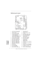 2
2 -
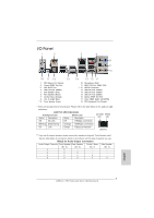 3
3 -
 4
4 -
 5
5 -
 6
6 -
 7
7 -
8
-
9
-
10
-
11
-
12
-
13
-
14
-
15
-
16
-
17
-
18
-
19
-
20
-
21
-
22
-
23
-
24
-
25
-
26
-
27
-
28
-
29
-
30
-
31
-
32
-
33
-
34
-
35
-
36
-
37
-
38
-
39
-
40
-
41
-
42
-
43
-
44
-
45
-
46
-
47
-
48
-
49
-
50
-
51
-
52
-
53
-
54
-
55
-
56
-
57
-
58
-
59
-
60
-
61
-
62
-
63
-
64
-
65
-
66
-
67
-
68
-
69
-
70
-
71
-
72
-
73
-
74
-
75
-
76
-
77
-
78
-
79
-
80
-
81
-
82
-
83
-
84
-
85
-
86
-
87
-
88
-
89
-
90
-
91
-
92
-
93
-
94
-
95
-
96
-
97
-
98
-
99
-
100
-
101
-
102
-
103
-
104
-
105
-
106
-
107
-
108
-
109
-
110
-
111
-
112
-
113
-
114
-
115
-
116
-
117
-
118
-
119
-
120
-
121
-
122
-
123
-
124
-
125
-
126
-
127
-
128
-
129
-
130
-
131
-
132
-
133
-
134
-
135
-
136
-
137
-
138
-
139
-
140
-
141
-
142
-
143
-
144
-
145
-
146
-
147
-
148
-
149
-
150
-
151
-
152
-
153
-
154
-
155
-
156
-
157
-
158
-
159
-
160
-
161
-
162
-
163
-
164
-
165
-
166
-
167
-
168
-
169
-
170
-
171
-
172
-
173
-
174
-
175
-
176
-
177
-
178
-
179
-
180
-
181
-
182
-
183
-
184
-
185
-
186
-
187
-
188
-
189
-
190
-
191
-
192
-
193
-
194
-
195
-
196
-
197
-
198
-
199
-
200
-
201
-
202
-
203
-
204
-
205
-
206
-
207
-
208
-
209
-
210
-
211
-
212
-
213
-
214
-
215
-
216
-
217
-
218
-
219
-
220
-
221
-
222
-
223
-
224
-
225
-
226
-
227
-
228
-
229
-
230
-
231
-
232
-
233
-
234
-
235
-
236
-
237
-
238
-
239
-
240
-
241
-
242
-
243
-
244
-
245
-
246
-
247
-
248
-
249
-
250
-
251
-
252
-
253
-
254
-
255
-
256
-
257
-
258
-
259
-
260
-
261
-
262
-
263
-
264
-
265
-
266
-
267
-
268
-
269
-
270
-
271
-
272
-
273
-
274
-
275
-
276
-
277
-
278
-
279
-
280
-
281
-
282
-
283
-
284
-
285
-
286
-
287
-
288
-
289
-
290
-
291
-
292
-
293
-
294
-
295
-
296
-
297
-
298
-
299
-
300
-
301
-
302
-
303
-
304
 |
 |
1
ASRock
P67 Extreme4 Gen3
Motherboard
English
Copyright Notice:
No part of this installation guide may be reproduced, transcribed, transmitted, or trans-
lated in any language, in any form or by any means, except duplication of documentation
by the purchaser for backup purpose, without written consent of ASRock Inc.
Products and corporate names appearing in this guide may or may not be registered
trademarks or copyrights of their respective companies, and are used only for identi
fi
ca-
tion or explanation and to the owners’ bene
fi
t, without intent to infringe.
Disclaimer:
Speci
fi
cations and information contained in this guide are furnished for informational use
only and subject to change without notice, and should not be constructed as a commit-
ment by ASRock. ASRock assumes no responsibility for any errors or omissions that may
appear in this guide.
With respect to the contents of this guide, ASRock does not provide warranty of any kind,
either expressed or implied, including but not limited to the implied warranties or condi-
tions of merchantability or
fi
tness for a particular purpose. In no event shall ASRock, its
directors, of
fi
cers, employees, or agents be liable for any indirect, special, incidental, or
consequential damages (including damages for loss of pro
fi
ts, loss of business, loss of
data, interruption of business and the like), even if ASRock has been advised of the pos-
sibility of such damages arising from any defect or error in the guide or product.
This device complies with Part 15 of the FCC Rules. Operation is subject to the following
two conditions:
(1) this device may not cause harmful interference, and
(2) this device must accept any interference received, including interference that
may cause undesired operation.
CALIFORNIA, USA ONLY
The Lithium battery adopted on this motherboard contains Perchlorate, a toxic substance
controlled in Perchlorate Best Management Practices (BMP) regulations passed by the
California Legislature. When you discard the Lithium battery in California, USA, please
follow the related regulations in advance.
“Perchlorate Material-special handling may apply, see
www.dtsc.ca.gov/hazardouswaste/perchlorate”
ASRock Website: http://www.asrock.com
Published June 2011
Copyright
©
2011 ASRock INC. All rights reserved.