ASRock X300M-STX User Manual
ASRock X300M-STX Manual
 |
View all ASRock X300M-STX manuals
Add to My Manuals
Save this manual to your list of manuals |
ASRock X300M-STX manual content summary:
- ASRock X300M-STX | User Manual - Page 1
- ASRock X300M-STX | User Manual - Page 2
interference received, including interference that may cause undesired operation. CALIFORNIA, USA ONLY The Lithium battery adopted on this motherboard contains Perchlorate, a toxic substance controlled in Perchlorate Best Management Practices (BMP) regulations passed by the California Legislature - ASRock X300M-STX | User Manual - Page 3
AUSTRALIA ONLY Our goods come with guarantees that cannot be excluded under the Australian Consumer Law. You are entitled to a replacement or refund for a major failure and compensation for any other reasonably foreseeable loss or damage caused by our goods. You are also entitled to have the goods - ASRock X300M-STX | User Manual - Page 4
1 Introduction 1 1.1 Package Contents 1 1.2 Specifications 2 1.3 Motherboard Layout 6 1.4 Front Panel 9 1.5 Rear Panel 10 Chapter Connectors 22 2.6 M.2 WiFi/BT Module Installation Guide 25 2.7 M.2_SSD (NGFF) Module Installation Guide 27 Chapter 3 Software and Utilities Operation - ASRock X300M-STX | User Manual - Page 5
4.4 Advanced Screen 35 4.4.1 CPU Configuration 36 4.4.2 North Bridge Configuration 37 4.4.3 South Bridge Configuration 38 4.4.4 Storage Configuration 39 4.4.5 ACPI Configuration 40 4.4.6 AMD CBS 41 4.4.7 AMD PBS 42 4.5 Tools 43 4.6 Hardware Health Event Monitoring Screen 45 4.7 - ASRock X300M-STX | User Manual - Page 6
the BIOS setup. Because the motherboard specifications and the BIOS software might be updated, the content of this documentation will be subject to change without notice. 1.1 Package Contents • X300M-STX Motherboard (Mini-STX Form Factor) • X300M-STX Quick Installation Guide • X300M-STX Support CD - ASRock X300M-STX | User Manual - Page 7
1.2 Specifications Platform • Mini-STX Form Factor • Solid Capacitor design CPU • Supports AMD AM4 Socket CPUs (Renoir, Picasso, Raven Ridge, up to 65W) • Supports CPU up to 65W • 5 Power Phase design Chipset • AMD X300 Memory • Dual Channel DDR4 Memory Technology • 2 x DDR4 SO-DIMM Slots • - ASRock X300M-STX | User Manual - Page 8
X300M-STX Audio LAN Front Panel I/O • Three graphics output options: D-Sub, DisplayPort 1.2 and HDMI • Supports Triple Monitor • Supports HDMI with max. resolution up to 4K x 2K (4096x2160) @ 60Hz • Supports D-Sub with max. resolution up to 1920x1200 @ 60Hz • Supports DisplayPort 1.2 with max. - ASRock X300M-STX | User Manual - Page 9
• 2 x CPU Fan Connectors (2 x 4-pin) • 1 x Front Panel Header • 1 x USB 2.0 Header (Supports 2 USB 2.0 ports) (Supports ESD Protection) • 1 x Audio Header • 1 x MONO Speaker Header BIOS Feature • AMI UEFI Legal BIOS with GUI support • Supports "Plug and Play" • ACPI 5.1 compliance wake up events - ASRock X300M-STX | User Manual - Page 10
X300M-STX Hardware Monitor • CPU involved with overclocking, including adjusting the setting in the BIOS, applying Untied Overclocking Technology, or using third-party damage caused by overclocking. Mini-STX Chassis Support List Vendor SilverStone Technology Inc. AKasa Model VT01S A-STX04-A1B - ASRock X300M-STX | User Manual - Page 11
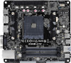
1.3 Motherboard Layout DC Jack 1 USB_4_5 CLRMOS1 1 2 Super 1 1 I/O SPEAKER1 1 CI1 3 M.2 PCIe SSD 4 M.2 WiFi DP1 HDMI1 VGA1 T: USB 2.0 USB2 B: USB 3.1 Gen1 USB3 Top: RJ-45 CPU_FAN2 CPU_FAN1 9 8 SOCKET AM4 RoHS DDR4_A1 BIOS ROM DDR4_B1 Mic In USB 3.1 Gen1 USB_TC_1 USB 3.1 - ASRock X300M-STX | User Manual - Page 12
Back Side View CMOS Battery X300M-STX M2_2 SATA3 10 CT1 SATA3 11 7 English - ASRock X300M-STX | User Manual - Page 13
No. Description 1 USB 2.0 Header (USB_4_5) 2 Clear CMOS Jumper (CLRCMOS1) 3 Chassis Intrusion Header (CI1) 4 MONO Speaker Header (SPEAKER1) 5 2 x 260-pin DDR4 SO-DIMM Slots (DDR4_A1, DDR4_B1) 6 Audio Header (AUDIO3) 7 System Panel Header (PANEL1) 8 CPU Fan Connector (CPU_FAN1) 9 CPU Fan Connector ( - ASRock X300M-STX | User Manual - Page 14
1.4 Front Panel X300M-STX 1 2 3 4 No. Description No. Description 1 Headphone/Headset Jack (AUDIO1) 3 USB 3.1 Gen1 Type-C Port (USB_TC_1) 2 USB 3.1 Gen1 Type-A Port (USB_1) 4 Microphone Input (AUDIO2) English 9 - ASRock X300M-STX | User Manual - Page 15
1.5 Rear Panel 7 1 2 3 4 5 6 No. Description 1 DC Jack* (Supports 19V DC Power Adapters) 2 Display Port 3 HDMI Port No. Description 4 D-Sub Port 5 USB 2.0 Port (USB_2) 6 USB 3.1 Gen1 Port (USB_3) 7 LAN RJ-45 Port** *Specification for - ASRock X300M-STX | User Manual - Page 16
X300M-STX Chapter 2 Installation This is a Mini-STX form factor motherboard. Before you install the motherboard, study the configuration of your chassis to ensure that the motherboard fits into it. Pre-installation Precautions Take note of the following precautions before you install motherboard - ASRock X300M-STX | User Manual - Page 17
2.1 Installing the CPU Unplug all power cables before installing the CPU. 1 2 12 English - ASRock X300M-STX | User Manual - Page 18
X300M-STX 3 13 English - ASRock X300M-STX | User Manual - Page 19
2.2 Installing the CPU Fan and Heatsink After you install the CPU into this motherboard, it is necessary to install a larger heatsink and cooling fan to dissipate heat. You also need to spray thermal grease between the CPU and the - ASRock X300M-STX | User Manual - Page 20
X300M-STX 3 4 4-pin FAN cable CPU_FAN1 15 English - ASRock X300M-STX | User Manual - Page 21
Installing the CPU Box Cooler -2 1 2 16 English - ASRock X300M-STX | User Manual - Page 22
X300M-STX 3 4 17 English - ASRock X300M-STX | User Manual - Page 23
5 4-pin FAN cable CPU_FAN1 18 English - ASRock X300M-STX | User Manual - Page 24
X300M-STX 2.3 Installing Memory Modules (SO-DIMM) This motherboard provides two 260-pin DDR4 (Double Data Rate 4) SO-DIMM slots. It is not allowed to install a DDR, DDR2 or DDR3 memory module into a DDR4 slot; otherwise, this motherboard and SO-DIMM may be damaged. DDR4 SO-DIMM Maximum Frequency - ASRock X300M-STX | User Manual - Page 25
The DIMM only fits in one correct orientation. It will cause permanent damage to the motherboard and the DIMM if you force the DIMM into the slot at incorrect orientation. 1 2 3 20 English - ASRock X300M-STX | User Manual - Page 26
X300M-STX 2.4 Jumpers Setup The illustration shows how jumpers are setup. When the jumper remove the jumper cap after clearing the CMOS. If you need to clear the CMOS when you just finish updating the BIOS, you must boot up the system first, and then shut it down before you do the clear-CMOS action - ASRock X300M-STX | User Manual - Page 27
jumper caps over these headers and connectors. Placing jumper caps over the headers and connectors will cause permanent damage to the motherboard. System Panel Header (9-pin PANEL1) (see p.6, No. 7) PLED+ PLEDPWRBTN# GND 1 GND RESET# GND HDLEDHDLED+ Connect the power button, reset button and - ASRock X300M-STX | User Manual - Page 28
X300M-STX MONO Speaker Header (4-pin SPEAKER1) (see p.6, No. 4) 1 Front_LFront_L+ Front_R+ Front_R 1) USB_PWR PP+ GND DUMMY 1 GND P+ PUSB_PWR There is one header on this motherboard. This USB 2.0 header can support two ports. CPU Fan Connectors (4-pin CPU_FAN1) (see p.6, No. 8) (4-pin CPU_FAN2) - ASRock X300M-STX | User Manual - Page 29
Chassis Intrusion Header (2-pin CI1) (see p.6, No. 3) 1 GND Signal This motherboard supports CASE OPEN detection feature that detects if the chassis cove has been removed. This feature requires a chassis with chassis intrusion detection design. Audio Header (5-pin - ASRock X300M-STX | User Manual - Page 30
X300M-STX 2.6 M.2 WiFi/BT Module Installation Guide The M.2, also known as the Next Generation Form Factor (NGFF), is a small size and versatile card edge connector that aims to replace mPCIe and mSATA. The M.2 Socket (Key E) supports type 2230 WiFi/BT module. Installing the WiFi/BT module Step 1 - ASRock X300M-STX | User Manual - Page 31
Step 4 Tighten the screw with a screwdriver to secure the module into place. Please do not overtighten the screw as this might damage the module. A 26 English - ASRock X300M-STX | User Manual - Page 32
X300M-STX 2.7 M.2_SSD (NGFF) Module Installation Guide The M.2, also known as the Next Generation Form Factor (NGFF), is a small size and versatile card edge connector that aims to replace mPCIe and mSATA. The Ultra M.2 Socket (M2_1) supports type 2280 M.2 PCI Express module up to Gen3 x4 (32 Gb/s). - ASRock X300M-STX | User Manual - Page 33
M.2_SSD (NGFF) Module Support List Vendor ADATA ADATA Apacer Intel Intel INTEL INTEL INTEL INTEL Kingston OCZ RD400-256G (NVMe) WD WDS512G1X0C-00ENX0 (NVMe) WD WDS256G1X0C-00ENX0 (NVMe) For the latest updates of M.2_SSD (NFGG) module support list, please visit our website for details. English 28 - ASRock X300M-STX | User Manual - Page 34
X300M-STX Chapter 3 Software and Utilities Operation 3.1 Installing Drivers The Support CD that comes with the motherboard contains necessary drivers and useful utilities that enhance the motherboard's features. Running The Support CD To begin using the support CD, insert the CD into your CD-ROM - ASRock X300M-STX | User Manual - Page 35
button on the system chassis. You may also restart by turning the system off and then back on. Because the UEFI software is constantly being updated, the following UEFI setup screens and descriptions are for reference purpose only, and they may not exactly match what you see on your screen - ASRock X300M-STX | User Manual - Page 36
X300M-STX 4.1.2 Navigation Keys Use < > key or < > key to choose among the selections on the menu bar, and use < > key or < > key to move the cursor up - ASRock X300M-STX | User Manual - Page 37
4.2 Main Screen When you enter the UEFI SETUP UTILITY, the Main screen will appear and display the system overview. 32 English - ASRock X300M-STX | User Manual - Page 38
you can set up overclocking features. X300M-STX Because the UEFI software is constantly being updated, the following UEFI setup screens and descriptions cycle is needed after selecting [Auto]. Warning: S3 is not supported on systems where SMT is disabled. DRAM Timing Configuration DRAM Information - ASRock X300M-STX | User Manual - Page 39
DRAM Frequency If [Auto] is selected, the motherboard will detect the memory module(s) inserted and assign the appropriate frequency automatically. Voltage Configuration DRAM Voltage Use this to select DRAM Voltage. The default value - ASRock X300M-STX | User Manual - Page 40
X300M-STX 4.4 Advanced Screen In this section, you may set the configurations for the Auto] is selected, the resolution will be set to 1920 x 1080 if the monitor supports Full HD resolution. If the monitor does not support Full HD resolution, then the resolution will be set to 1024 x 768. When [ - ASRock X300M-STX | User Manual - Page 41
4.4.1 CPU Configuration Cool 'n' Quiet Use this item to enable or disable AMD's Cool 'n' QuietTM technology. The default value is [Enabled]. Configuration options: [Enabled] and [Disabled]. If you install Windows® OS and want to enable this function, please set this item to [Enabled]. Please note - ASRock X300M-STX | User Manual - Page 42
4.4.2 North Bridge Configuration X300M-STX SR-IOV Support Enable/disable the SR-IOV (Single Root IO Virtualization Support) if the system has SR-IOV capable PCIe devices. English 37 - ASRock X300M-STX | User Manual - Page 43
4.4.3 South Bridge Configuration Onboard HD Audio Enable/disable onboard HD audio. Set to Auto to enable onboard HD audio and automatically disable it when a sound card is installed. Internal Speaker Select Internal Speaker. Deep Sleep Configure deep sleep mode for power saving when the computer is - ASRock X300M-STX | User Manual - Page 44
4.4.4 Storage Configuration X300M-STX SATA Controller(s) Enable/disable the SATA controllers. SATA Mode AHCI: Supports new features that improve performance. RAID: Combine multiple disk drives into a logical unit. 39 English - ASRock X300M-STX | User Manual - Page 45
4.4.5 ACPI Configuration Suspend to RAM It is recommended to select auto for ACPI S3 power saving. ACPI HPET Table Enable the High Precision Event Timer for better performance and to pass WHQL tests. Onboard LAN Power On Allow the system to be waked up by a onboard LAN. RTC Alarm Power On Allow the - ASRock X300M-STX | User Manual - Page 46
4.4.6 AMD CBS X300M-STX The AMD CBS menu accesses AMD specific features. English 41 - ASRock X300M-STX | User Manual - Page 47
4.4.7 AMD PBS The AMD PBS menu accesses AMD specific features. 42 English - ASRock X300M-STX | User Manual - Page 48
4.5 Tools X300M-STX Easy Driver Installer For users that don't have an optical disk drive to install the drivers from our support CD, Easy Driver Installer is a handy tool in the UEFI that installs the Save UEFI files in your USB storage device and run Instant Flash to update your UEFI. 43 English - ASRock X300M-STX | User Manual - Page 49
Internet Flash - DHCP (Auto IP), Auto Internet Flash downloads and updates the latest UEFI firmware version from our servers for you. Please setup network configuration before using Internet Flash. *For BIOS backup and recovery purpose, it is recommended to plug in your USB pen drive before using - ASRock X300M-STX | User Manual - Page 50
X300M-STX 4.6 Hardware Health Event Monitoring Screen This section allows you to monitor the status of the hardware on your system, including the parameters of the CPU temperature, motherboard temperature, fan speed and voltage. CPU Fan 1 Setting Select a fan mode for CPU Fan 1, or choose Customize - ASRock X300M-STX | User Manual - Page 51
are unable to change the settings in the UEFI Setup Utility. Leave it blank and press enter to remove the password. Secure Boot Enable to support Secure Boot. 46 English - ASRock X300M-STX | User Manual - Page 52
X300M-STX 4.8 Boot Screen This section displays the available devices on your system for you to configure the boot settings and the boot priority. Fast Boot Fast - ASRock X300M-STX | User Manual - Page 53
Above 4G Decoding Enable/disable the 64-bit capable devices to be decoded in above 4G address space. CSM (Compatibility Support Module) CSM Enable to launch the Compatibility Support Module. Please do not disable unless you're running a WHCK test. Launch PXE OpROM Policy Select UEFI only to run - ASRock X300M-STX | User Manual - Page 54
4.9 Exit Screen X300M-STX Save Changes and Exit When you select this option the following message, "Save configuration changes and exit setup?" will pop out. Select [OK] to save - ASRock X300M-STX | User Manual - Page 55
FCC Part 2 Section 2.1077(a) Responsible Party Name: ASRock Incorporation Address: 13848 Magnolia Ave, Chino, CA91710 Phone/Fax No: +1-909-590-8308/+1-909-590-1026 hereby declares that the product Product Name : Motherboard Model Number : X300M-STX Conforms to the following speci cations: FCC Part15 - ASRock X300M-STX | User Manual - Page 56
EU Declaration of Conformity For the following equipment: Motherboard (Product Name) X300M-STX (Model Designation / Trade Name) ڛEMC -Directive 2014/30/EU (from April 20th, 2016) ☐ EN 55022:2010/AC:2011 Class B ڛEN 55024:2010/A1:2015 ڛEN
-
 1
1 -
 2
2 -
 3
3 -
 4
4 -
 5
5 -
 6
6 -
 7
7 -
8
-
9
-
10
-
11
-
12
-
13
-
14
-
15
-
16
-
17
-
18
-
19
-
20
-
21
-
22
-
23
-
24
-
25
-
26
-
27
-
28
-
29
-
30
-
31
-
32
-
33
-
34
-
35
-
36
-
37
-
38
-
39
-
40
-
41
-
42
-
43
-
44
-
45
-
46
-
47
-
48
-
49
-
50
-
51
-
52
-
53
-
54
-
55
-
56
 |
 |