ASRock X470 Master SLI/ac User Manual
ASRock X470 Master SLI/ac Manual
 |
View all ASRock X470 Master SLI/ac manuals
Add to My Manuals
Save this manual to your list of manuals |
ASRock X470 Master SLI/ac manual content summary:
- ASRock X470 Master SLI/ac | User Manual - Page 1
- ASRock X470 Master SLI/ac | User Manual - Page 2
documentation are furnished for informational use only and subject to change without notice, and should not be constructed as a commitment by ASRock. ASRock assumes no responsibility for any errors or omissions that may appear in this documentation. With respect to the contents of this documentation - ASRock X470 Master SLI/ac | User Manual - Page 3
if the goods fail to be of acceptable quality and the failure does not amount to a major failure. If you require assistance please call ASRock Tel : +886-2-28965588 ext.123 (Standard International call charges apply) The terms HDMI™ and HDMI High-Definition Multimedia Interface, and the HDMI logo - ASRock X470 Master SLI/ac | User Manual - Page 4
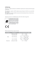
minimum distance 20cm between the radiator & your body. Operations in the 5.15-5.35GHz band are restricted to indoor usage only. Radio transmit power per transceiver type Function WiFi Bluetooth Frequency 2400-2483.5 MHz 5150-5250 MHz 5250-5350 MHz 5470-5725 MHz 2400-2483.5 MHz Maximum Output - ASRock X470 Master SLI/ac | User Manual - Page 5
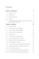
-802.11ac Module and ASRock WiFi 2.4/5 GHz Antennas (for X470 Master SLI/ac only) 12 Chapter 2 Installation 14 2.1 Installing the CPU 15 2.2 Installing the CPU Fan and Heatsink 17 2.3 Installing Memory Modules (DIMM) 26 2.4 Expansion Slots (PCI Express Slots) 29 2.5 Jumpers Setup 30 - ASRock X470 Master SLI/ac | User Manual - Page 6
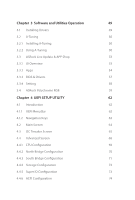
49 3.2 A-Tuning 50 3.2.1 Installing A-Tuning 50 3.2.2 Using A-Tuning 50 3.3 ASRock Live Update & APP Shop 53 3.3.1 UI Overview 53 3.3.2 Apps 54 3.3.3 BIOS & Drivers 57 3.3.4 Setting 58 3.4 ASRock Polychrome RGB 59 Chapter 4 UEFI SETUP UTILITY 62 4.1 Introduction 62 4.1.1 UEFI - ASRock X470 Master SLI/ac | User Manual - Page 7
4.4.7 Trusted Computing 75 4.4.8 AMD CBS 76 4.4.9 AMD PBS 84 4.5 Tools 85 4.6 Hardware Health Event Monitoring Screen 87 4.7 Security Screen 90 4.8 Boot Screen 91 4.9 Exit Screen 93 - ASRock X470 Master SLI/ac | User Manual - Page 8
list on ASRock's website as well. ASRock website http://www.asrock.com. 1.1 Package Contents • ASRock X470 Master SLI/ac / X470 Master SLI Motherboard (ATX Form Factor) • ASRock X470 Master SLI/ac / X470 Master SLI Quick Installation Guide • ASRock X470 Master SLI/ac / X470 Master SLI Support CD - ASRock X470 Master SLI/ac | User Manual - Page 9
• Digi Power design (Intersil) • 12 Power Phase design • Supports 105W Water Cooling (Pinnacle Ridge); Supports 95W Water Cooling (Summit Ridge); Supports 65W Water Cooling (Raven Ridge) Chipset • AMD Promontory X470 Memory • Dual Channel DDR4 Memory Technology • 4 x DDR4 DIMM Slots • AMD Ryzen - ASRock X470 Master SLI/ac | User Manual - Page 10
X470 Master SLI/ac / X470 Master SLI • Supports AMD Quad CrossFireXTM and CrossFireXTM • Supports NVIDIA® Quad SLITM and SLITM • 15μ Gold Contact in VGA PCIe Slot (PCIE1) Graphics • Integrated AMD RadeonTM Vega Series Graphics in Ryzen Series APU* * Actual support may vary by CPU • DirectX 12, - ASRock X470 Master SLI/ac | User Manual - Page 11
NVMe SSD as boot disks * Supports ASRock U.2 Kit Connector • 1 x COM Port Header • 1 x TPM Header • 1 x Power LED and Speaker Header • 1 x AMD Fan LED Header * The AMD Fan LED Header supports LED strips of maximum load of 3A (36W) and length up to 2.5M. • 1 x RGB LED Header * Supports in total - ASRock X470 Master SLI/ac | User Manual - Page 12
X470 Master SLI/ac / X470 Master SLI * The CPU/Water Pump Fan supports the water cooler fan of maximum 2A (24W) fan power. • 3 x Chassis/Water Pump Fan Connectors (4-pin) (Smart Fan Speed Control) * The Chassis/Water Pump Fan supports the water cooler fan of maximum 2A (24W) fan power. * CPU_FAN2/ - ASRock X470 Master SLI/ac | User Manual - Page 13
ready (ErP/EuP ready power supply is required) * For detailed product information, please visit our website: http://www.asrock.com Please realize that there is a certain risk involved with overclocking, including adjusting the setting in the BIOS, applying Untied Overclocking Technology, or using - ASRock X470 Master SLI/ac | User Manual - Page 14
Motherboard Layout X470 Master SLI/ac / X470 Master SLI M2_WIFI_1* ATX12V1 ATX12V2 CPU_FAN2/WP CPU_FAN1 PS2 Keyboard/ Mouse HDMI1 ATXPWR1 DDR4_B2 (64 bit, 288-pin module) DDR4_B1 (64 bit, 288-pin module) DDR4_A2 (64 bit, 288-pin module) DDR4_A1 (64 bit, 288-pin module) SOCKET AM4 USB - ASRock X470 Master SLI/ac | User Manual - Page 15
USB Header (USB_5) 11 AMD Fan LED Header (AMD_FAN_LED1) 12 Chassis/Water Pump Fan Connector (CHA_FAN1/WP) 13 SATA3 Connectors (SATA3_5_6) 14 SATA3 Connectors (SATA3_3_4) 15 SATA3 Connectors (SATA3_1_2) 16 System Panel Header (PANEL1) 17 RGB LED Header (RGB_LED1) 18 Clear CMOS Jumper (CLRCMOS1) 19 - ASRock X470 Master SLI/ac | User Manual - Page 16
1.4 I/O Panel X470 Master SLI/ac 1 X470 Master SLI/ac / X470 Master SLI 35 2 46 15 14 13 No. Description 1 PS/2 Mouse/Keyboard Port 2 LAN RJ-45 Port* 3 Central / Bass (Orange) 4 Rear Speaker (Black) 5 Line In (Light Blue) 6 - ASRock X470 Master SLI/ac | User Manual - Page 17
X470 Master SLI 1 35 2 46 14 13 12 10 11 9 87 No. Description 1 PS/2 Mouse/Keyboard Port 2 LAN RJ-45 Port* 3 Central / Bass (Orange) 4 Rear Speaker (Black) 5 Line - ASRock X470 Master SLI/ac | User Manual - Page 18
X470 Master SLI/ac / X470 Master SLI * There are two LEDs on each LAN port. Please refer to the table below for the LAN port LED indications. ACT/LINK LED SPEED LED - ASRock X470 Master SLI/ac | User Manual - Page 19
and ASRock WiFi 2.4/5 GHz Antennas (for X470 Master SLI/ac only) WiFi-802.11ac + BT Module This motherboard comes with an exclusive WiFi 802.11 a/b/g/n/ac + BT v4.2 module (pre-installed on the rear I/O panel) that offers support for WiFi 802.11 a/b/ g/n/ac connectivity standards and Bluetooth v4 - ASRock X470 Master SLI/ac | User Manual - Page 20
X470 Master SLI/ac / X470 Master SLI WiFi Antennas Installation Guide Step 1 Prepare the WiFi 2.4/5 GHz Antennas that come with the package. Step 2 Connect the two WiFi 2.4/5 GHz Antennas to the antenna connectors. Turn the antenna - ASRock X470 Master SLI/ac | User Manual - Page 21
Take note of the following precautions before you install motherboard components or change any motherboard settings. • Make sure to unplug the power cord before installing or removing the motherboard. Failure to do so may cause physical injuries to you and damages to motherboard components - ASRock X470 Master SLI/ac | User Manual - Page 22
2.1 Installing the CPU X470 Master SLI/ac / X470 Master SLI Unplug all power cables before installing the CPU. 1 2 English 15 - ASRock X470 Master SLI/ac | User Manual - Page 23
3 16 English - ASRock X470 Master SLI/ac | User Manual - Page 24
X470 Master SLI/ac / X470 Master SLI 2.2 Installing the CPU Fan and Heatsink After you install the CPU into this fastened and in good contact with each other. Please turn off the power or remove the power cord before changing a CPU or heatsink. Installing the CPU Box Cooler SR1 1 2 17 English - ASRock X470 Master SLI/ac | User Manual - Page 25
3 4 18 CPU_FAN1 English - ASRock X470 Master SLI/ac | User Manual - Page 26
X470 Master SLI/ac / X470 Master SLI Installing the AM4 Box Cooler SR2 1 2 19 English - ASRock X470 Master SLI/ac | User Manual - Page 27
3 20 English - ASRock X470 Master SLI/ac | User Manual - Page 28
X470 Master SLI/ac / X470 Master SLI 4 CPU_FAN1 5 RGB LED Cable 4-pin FAN cable CPU_FAN1 +12V AMD_FAN_LED1 *The diagram shown here are for reference only. Please refer to page 35 for the orientation of AMD Fan LED Header (AMD_FAN_LED1). 21 English - ASRock X470 Master SLI/ac | User Manual - Page 29
Installing the AM4 Box Cooler SR3 1 2 22 English - ASRock X470 Master SLI/ac | User Manual - Page 30
X470 Master SLI/ac / X470 Master SLI 3 4 23 English - ASRock X470 Master SLI/ac | User Manual - Page 31
5 CPU_FAN1 24 English - ASRock X470 Master SLI/ac | User Manual - Page 32
SLI/ac / X470 Master SLI 6 CPU_FAN1 +12V AMD_FAN_LED1 or 7 CPU_FAN1 AMD_FAN_LED1 USB_5 Please note that only one cable should be used at a time in this step. If you select AMD_FAN_LED1, please install ASRock utility "ASRock Polychrome RGB". If you select USB connector, please install AMD - ASRock X470 Master SLI/ac | User Manual - Page 33
3. It is not allowed to install a DDR, DDR2 or DDR3 memory module into a DDR4 slot; otherwise, this motherboard and DIMM may be damaged. DDR4 UDIMM Maximum Frequency Support Ryzen Series CPUs (Pinnacle Ridge): UDIMM Memory Slot A1 A2 B1 B2 - SR - - - DR - - - SR - SR - DR - DR - ASRock X470 Master SLI/ac | User Manual - Page 34
X470 Master SLI/ac / X470 Master SLI Ryzen Series CPUs (Summit Ridge): UDIMM Memory Slot A1 A2 B1 B2 - SR - - - DR - - - SR - SR - DR - DR SR SR SR SR SR/DR DR SR/DR DR Frequency (Mhz) 2667 2667 2667 - ASRock X470 Master SLI/ac | User Manual - Page 35
The DIMM only fits in one correct orientation. It will cause permanent damage to the motherboard and the DIMM if you force the DIMM into the slot at incorrect orientation. 1 2 3 28 English - ASRock X470 Master SLI/ac | User Manual - Page 36
X470 Master SLI/ac / X470 Master SLI 2.4 Expansion Slots (PCI Express Slots) There are 6 PCI Express slots on the motherboard. Before installing an expansion card, please make sure that the power supply is switched off or the power cord is unplugged. Please read the documentation of the expansion - ASRock X470 Master SLI/ac | User Manual - Page 37
unplug the power cord from the power supply. After waiting for 15 seconds, use a jumper cap to short the pins on CLRCMOS1 for 5 seconds. However, please do not clear the CMOS right after you update the BIOS. If you need to clear the CMOS when you just finish updating the BIOS, you must boot up the - ASRock X470 Master SLI/ac | User Manual - Page 38
X470 Master SLI/ac / X470 Master SLI 2.6 Onboard Headers and Connectors Onboard headers and connectors are NOT jumpers in S1/S3 sleep state. The LED is off when the system is in S4 sleep state or powered off (S5). HDLED (Hard Drive Activity LED): Connect to the hard drive activity LED on the chassis - ASRock X470 Master SLI/ac | User Manual - Page 39
PLED- Please connect the chassis power LED and the chassis speaker to this header. These six SATA3 connectors support SATA data cables for internal the AMD SR3 Heatsink. USB_PWR PP+ GND DUMMY 1 GND P+ PUSB_PWR There are two headers on this motherboard. Each USB 2.0 header can support two ports - ASRock X470 Master SLI/ac | User Manual - Page 40
X470 Master SLI/ac / X470 Master SLI Front Panel Audio Header (9-pin HD_AUDIO1) (see p.7, No. 27) GND PRESENCE# MIC_RET OUT_RET 1 OUT2_L J_SENSE OUT2_R MIC2_R MIC2_L This header is for connecting audio devices to the front audio panel. 1. High Definition Audio supports Jack Sensing, but the - ASRock X470 Master SLI/ac | User Manual - Page 41
Connector (24-pin ATXPWR1) (see p.7, No. 7) 12 24 1 13 This motherboard provides a 24-pin ATX power connector. To use a 20-pin ATX power supply, please plug it along Pin 1 and Pin 13. ATX 12V Power Connector (8-pin ATX12V1) (see p.7, No. 1) 8 5 This motherboard pro- vides an 8-pin ATX 12V - ASRock X470 Master SLI/ac | User Manual - Page 42
X470 Master SLI/ac / X470 Master SLI TPM Header (17-pin TPMS1) (see p.7, No. 25) 1 AMD FAN LED Header (4-pin AMD_FAN_ LED1) (see p.7, No. 11) 1 12V G R B RGB LED Header (4-pin RGB_LED1) (see p.7, No. 17) 1 12V G R B PCICLK FRAME PCIRST# LAD3 +3V LAD0 +3VSB GND GND SMB_CLK_MAIN SMB_DATA_MAIN - ASRock X470 Master SLI/ac | User Manual - Page 43
effects. Caution: Never install the Addressable LED cable in the wrong orientation; otherwise, the cable may be damaged. *Please refer to page 61 for further instructions on this header. English 36 - ASRock X470 Master SLI/ac | User Manual - Page 44
X470 Master SLI/ac / X470 Master SLI 2.7 SLITM and Quad SLITM Operation Guide This motherboard supports NVIDIA® driver supports NVIDIA® SLITM technology. Download the drivers from the NVIDIA® website: www.nvidia.com 3. Make sure that your power supply unit (PSU) can provide at least the minimum power - ASRock X470 Master SLI/ac | User Manual - Page 45
SLI_HB_ Bridge_2S Card to the goldfingers on each graphics card. Make sure the ASRock SLI_ HB_Bridge_2S Card is firmly in place. SLI_HB_Bridge_2S Card ASRock SLI_HB_Bridge_2S Card Step 4 Connect a VGA cable or a DVI cable to the monitor connector or the DVI connector of the graphics card that is - ASRock X470 Master SLI/ac | User Manual - Page 46
X470 Master SLI/ac / X470 Master SLI 2.7.2 Driver Installation and Setup Install the graphics card drivers to your system. After icon in the Windows® system tray. Step 2 In the left pane, click Set SLI and PhysX configuration. Then select Maximize 3D performance and click Apply. Step 3 Reboot your - ASRock X470 Master SLI/ac | User Manual - Page 47
only use identical CrossFireXTM-ready graphics cards that are AMD certified. 2. Make sure that your graphics card driver supports AMD CrossFireXTM technology. Download the drivers from the AMD's website: www.amd.com 3. Make sure that your power supply unit (PSU) can provide at least the minimum - ASRock X470 Master SLI/ac | User Manual - Page 48
X470 Master SLI/ac / X470 Master SLI Step 3 Connect a VGA cable or a DVI cable to the monitor connector or the DVI connector of the graphics card that is inserted to PCIE1 slot. 41 English - ASRock X470 Master SLI/ac | User Manual - Page 49
Driver Installation and Setup Step 1 Power on your computer and boot into OS. Step 2 Remove the AMD drivers if you have any VGA drivers installed in your system. The Catalyst Uninstaller is an optional download. We recommend using this utility to uninstall any previously installed Catalyst drivers - ASRock X470 Master SLI/ac | User Manual - Page 50
X470 Master SLI/ac / X470 Master SLI 2.9 M.2_SSD (NGFF) Module Installation Guide (M2_1) The M.2, also known as the Next Generation Form Factor (NGFF), is a small size and versatile card edge connector that aims to replace mPCIe and mSATA. The Ultra M.2 Socket (M2_1) supports M Key type 2230/2242/ - ASRock X470 Master SLI/ac | User Manual - Page 51
, please loosen the screws to remove the M.2 heatsink. E D C B A E D C B A 20o E D NUT2 NUT1 Step 4 Gently insert the M.2 (NGFF) SSD module into the M.2 slot. Please be aware that the M.2 (NGFF) SSD module only fits in one orientation. *If you insert Type 22110 M.2 SSD, please make - ASRock X470 Master SLI/ac | User Manual - Page 52
X470 Master SLI/ac / X470 Master SLI M.2_SSD (NGFF) Module Support nvme) SSDPEKKF512G7 NVME Kingston SHPM2280P2 / 240G (Gen2 x4) SKC1000/480G SKC1000/960GB NVME PX-512M8PeG SM951 (NVME) updates of M.2_SSD (NFGG) module support list, please visit our website for details: http://www.asrock.com English - ASRock X470 Master SLI/ac | User Manual - Page 53
2.10 M.2_SSD (NGFF) Module Installation Guide (M2_2) The M.2, also known as the Next Generation Form Factor (NGFF), is a small size and versatile card edge connector that aims to replace mPCIe and mSATA. The M.2 Socket (M2_2) supports M Key type 2230/2242/2260/2280 M.2 SATA3 6.0 Gb/s module and M.2 - ASRock X470 Master SLI/ac | User Manual - Page 54
D C B A E D C B A X470 Master SLI/ac / X470 Master SLI Step 3 Move the standoff based on the module type location on the motherboard. Step 5 Gently insert the M.2 (NGFF) SSD module into the M.2 slot. Please be aware that the M.2 (NGFF) SSD module only fits in one orientation. English E - ASRock X470 Master SLI/ac | User Manual - Page 55
SATA SATA SATA SATA SATA SATA P/N INTEL 6000P-SSDPEKKF256G7 (nvme) INTEL 6000P-SSDPEKKF512G7 (nvme) Kingston SHPM2280P2 / 240G (Gen2 x4) Samsung XP941-MZHPU512HCGL( the latest updates of M.2_SSD (NFGG) module support list, please visit our website for details: http://www.asrock.com English - ASRock X470 Master SLI/ac | User Manual - Page 56
X470 Master SLI/ac / X470 Master SLI Chapter 3 Software and Utilities Operation 3.1 Installing Drivers The Support CD that comes with the motherboard contains necessary drivers and useful utilities that enhance the motherboard's features. Running The Support CD To begin using the support CD, insert - ASRock X470 Master SLI/ac | User Manual - Page 57
multi purpose software suite with a new interface, more new features and improved utilities. 3.2.1 Installing A-Tuning A-Tuning can be downloaded from ASRock Live Update & APP Shop. After the installation, you will find the icon "A-Tuning" on your desktop. Double-click the "ATuning" icon, A-Tuning - ASRock X470 Master SLI/ac | User Manual - Page 58
X470 Master SLI/ac / X470 Master SLI OC Tweaker Configurations for overclocking the system. System Info View information about the system. *The System Browser tab may not appear for certain models. 51 English - ASRock X470 Master SLI/ac | User Manual - Page 59
different fan speeds using the graph. The fans will automatically shift to the next speed level when the assigned temperature is met. Settings Configure ASRock A-Tuning. Click to select "Auto run at Windows Startup" if you want A-Tuning to be launched when you start up the Windows operating system - ASRock X470 Master SLI/ac | User Manual - Page 60
X470 Master SLI/ac / X470 Master SLI 3.3 ASRock Live Update & APP Shop The ASRock Live Update & APP Shop is an online store for purchasing and downloading software applications for your ASRock computer. You can quickly and easily install various apps and support utilities. With ASRock Live Update & - ASRock X470 Master SLI/ac | User Manual - Page 61
3.3.2 Apps When the "Apps" tab is selected, you will see all the available apps on screen for you to download. Installing an App Step 1 Find the app you want to install. The most recommended app appears on the left side of the screen. The other various apps are shown on the right. Please scroll up - ASRock X470 Master SLI/ac | User Manual - Page 62
X470 Master SLI/ac / X470 Master SLI Step 3 If you want to install the app, click on the red icon to start downloading. Step 4 When installation completes, you can find the green " - ASRock X470 Master SLI/ac | User Manual - Page 63
Upgrading an App You can only upgrade the apps you have already installed. When there is an available new version for your app, you will find the mark of "New Version" appears below the installed app icon. Step 1 Click on the app icon to see more details. Step 2 Click on the yellow icon to start - ASRock X470 Master SLI/ac | User Manual - Page 64
X470 Master SLI/ac / X470 Master SLI 3.3.3 BIOS & Drivers Installing BIOS or Drivers When the "BIOS & Drivers" tab is selected, you will see a list of recommended or critical updates for the BIOS or drivers. Please update them all soon. Step 1 Please check the item information before update. Click - ASRock X470 Master SLI/ac | User Manual - Page 65
3.3.4 Setting In the "Setting" page, you can change the language, select the server location, and determine if you want to automatically run the ASRock Live Update & APP Shop on Windows startup. 58 English - ASRock X470 Master SLI/ac | User Manual - Page 66
X470 Master SLI/ac / X470 Master SLI 3.4 ASRock Polychrome RGB ASRock Polychrome RGB is a lighting control utility specifically designed for unique individuals with sophisticated tastes to build their own stylish colorful lighting system. Simply by connecting the LED - ASRock X470 Master SLI/ac | User Manual - Page 67
and unplug the power cord from the power supply. Failure to do so may cause damages to motherboard components. 1. Please note that the RGB LED strips do not come with the package. 2. The RGB LED header supports WS2812B addressable RGB LED strip (5V/Data/ GND), with a maximum power rating of 3A - ASRock X470 Master SLI/ac | User Manual - Page 68
X470 Master SLI/ac / X470 Master SLI ASRock Polychrome RGB Utility Now you can adjust the RGB LED color through the ASRock Polychrome RGB utility. Download this utility from the ASRock Live Update & APP Shop and start coloring your PC style your way! Drag the tab to customize your preference. - ASRock X470 Master SLI/ac | User Manual - Page 69
you power on the computer, otherwise, the Power-On-Self-Test (POST) will continue overclocking configurations Advanced For advanced system configurations Tool Useful tools H/W Monitor Displays current hardware status Security For security settings Boot For configuring boot settings and boot - ASRock X470 Master SLI/ac | User Manual - Page 70
X470 Master SLI/ac / X470 Master SLI 4.1.2 Navigation Keys Use < > key or < > key to choose among the selections on the menu bar, and use < > key or < > key to move the cursor up - ASRock X470 Master SLI/ac | User Manual - Page 71
4.2 Main Screen When you enter the UEFI SETUP UTILITY, the Main screen will appear and display the system overview. X470 Master SLI/ac X470 Master SLI 64 English - ASRock X470 Master SLI/ac | User Manual - Page 72
X470 Master SLI/ac / X470 Master SLI 4.3 OC Tweaker Screen In the OC Tweaker screen, you can set up overclocking features. Because the UEFI software is constantly being updated OC Mode. Overclock Mode Select the overclock mode. CPU Frequency and Voltage Change If this item is set to [Manual], the - ASRock X470 Master SLI/ac | User Manual - Page 73
power cycle is needed after selecting [Auto]. Warning: S3 is not supported on systems where SMT is disabled. DRAM Timing Configuration DRAM Frequency If [Auto] is selected, the motherboard will detect the memory module(s) inserted and assign the appropriate frequency automatically. AM4 Advance Boot - ASRock X470 Master SLI/ac | User Manual - Page 74
X470 Master SLI/ac / X470 Master SLI Load User Default Load previously saved user defaults. Save User UEFI Setup Profile to Disk It helps you to save current UEFI settings as an - ASRock X470 Master SLI/ac | User Manual - Page 75
and AMD PBS. Setting wrong values in this section may cause the system to malfunction. UEFI Configuration Active Page on Entry Select the default page when entering the UEFI setup utility. Full HD UEFI When [Auto] is selected, the resolution will be set to 1920 x 1080 if the monitor supports Full - ASRock X470 Master SLI/ac | User Manual - Page 76
4.4.1 CPU Configuration X470 Master SLI/ac / X470 Master SLI Cool 'n' Quiet Use this item to enable or disable AMD's Cool 'n' QuietTM technology. some memory modules or power supplies. Please set this item to [Disable] if above issue occurs. AMD fTPM Switch Use this to enable or disable AMD CPU - ASRock X470 Master SLI/ac | User Manual - Page 77
4.4.2 North Bridge Configuration SR-IOV Support Enable/disable the SR-IOV (Single Root IO Virtualization Support) if the system has SR-IOV capable PCIe devices. 70 English - ASRock X470 Master SLI/ac | User Manual - Page 78
/ac / X470 Master SLI 4.4.3 South Bridge Configuration Onboard HD Audio Enable/disable onboard HD audio. Set to Auto to enable onboard HD audio and automatically disable it when a sound card is installed. Front Panel Enable/disable front panel HD audio. Deep Sleep Configure deep sleep mode for power - ASRock X470 Master SLI/ac | User Manual - Page 79
4.4.4 Storage Configuration SATA Controller(s) Enable/disable the SATA controllers. SATA Mode AHCI: Supports new features that improve performance. RAID: Combine multiple disk drives into a logical unit. SATA Hot Plug Enable/disable the SATA Hot Plug function. 72 English - ASRock X470 Master SLI/ac | User Manual - Page 80
X470 Master SLI/ac / X470 Master SLI 4.4.5 Super IO Configuration Serial Port Enable or disable the Serial port. Serial Port Address Select the address of the Serial port. PS2 Y-Cable Enable the PS2 Y-Cable or set this option to Auto. 73 English - ASRock X470 Master SLI/ac | User Manual - Page 81
ACPI Configuration Suspend to RAM It is recommended to select auto for ACPI S3 power saving. ACPI HPET Table Enable the High Precision Event Timer for better performance and to pass WHQL tests. PS/2 Keyboard Power On Allow the system to be waked up by a PS/2 Keyboard. PCIE Devices Power On Allow the - ASRock X470 Master SLI/ac | User Manual - Page 82
4.4.7 Trusted Computing X470 Master SLI/ac / X470 Master SLI Security Device Support Enable or disable BIOS support for security device. English 75 - ASRock X470 Master SLI/ac | User Manual - Page 83
4.4.8 AMD CBS Zen Common Options RedirectForReturnDis From a workaround for GCC/C000005 issue for XV Core on CZ A0, setting MSRC001_1029 Decode Configuration (DE_CFG) bit 14 [DecfgNoRdrctForReturns] - ASRock X470 Master SLI/ac | User Manual - Page 84
X470 Master SLI/ac / X470 Master SLI Opcache Control Enables or disables the Opcache. OC Mode OC1 - 16 cores/3. symmetric multithreading. To re-enable SMT, a POWER CYCLE is needed after selecting the 'Auto' option. Warning: S3 is NOT SUPPORTED on systems where SMT is disabled. Streaming Stores - ASRock X470 Master SLI/ac | User Manual - Page 85
on memory populations and it will be ignored if the memory doesn't support the selected option. Memory interleaving size Controls the memory interleaving 256 or 512 bytes. Memory Clear When this feature is disabled, BIOS does not implement MemClear after memory training (only if non- - ASRock X470 Master SLI/ac | User Manual - Page 86
X470 Master SLI/ac / X470 Master SLI UMC Common Options DDR4 Common Options DRAM Controller Configuration DRAM Controller Configuration DRAM Power bus signals to Auto or Manual CAD Bus Drive Strength User Controls Drive Strength on CAD bus signals to Auto or Manual Data Bus Configuration Data Bus - ASRock X470 Master SLI/ac | User Manual - Page 87
BankGroupSwapAlt. Address Hash Bank Configure the bank address hashing. Address Hash CS Configure the CS address hashing. NVDIMM Memory MBIST MBIST Enable Configure the Memory MBIST. MBIST SubType Test Select MBIST Subtest - Single Chipselect, Multi Chipselect, Address Line Test or execute All test - ASRock X470 Master SLI/ac | User Manual - Page 88
X470 Master SLI/ac / X470 Master SLI Determinism Slider [Auto] Use default performance determinism settings cTDP Control [Auto] Use the fused cTDP. [Manual] User can set customized cTDP. Fan Control [Auto] Use the default fan controller settings. [Manual] User can set customized fan controller - ASRock X470 Master SLI/ac | User Manual - Page 89
Disable or enable OnChip SATA controller Sata RAS Support Disable or enable Sata RAS Support Sata Disabled AHCI Prefetch Function Configure the Sata ) Options SD Configuration Mode Select SD Mode. Ac Power Loss Options Select Ac Loss Control Method. I2C Configuration Options Uart Configuration - ASRock X470 Master SLI/ac | User Manual - Page 90
X470 Master SLI/ac / X470 Master SLI Chipselect Interleaving Interleave memory blocks across the DRAM chip selects for node 0. BankGroupSwap Configure the BankGroupSwap. BankGroupSwapAlt Configure the BankGroupSwapAlt. Address Hash Bank Configure the bank address hashing. Address - ASRock X470 Master SLI/ac | User Manual - Page 91
4.4.9 AMD PBS The AMD PBS menu accesses AMD specific features. 84 English - ASRock X470 Master SLI/ac | User Manual - Page 92
4.5 Tools X470 Master SLI/ac / X470 Master SLI RGB LED ASRock RGB LED allows you to adjust the RGB LED color to your liking. Easy RAID Installer Easy RAID Installer helps you to copy the RAID driver from the support CD to your USB storage device. After copying the drivers please change the SATA - ASRock X470 Master SLI/ac | User Manual - Page 93
Instant Flash Save UEFI files in your USB storage device and run Instant Flash to update your UEFI. Network Configuration Use this to configure internet connection settings for Internet Flash. Internet Setting Enable or disable sound effects in the setup utility. - ASRock X470 Master SLI/ac | User Manual - Page 94
X470 Master SLI/ac / X470 Master SLI 4.6 Hardware Health Event Monitoring Screen This section allows you to monitor the status of the hardware on your system, including the parameters of the CPU - ASRock X470 Master SLI/ac | User Manual - Page 95
CPU Optional Fan Control Mode Select PWM mode or DC mode for CPU Optional fan. CPU Optional Fan Setting Select a fan mode for CPU Optional fan, or choose Customize to set 5 CPU temperatures and assign a respective fan speed for each temperature. CPU Optional Fan Temp Source Select a fan temperature - ASRock X470 Master SLI/ac | User Manual - Page 96
X470 Master SLI/ac / X470 Master SLI Chassis Fan 3 Control Mode Select PWM mode or DC mode for Chassis Fan 3. Chassis Fan 3 Setting Select a fan mode for Chassis Fan 3, or choose Customize - ASRock X470 Master SLI/ac | User Manual - Page 97
you may set or change the supervisor/user password for the system. You may also clear the user password. Supervisor Password Set or change the password for the administrator account. Only Leave it blank and press enter to remove the password. Secure Boot Enable to support Secure Boot. 90 English - ASRock X470 Master SLI/ac | User Manual - Page 98
X470 Master SLI/ac / X470 Master SLI 4.8 Boot Screen This section displays the available devices on your system for you to configure the boot settings and the boot priority. Fast Boot Fast Boot minimizes your computer's boot time. In fast mode you may not boot from an USB storage device. Boot From - ASRock X470 Master SLI/ac | User Manual - Page 99
AddOn ROM messages or configure the AddOn ROM if you've enabled Full Screen Logo. Disable for faster boot speed. CSM (Compatibility Support Module) CSM Enable to launch the Compatibility Support Module. Please do not disable unless you're running a WHCK test. Launch PXE OpROM Policy Select UEFI only - ASRock X470 Master SLI/ac | User Manual - Page 100
4.9 Exit Screen X470 Master SLI/ac / X470 Master SLI Save Changes and Exit When you select this option the following message, "Save configuration changes and exit setup?" will pop out. Select [OK] to save - ASRock X470 Master SLI/ac | User Manual - Page 101
dealer for further information. For technical questions, please submit a support request form at https://event.asrock.com/tsd.asp ASRock Incorporation 2F., No.37, Sec. 2, Jhongyang S. Rd., Beitou District, Taipei City 112, Taiwan (R.O.C.) ASRock EUROPE B.V. Bijsterhuizen 11-11 6546 AR Nijmegen The - ASRock X470 Master SLI/ac | User Manual - Page 102
2 Section 2.1077(a) Responsible Party Name: ASRock Incorporation Address: 13848 Magnolia Ave, Chino, CA91710 Phone/Fax No: +1-909-590-8308/+1-909-590-1026 hereby declares that the product Product Name : Motherboard Model Number : X470 Master SLI/ac / X470 Master SLI Conforms to the following speci - ASRock X470 Master SLI/ac | User Manual - Page 103
EU Declaration of Conformity For the following equipment: Motherboard (Product Name) X470 Master SLI/ac / X470 Master SLI / ASRock (Model Designation / Trade Name) ASRock Incorporation (Manufacturer Name) 2F., No.37, Sec. 2, Jhongyang S. Rd., Beitou District, Taipei City 112, Taiwan (R.O.C.) (
-
 1
1 -
 2
2 -
 3
3 -
 4
4 -
 5
5 -
 6
6 -
 7
7 -
8
-
9
-
10
-
11
-
12
-
13
-
14
-
15
-
16
-
17
-
18
-
19
-
20
-
21
-
22
-
23
-
24
-
25
-
26
-
27
-
28
-
29
-
30
-
31
-
32
-
33
-
34
-
35
-
36
-
37
-
38
-
39
-
40
-
41
-
42
-
43
-
44
-
45
-
46
-
47
-
48
-
49
-
50
-
51
-
52
-
53
-
54
-
55
-
56
-
57
-
58
-
59
-
60
-
61
-
62
-
63
-
64
-
65
-
66
-
67
-
68
-
69
-
70
-
71
-
72
-
73
-
74
-
75
-
76
-
77
-
78
-
79
-
80
-
81
-
82
-
83
-
84
-
85
-
86
-
87
-
88
-
89
-
90
-
91
-
92
-
93
-
94
-
95
-
96
-
97
-
98
-
99
-
100
-
101
-
102
-
103
 |
 |